VEVOR TW180 User manual

INSTALLATION AND OPERATING INSTRUCTIONS ANCHOR WINCHES
Drum Winch
1000W
TW240
TW200
TW180

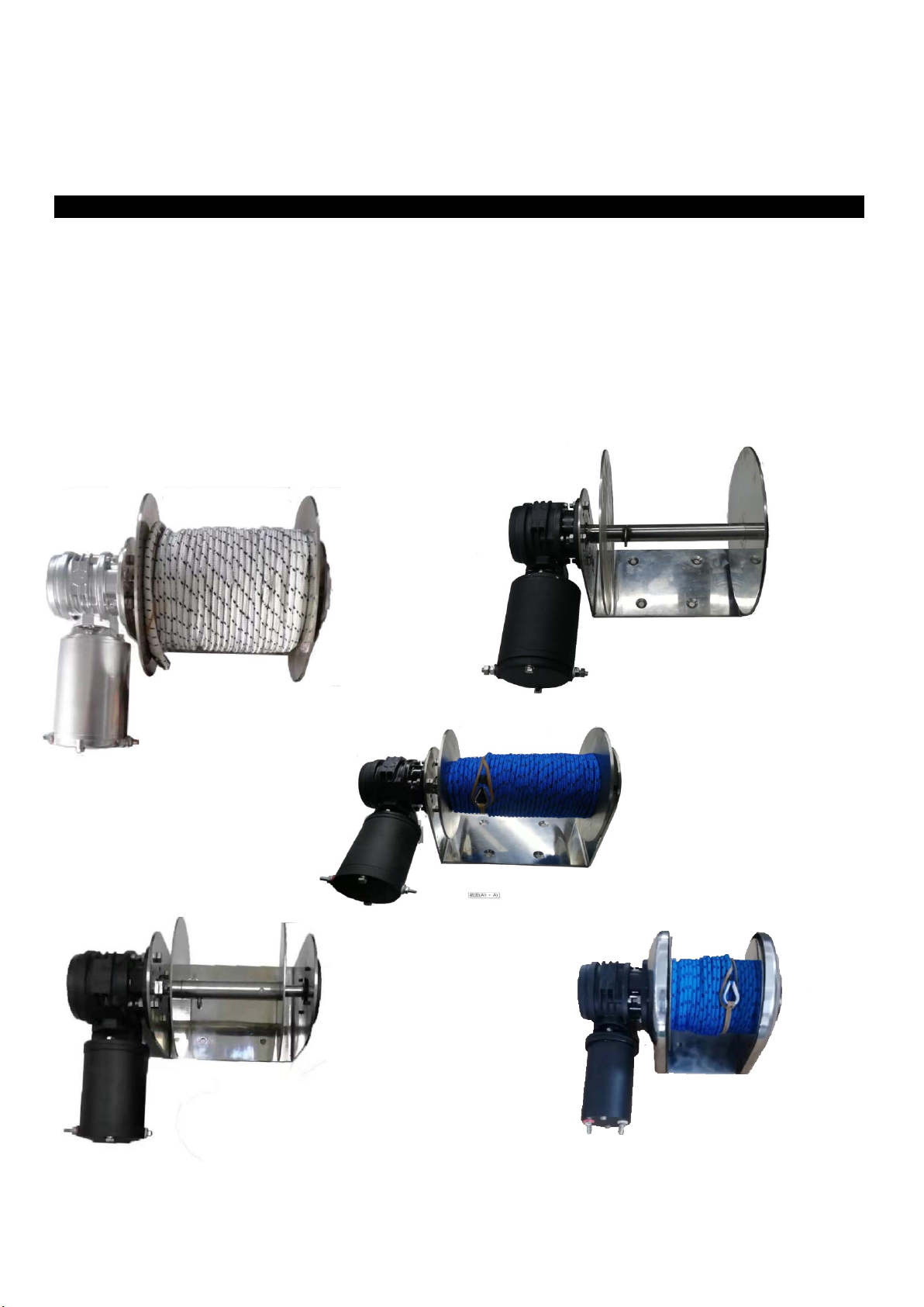
Installation and Operating Instructions
Please read and save these instructions. Read carefully before attempting to assemble, install, operate or maintain this anchor
winch. Protect yourself and others by observing all safety information. Failure to comply with instructions could result in personal
injury and/or property damage! Retain instructions for future reference.
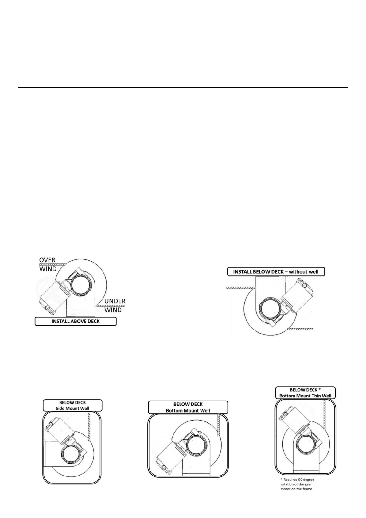
Unpacking - When unpacking, inspect carefully for any damage that may have occurred during transit. Make sure the winch is
correctly installed before putting unit into service.
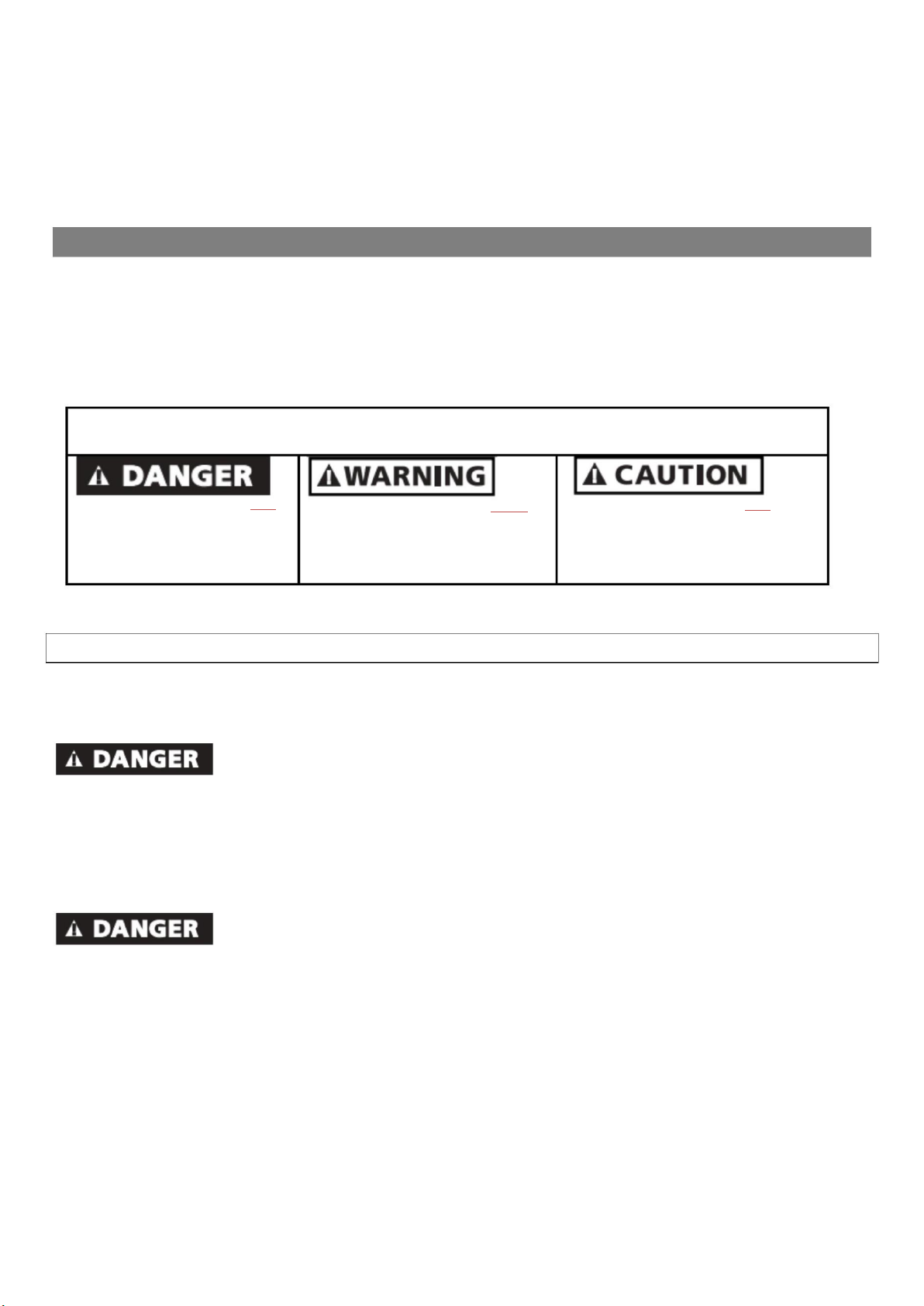
GENERAL SAFETY INFORMATION - Throughout this manual potential safety hazards will be noted with the following
terms. Please read and understand these terms before operating the product.
Danger means a hazard that WILL
cause death or serious injury if the
warning is ignored.
Warning means a hazard that COULD
cause death or serious injury if the
warning is ignored.
Caution means a hazard that MAY cause
minor or moderate injury if the warning
is ignored. It may also mean hazard that
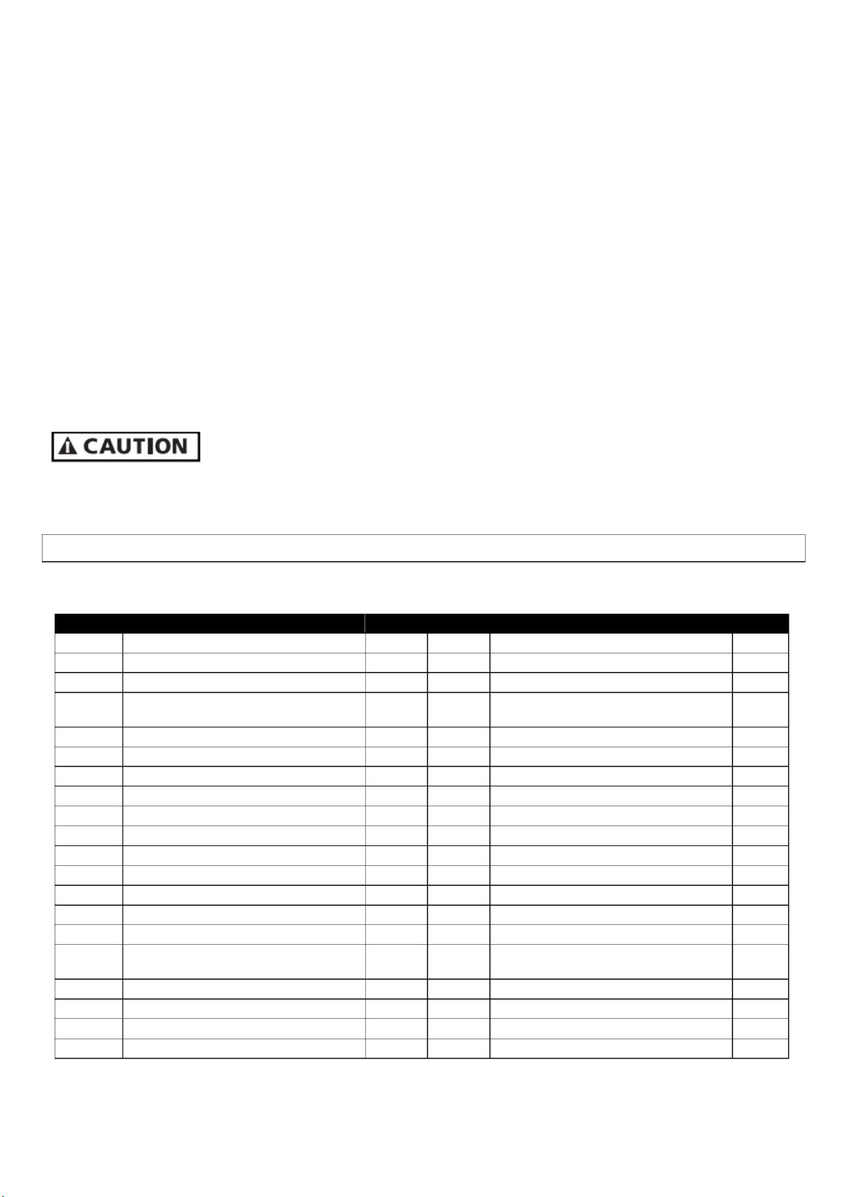
will
only
cause
damage
to
property.
SAFETY ISSUES
Read this user manual carefully. Be thoroughly familiar with the controls and the proper use of the equipment. Only persons well
acquainted with these rules of safe operation should be allowed to use the winch.
Rope breakage.
1. Never allow anyone to be positioned between the anchor and the winch. If the rope breaks it could snap back with enough
force to cause injury.
2. Never substitute cable for rope. Cable is not an acceptable anchor line as it does not stretch and is easily frayed. If cable
breaks it can snap back with more force than a rope.
3. This product is intended to lift typical marine anchors. Do not attempt to lift or move people or other objects.
4. Inspect entire rope for weakness, wear or kinking (short tight twist or curl) before each use. Replace worn rope.
Electrical shock and fire hazards.
1. If possible, do not extend the battery wires, doing so can reduce winch performance. If you can shorten the wires, this will
improve performance slightly. If you must extend the wires, wire selection must be made based on AWG wire size selection
charts for 100 amp circuits.
2. Wire that is too small could result in overloading and a fire. Larger gauge wire will improve product life. Use 4 AWG 105c
wire up to 15 ft. (4.6m), 2 AWG 105c wire up to 25 ft. (7.6m). Splice the additional wires directly to the wires coming out of
the winch CU (Control Unit). DO NOT open the CU and try to replace the existing wires with heavier wire. Warranty will be
void and a satisfactory result will not be attained. Cut the existing battery wires about 12 inches (30cm) from the CU and
splice to extended wires with a sealed connection.
3. Opening the Control Unit will void the product warranty unless instructed by a TRAC Service Technician.
4. Use a 100-amp circuit breaker or fuse near the battery. This breaker protects the wire between winch and battery.
5. Make sure any crimped electrical connections do not pull apart easily.
6. Always disconnect the battery positive wire from the battery before attempting to install, relocate, or service the winch.

Boat trailering hazards – As a precaution, when the boat is being trailered, the anchor must be secured
inside the boat or tow vehicle. If the anchor were to break free while trailering, it could cause serious damage and/or injury.
Anchoring hazards.
1. Damage to the winch WILL occur if operator drives boat while anchor is down. Dragging the anchor will damage the winch.
2. Do not exceed the capacity of the winch. If the circuit breaker halts operation of the winch during retrieval or deployment;
the winch may have been overloaded. The winch Control Unit, located on the winch motor, has an internal circuit breaker
to prevent damage from overload. If tripped, the circuit may be reset at the switch by pressing the RESET button. A second
circuit breaker (or fuse) is to be located at the battery for proper installation.
Entanglement hazards.
1. Never place any object or tool in the rope spool while retrieving or deploying the anchor. The tool or object could become
tangled in the rope resulting in serious injury and/or damage to the winch.
2. Do not wear loose fitting clothing, scarves, or neck ties during the operation of the winch. Loose clothing may become
caught in moving parts resulting in injury or death.
3. Do not operate the winch if any person is near the rope or rope spool.
4. Do not operate the winch under the influence of drugs and/or alcohol.
Storage and Maintenance – For storage, it is best to disconnect positive wire from battery.
WINCH DESCRIPTION
This drum winch retrieves and deploys anchors using rope and up to 20 feet of optional chain. This anchor winch features power-up,
power-down, Free Fall Down and ON/OFF operation. All operations are located on two control switches. One switch is located on
the Control Unit for easy operation at the winch itself. A second switch may be located at the helm, or anywhere the installer
chooses.
PRODUCT SPECIFICATIONS
TW240/1000W TW200/TW180
Maximum Rode Weight 60 lbs. (27kg) 60 lbs. (27kg)
(weight of the anchor, line, chain)
Line speeds:
Power Down 65 FPM (20m) 70 FPM (21m)
Power Up 55 FPM (17m) 60 FPM (18m)
Winch Dimensions:
Motor at 30 degrees L 14” x W 15” x H 12” L 12.5” x W 13” x H 9”
(35.6cm x 38.1cm x 30.5cm) (31.8cm x 33cm x 24cm)
Motor angled upright L 10” x W 15” x H 14.5” L 10” x W 13” x H 13.5”
(25.4cm x 38.1cm x 36.8cm) (25.4cm x 33cm x 34.3cm)
Other Specifications:
Permanent magnet 1800 watt DC Motor, 12V nominal
Normal operation will use 20-70 amps. Current limited at 120 amps.
Frame, drum, and hardware made from marine grade stainless steel
Sealed 4-gauge battery lead wires 6’ (2m)
Mounting Bolt Pattern (LxW): 4-3/4” (120mm) x 3-1/2” (90mm), 4 bolt staggered

INSTALLATION
TOOLS REQUIRED:
1. Electric Drill with 7/8” (22mm), 5/16” (10mm) and 1/8” (3mm) Drill Bits
2. Adjustable (Crescent style) wrench
3. Socket and driver
MATERIALS REQUIRED
1. Mounting Hardware - For1000w/ TW240use countersink head bolts – for TW200/TW180use hex head or round head bolts.
4 sets- 5/16 (10mm) stainless steel bolts (length = mounting surface + 1.5” (40mm), washers, and lock-nuts.
2. Wire – if longer than 2 meters is required.
INSTALLING ANCHOR WINCH ON BOAT DECK
The anchor winch can be installed above or below deck. It is important that the anchor roller line up with the centerline of the rope
drum for proper loading of rope. To install the anchor winch, follow these steps.
1. Place the winch in location and directly inline and centered with the anchor roller.
2. Examine both sides of the installation surface for obstructions to bolts and wire routing.
3. Mark the winch bolt locations and wire holes if any are required.
4. Remove winch, drill necessary holes, seal holes with marine grade silicone sealant.
5. Seal the exposed deck material inside the hole with marine silicone sealant.
6. Secure the winch to the deck. Consider using large fender washers and backer board under the deck to ensure the
greatest strength and to spread the load.
INSTALLING ANCHOR WINCH IN THE ANCHOR WELL
Identify location of winch, battery wire and switch wire. Follow steps 1-7 to install. If installing in a narrow anchor well, it might be
necessary to rotate the gear-motor 90 degrees as shown. To rotate the gear-motor, remove battery positive wire from battery. At
the winch location, snip and remove plastic wire ties around the wire harness to make added wire length available. Locate the bolts
holding the gearbox to winch frame. Remove nuts, remove bolts, rotate gear-motor (without removing gear-motor) to the desired
location. Reinsert bolts, attach and tighten the nuts. Group extra wire in a bundle and secure with new plastic wire ties.

INSTALLING THE SWITCH PANEL
This winch includes a second switch and connector cable. Determine the location of the second switch (usually at the helm). Hold
the switch in the desired location and mark the center hole location and drill a 7/8” (22mm) hole for the connector to pass through.
Pass the switch connector through the hole and lay the switch flat on the installation surface. Align to switch, mark four screw holes,
remove switch. Drill the four marked screw holes with 1/8” (3mm) drill bit. Route the connector cable between winch and second
switch location. Install switch with four self-tapping screws provided. Excess cable can be coiled and tied off with plastic cable ties.
THE CIRCUIT BREAKER
This winch includes over-current circuit protection to protect the winch from overload. An additional 100-amp circuit breaker or
fuse is recommended to protect the battery wire between the winch and battery. Position for the fuse or breaker close to the
battery.
WIRING SELECTION & SPECIFICATION
Using incorrect wire can result in overloading and a fire. Using incorrect circuit breakers may result in melting of wire insulation and
possibly a fire. DO NOT use electrical wire sizes smaller than recommended in AWG wire selection charts. Larger gauge wire will
improve product life. Use 4 AWG up to 15 ft. (4.6m), 2 gauge up to 25 ft. (7.6m). Always use larger wire if you can.
Always disconnect battery positive wire from the battery before attempting to install, relocate, or service the winch.
Make sure all crimped electrical connectors meet industry standards.
Follow order of wiring steps to ensure power is not applied to winch until wires and circuit breakers are installed.
Keep wires away from intense sources of heat. Be sure newly installed wires are away from any bare wires.
Never attach the circuit breaker to the negative terminal of the battery.
WIRING
Route the battery wires between winch and battery. Connect the RED positive (+) wire to the LOAD side of the circuit breaker.
Connect the BLACK negative (-) wire connects to the battery negative terminal.
ROPE TO DRUM ATTACHMENT
Route the rope through the davit or anchor rollers to the winch drum. Insert the rope through the metal loop located on the drum
center tube, wrap the rope around the drum center tube and tie in a knot. Pull the rope to confirm your knot is holding as well as
you require. Make sure the rope is not tangled and not looped around anything and is free to wrap on the spool. If no rollers are
present, hold the rope on center of drum about 3 to 6 feet away. While holding light to moderate rope tension, ask a mate to press
the “UP” direction on the switch and hold UP button until the rope is wrapped on the drum. Release the switch button at any time
during the rope loading process, to pause, or if an unsatisfactory wrap is occurring. The installer may wish to load the rope “level-
wind” manor (wrapping the rope back and forth in neat rows on the drum), however when the winch is normally used for anchoring,
the rope will wrap on the drum in a random manor. Wrapping in a random manor will give you a true sense of when the drum is full
and no additional rope or chain will fit. When the rope or chain makes contact with the frame under the drum, no addition rope or
chain will fit without causing the free-fall to stop working correctly.
ANCHOR CHAIN TO ROPE ATTACHMENT
Use a threaded link to attach rope eye-splice to chain and chain to anchor. Some shackles can interfere with anchor docking.

RODE RECOMMENDATIONS
BOAT WEIGHTS BOAT LENGTHS
Light Boat 20'–24' 24'–28' 28'–32' 32'–36' 36'–40' 41'–45'
Medium Boat 16'–20' 20'–24' 24'–28' 28'–32' 32'–36' 36'–40'
Heavy Boat 12'–16' 16'–20' 20'–24' 24'–28' 28'–32' 32'–36'
TRAC MODEL RODE DIAMETER OPTIONS
3/16" 1/4" 9/32" 5/16" 3/8" 1/2"
(5mm) (6mm) (7mm) (8mm) (9.5mm) (12.5mm)
9/16"
(14mm)
5/8"
(16mm)
1000W/TW240 700 ft ^ 500 ft* 330 ft* 300 ft*~ 200 ft* 100 ft * 60 ft ^ 40ft ^
TW200/TW180 400 ft ^ 300 ft* 200 ft*~ 180 ft* 120 ft* 100 ft ^
* plus 20 ft. of chain
+ plus 15 ft. of chain
^ no chain
SAFETY CABLE ATTACHMENT
When the boat is being transported by trailer, the anchor must be placed in the boat and secured. If the anchor were to break free
during trailering, it could cause serious damage and injury. An anchor safety cable is only designed to hold the anchor in place when
the boat is underway in the water and is an insufficient safety measure while trailering your boat.
It is the responsibility of the boat operator to assure the anchor is safely secured each time the anchor is retrieved. The operator
may optionally install an anchor safety cable for use while the boat is underway.
DRUM WINCH OPERATION
UP/DOWN – To lower the anchor, press and hold the button with the downward pointing arrow. Release the button when you wish
to stop letting rope out. To raise the anchor, press and hold the button with the upward pointed arrow. Release the button when
the anchor is docked or when you wish to stop the retrieval of the anchor.
Helpful hints:
1. After the anchor is deployed, avoid using the DOWN button to let rope out. Excessive powering down could create a rope
tangle. A better technique is to use FREE FALL to let more rope out.
2. Keep all surfaces clean using water, mild environmentally safe cleaners and a soft cloth. Do not use abrasive cleaners.
TROUBLE SHOOTING GUIDE
Loading the rope and chain:
If there is a buildup on one side of the drum, the winch has been installed off-center. The drum must be both centered and
square to the roller or davit. Build up to one side of the drum indicates drum is not on center or not square to the roller.
If when retrieving the anchor, the drum becomes filled and the rope or chain contacts the bottom frame of the winch, you
have exceeded the drum capacity.
Anchor fails to fall
Press the DOWN switch is activated, confirm the anchor will deploy normally.
Press FREE FALL to confirm drum is released and free to spin.

Over-run
If the rope tangles or spills over the side of the drum, apply tension on the rope while pressing the UP or DOWN button in
the appropriate direction to unwind the tangle.
Actuator Malfunctions
Check for power present on the connector (CU side) when unplugged and FREE FALL or LOCK buttons are
pressed. Check electrical connector.
Clean any salt build
up. No Power
Check reset LED button on switch. Reset if needed.
Check electrical connections.
Confirm battery power is
present. Breaker Trips
If the anchor is stuck on the bottom and you hold your finger on the UP switch, the circuit breaker will trip. Reset the circuit
breaker, drive your boat toward the anchor, and press the UP button when the rope becomes slack.
It is customery to maneuver the boat closer to the anchor when raising the anchor. Care must be taken
to NOT drag the anchor with the boat’s power. This will cause product damage or injury. Do NOT use the anchor winch to pull the
boat to the anchor position. Motor the boat toward the anchor while retrieving the anchor rope.
DRUM WINCH PARTS
If ordering a part, provide the product model as well as the part number.
PART # DESCRIPTION QTY PART # DESCRIPTION QTY
1 Spool 1 21 Bearing Cap 1
2 Frame 1 22 Screws for Bearing Cap 4
3 Gear Motor 1 24 Cotter Key 1
Washers
4 Gear Motor Mounting Screws and 4
6 Gear Motor Output Shaft Bearing 1
10 Warning Label 1
11 Output Shaft 1
12 Screw for Actuator Plate 1
13 Bushing 1
17 Set Screw 1
18 Spool Tube 1
19 Bearing for Spool Tube 1
20 Retainer Ring 1

1000W TW240 TW200 TW180
22
20
12 18
14
2
3
3 4 21
19
17
6
11
9 & 10
13
5
2
TW180
1
3
4
22
17 21
24
5
12
2
6
11
13
18
19 20 23
This manual suits for next models
3
Table of contents
Popular Winch manuals by other brands

ADFINIS
ADFINIS SKYLOCK user manual

Clarke
Clarke Strong-Arm CHP 250 Operating & maintenance instructions

Pullmaster
Pullmaster M50 Instructions and parts manual

Ingersoll-Rand
Ingersoll-Rand Man Rider LS2-150HLP Series Product Maintenance Information

Lewmar
Lewmar OCEAN Series Owners installation, operation & servicing manual

Comeup
Comeup HV-8 instruction manual