Vgate ECU-PRO Vgatescan VS-890 User manual

\r
I
E
r
=
\
u
$
tr
trE
trs
tri
jI
Ut
utI

Welcome!
Thank you for buying Vgatescan OBDII Diagnostic
Scanner!
The Vgatescan OBDII Diagnostic Scanner allows you to
access your OBDII vehicle's data. Vehicle data, which was only
available to dealership technicians using expensive proprietary
scan tools, is now available to every people who has a Vgatescan!
Vgatescan is the prime choice for users keen on DlY.
a Scanners support 13 protocols and you can use two modes
to scan which includes Auto scan mode and Manually scan
mode;
a Vgatescan tool can support from model Sl to modelS 9;
a .More than Tl vehicle manufacturer built-in for you.
O DTCs include Generic (P0, P2, P3, B0, U0 and C0) &
manufacturer specific (P1, P3, BL,9.2, Ul and CL,Cz,l codes.
O 80 percent trouble codes have help information in scan tool.
o Scan tool has Black Mask OLED. You can read the content of
scanner smoothly when in strong light.
O DTC definitions are written in user friendly words rather
than obscure technical terms.
t1I

- Read Diagnostic Trouble Codes (DTCs)
- Clear trouble codes
- Vieiv real-time vehicle operation data (Data stream)
- View Freeze Frame data
- View l/M readiness
-Read 02 Monitor Test data
-Read On-Board Mon. Test
-Component Test
-View the vehicle's information
The Vgatescan OBDII Diagnostic Scanner is the perfect
scan tool to make you diagnose a problem more easily!
Table of Contents
tzt t3I

5.4 Freeze Frame ...'..'..'..45
5.5:/M Readiness ..,.-......47
5.6 O2'Monitor Test..... ...............'.'....49
5.7 On-Board Mon. Test ........... ..'......51
5.10 Modules Present.... .................'..57
5.11 Unit of Measure '.....58
5.12 State Emission..... .......'.......'......'59
5.Appendix ..........60
Appendix 1-PlD List.... .......'........'.'.'...60
Appendix 2 ln-use Performance Tracking Data .'...".......'.."'...69
Appendix 3 l/M Readiness 1ist.............. ..........,..74
Appendix 4 Vehicle Manufacturer........'...... ....,.75
Appendix 5 Special abbreviation of Vgatescan.....'.....'..... .... - -.78
7. Warranty and Service .....'...79
7.1 Limited One Year Warranty .--......79
7.2 Service Procedures .........'..'.........80
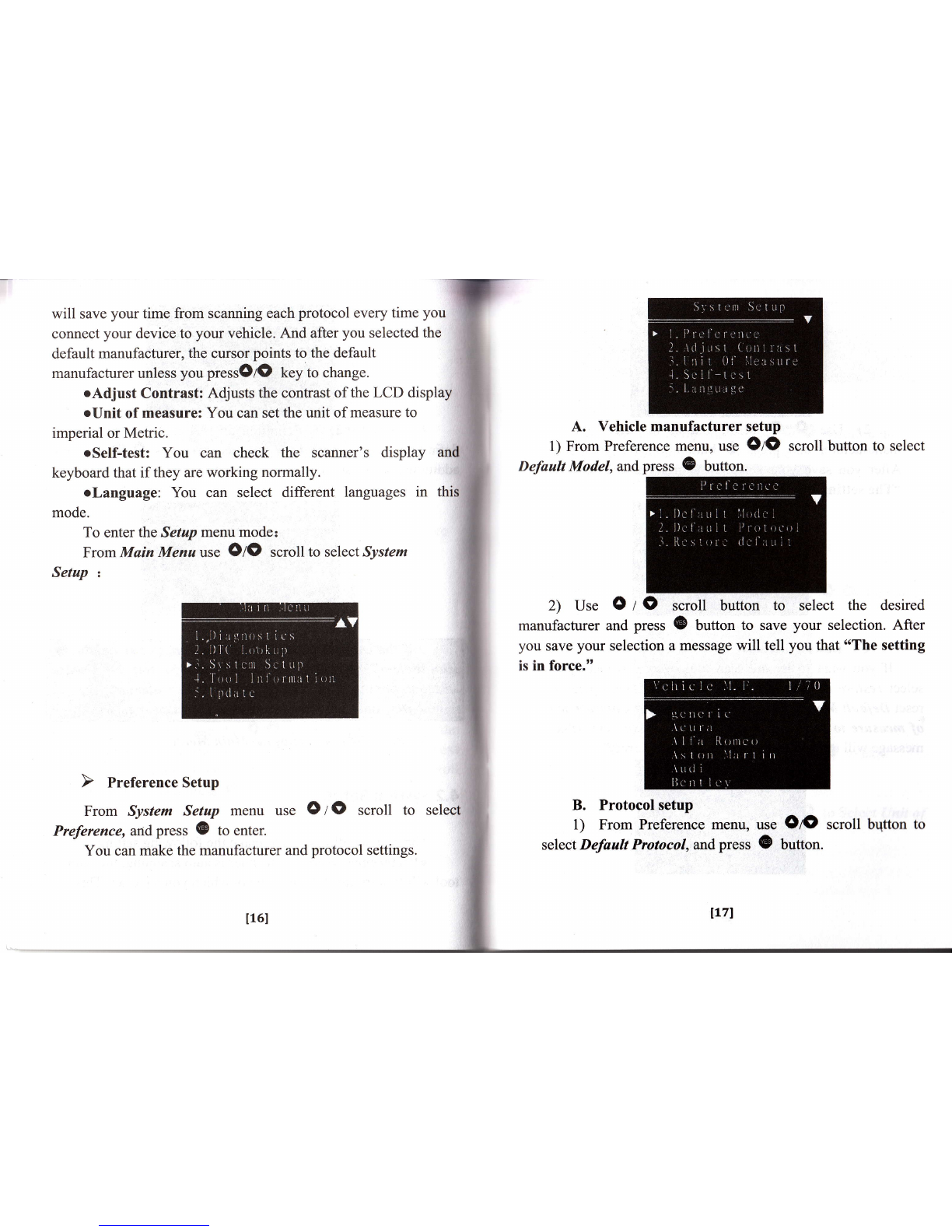
1. Safety Precautions and Warnings
For your Health and Safety, please read this manual
thoroughly before using your Scan Tool. First, you should read
the safety precautions and warnings. Safefy messages are
provided to help prevent personal injury and equipment damage.
EwAANTNGI
l-^l
twl
o Do not drop or shock the scan tool.
o Overpressure can cause damage on liquid crystal display
(LCD), and it can also provoke malfunction because of its
own feafures.
a Do not connect or disconnect any test equipment with
ignition on or engine running
a Operate the vehicle in a well-ventilated work area; exhaust
gases are poisonous
o Users should not remodel or take the product apart by
themselves.
a Do not use fuel injector cleaning solvents when performing
diagnostic testing
o Do not place tools or test equipment on fenders or other
places in engine compartment
o Use the scan tool only as described in the user's manual
o Follow service manual warnings when working around air
bag components or wiring
o Do not leave a running engine unattended.
o Keep code reader dry, clean and free from oil, water and
grease. Use a mild detergent on a clean cloth to clean the
tst
t4l

outside of the tool.
o Engine systems that malfunction can cause injrrry
Acnurou
this manual cannot cover all possible conditions
and situations that may occur. lt must be
understood that common sense and caution are
factors which cannot be built into this product, but
must be applied by the operator.
2. General lnformation
2.1 About On-Board Diagnostics (OBD) ll
What is OBD ll?
On-board diagnostics version II (OBD II) is a system that
the Society of Automotive Engineers (SAE) developed to
standardize automotive electronic diagnosis. Beginning in 1996,
most new vehicles sold in the United States were fully OBD II
compliant.
The OBD II system is designed to monitor emission control
systems and key engine components by performing either
continuous or periodic tests of specifi-c components and vehicle
conditions. When a problem is detected, the OBD II system turns
on a warning lamp (MIL) on the vehicle instrument panel to alert
the driver typically by the phrase of "Check Engine" or "Seryice
Engine Soon". The system will also store important information
about the detected malfunctioll so that a technician can accurately
find and fix the problem. Here below follow three pieces of such
valuable information:
1) Whether the Malfunction Indicator Light (MIL) is
commanded ON or OFF;
2) \Mhich, if any, Diagnostic Trouble Codes @TCs) are
stored;
3) Readiness Monitor status.
Does My Car Have OBD-ll?
171
t6I

All cars and light trucks built and sold in the United States
after January 1,1996 were required to be OBD II equipped. In
general, this means all1996 model year cars and light trucks are
compliant, even if built in late 1995.
Two factors will show if your vehicle is definitely OBD II
equipped:
1) There will be an OBD II connector.
2) There will be a note on a sticker or nameplate under the
hood: "OBD II compliant".
2.2Data Link Connector (DLC)
What is DLC?
The data link connector (DLC) allows the Scan Tool to
communicate with the vehicle's computer(s). Before OBD II,
manufacturers used different DLC's to communicate with the
vehicle. Use the proper DLC adapter cable to connect the Scan
Tool to the vehicle. Also, the vehicle's DLC may be found in
several different places and have many different configurations.
14213 I4l5I6I7I8
I 110111112I13I14 '!6
Where is the connector located?
The connector must be located within three feet of the driver
and must not require any tools to be revealed. Look under the
dash and behind ashtrays.
2.3 Diagnostic Trouble Codes (DTCs)
DTCs are codes that are stored by the on-board computer
diagnostic system in response to a problem found in the vehicle.
They are used to help determine the cause of a problem or
problems with a vehicle. DTCs consist of a five-digit
alphanumeric code such as PI260.
I9I
t8t

Example of Diagnostic Trouble Code 3, About Vgatescan
3.1 Scan Tool Description
1.LCD DISPLAY: Indicates test results. Backlit, 128 x 64
pixel display with contrast adjustment.
2. (E: Press(Dto confirm or enter the next menu. You can.
press(Eto selected/ deselected items in the "Customize data set"
of "Data stream" and, "Freezeframe" .Hold@to enter the
selected items.
P1260
P: Power train
C:Chassis
8: Body
U: Network
ldentifying specific malf unctioning
section of the systems
CodeType
Generic (SAE):
P0, P2, P34-P39
80, 83
CO, C3
u0, u3,
llan ufecturer Spcific:
P1, P30-P33
81, 82
cL,c2
Ul, U2
Vehicle Specific System
IlOI t11l

3. @: Cancels a selection from a menu or returns to the
menu. It is also used to reset code to P0000 in the DTC Lookup.
+. OtO: moves up or down through menu and submenu
items. Hold up or down to read the previous/next page. If you
keep holdingOlOtey it can change page automatically. When
looking up DTC, it is used to change value of selected character
and hold up or hold down to select the digit which needed to be
changed.
5. 9: Pressgto read the help information when o'?" icon
observed on the upper of the screen.
6. O: Hold3to return to Main Menu and pressOto retu
to Main Menu when looking up DTC.
3.2Navigation Characters
Characters used to help navigate the scan tool are:
l) ">" -- Indicates current selection
2> * Llf " -- If the current screen has more than one item
you can choose, etllf n wil be displayed on the upper of the
screen, it means that scroll up/down is available.
3) "?" -- It indicates help information is available. Press
ebutton to view help information of the selected item.
4) "$" -- Means the control module address from which the
data is retrieved.
5) "xx/yy"--The number "yy" to the upper right corner of the
screen indicates total number of items under this menu and "xx"
means current sequence of cursor")"pointed. When the message
information more than one screen, "yy" means total number of
pages and "xx" is current page.
3.3 Scanner power
The power of the scan tool is provided via the vehicle Data
Link Connector (DLC). Just follow the steps below to turn on the
scan tool:
l) Find DLC on vehicle.
2) Connect the scan tool and diagnostic connector with the
cable supplied.
3.4 Suggestions for users
l) Please do not use solvents such as alcohol to clean
the keyboard or display.
2) Please use a mild nonabrasive detergent and a soft
cotton cloth
3) A plastic DLC cover may be found for some
vehicles and you need to remove it before plugging the
EOBD cable
4. Using the Scan Tool
4.1 DTC Lookup
The DTC Lookup function is used to search for definitions
of DTCs stored in the Scan Tool.
1).Enter DTC Lookup:
From the Main Menu, useO/Oto select DTC Loohup and
I13I
1L2l

press@to enter.
2).From DTC Lookup menu,hold OIO to move to the
clesired character, press Ol0 button to change selected
character and press {B button to confitm. If you want to change
the code to P0000, you can press @ key to clear the code.
3) Before you read the DTC dcfinition, you must select the
vehicle manufacturer" usc thc OIO scroll buttons to sclect the
vehicle manufacturcr and hold OzO to view previous or next
screen. You can also kccp holding Oloto automatically scroll
up and down. Then prcss @ to view the DTC definition.
4) View the DTC definition on screen. When the DTC's
tlcflrnition covers more than one screen, press OIO to view
rrtlditional information on previous/next screens.
4.2 System Setup
The scanner allows you to make the following settings:
oPreference: When the scanner is auto scanning, thc scurr
tool will first try the default protocol which you havc sct. 'l'[ris
114l
5 ) Press @t.y to return to Muin Menu.
llsI

will save your time from scanning each protocol every time you
connect your device to your vehicle. And after you selected the
default manufacturer, the cursor points to the default
manufacturer unless you pressOlO key to change.
oAdjust Contrast: Adjusts the contrast of the LCD display
oUnit of measure: You can set the unit of measure to
imperial or Metric.
oSelf-test: You can check the scanner's display and
keyboard that if they are working normally.
olanguage: You can select different languages in this
mode.
To enter the Setap menu mode:
From Main Menuuse O/O scroll to select System
Setup t
A. Vehicle manufacturer setup
l) From Preference menu, use OIO scroll
Defautt Model, andpress (D button.
2) Use OrO
manufacturer and press
you save your selection
is in force."
scroll buffon to
G button to save
a message will tell
button to select
select the desired
your selection. After
you that "The setting
From System Setup menu use O I O scroll to
Preference, and press (D to enter.
You can make the manufacturer and protocol settings.
B. Protocol setup
1) From Preference menu, use OIO scroll
select Default Protocol, and press O buuon.
select
lLTl
t16l
bqtton to

2) Use O I O scroll button to select the desired
manufacturer and press (B button to save your selecti
After you save your selection a message will tell you that
"The setting is in force."
C. Restore default
If you want to let the scan tool restore to factory setting,
select restore default and press @ button. This operation will
reset Default Model, Defoult Protocol, Adjust Contrast and Unit
of measare to factory settings. After you save your selection a
message will tell you that o'The setting is in force.,,
1) From System Setup menu use OtO scroll button
select Adjust Contrast and press (E to enter.
2) From Adjust contrast menu, use OrO button
increase or decrease contrast.
3) Press @ to save your settings and press 0 to exit.
1) From System Setup menu use OIO to Select ltnit of
Measure andpress (E to enter.
l18l tlel

2) From Unit of Measure menn, use OIO scroll button to
select the desired unit of measurement. The Unit of Measure ig
used in Data stream; Freeze Frame and On-Board Monitor Test"
Self-test,and press (& to enter.
A. Display Test
1) Select Display Tbst fuom Device Self-kst menu and press
button to start display Test.
2) Please pay attention to the LCD. Look for Missing Spots.
3) You can press any key to exit the test. Hold any key also
can exit the test.
B. Keyboard Test
The Keyboard Test is used to veriff keys are working correctly
l) Select Keyboard Tbst from Device Self-Test menu
and press G button to start display Test
o
3) Press (B to save
selection a message will
force."
your choice. After you save your
tell you that "The setting is in
The Tool self-test function checks if the display and
keyboard are working properly.
From System Setup menu, use OIO scroll button to select
1201 121l

T-
2) In this test you can press any key to check thc
keyboard. when you press a key, the corresponding icon will
twinkle. If the corresponding icon does not twinkle, then the
key is not functioning properly.
3) After your selection, it will return to system setup. And
llrc screen will display in the selected language.
4.3 Tool lnformation
The Tool Information function allows viewing of some
irnportant information such as serial number and software version
rrrrmber of the scanner.
1) From Main menu, use OIO scroll button to select
Tool lnformation and press (B to view.
to Select
button to select different Languages and press ::
View tool information on screen.
Press @ key to return.
2)
3)
2) Use Olo
@to confirm.
i:
?:
;
.i
$-
3) Hold @to rerum.
l) From System
Languageandpress @Setup menu use O Z O
to enter.
Izzl l23l

4.4 lnstalling the USB Drivers & PC Update
I ) Install:
- Please connect the Vgatescan USB cable to your
and then there will be a dialog window popped up titled 66
New Hardware Wizard".
Select '6No, not this time" and then click "Nexf' button
continue:
Select "Install from a list or specific location (Adv
and then click "Next"button to proceed:
Check the "Include this location in the search" checkbox
irnd click "BFohtse" button. A standard o'Browse for folder"
dialog will show up, and you need to choose a specific folder
according to your operating system.
When select specified file is done, the file's name will be
displayed in the browser location as follow Choose a proper
lblder and click $OK" to close the dialog. Now there will be
some text indicating the location you have just chosen beneath
lhe "lnclude this location in the search" checkbox as shown in
the following picture.
Welcom6 to the Found l{*
Hadw3 Wizild
vl&dtd6ddl#tub
dqopd@,6e*e.l.&O, d6
hWtu&w6*lssFlrMl
kglee
bv,fuffib\^/i*!&r'db
124l 125I

Compleling the Found Nil
Ha,dwa,e Wizald
Ih NqdhJ,n*d nnfuh.dr!.,. rd
;/ use.s""c*""'
kFBhberh{ad
cid_-l
' l:'lt::: ;iii,jy :, . :r ..,,::*ts -l{ryl __cr.dJ,l
After installation, a balloon wills pop-up on the bottom of
Click "Next" button to start installing the driver.
When install the software is complete, please click "tr{
button.
Now, a dialog named 'oCompleting the Found N
Hardware Wizardl' will show up. It means the wizard
finished installing the software for USB to serial Comm.
Please click "Flrisft" button to close the wizard.
thc screen as shown in the following picture.
The Driver installation is complete now!
2) Setup
Right click on the "My Computer', from desktop. Select
"Manage" and click the left mouse button to enter.
Click the left mouse button on the "Device Manger,, from
Computer Management, and then search the specified port which
l27l
126l

rused to update. Left click "Device Manger" and click the + sign
on the left of the Port icon.
"Prolific USB-to-Serial Comm Portable (COM7)'is the
port which used to update. Please note: the setup of this
port must be same with the one which used in PC update, if
are different, the PC update will fail to connect to your device.
If the default port is beyond the one which is used in PC
update, you need to setup the COM number manually as
following:
Click the right mouse button on the *Proliftc USB
Comm Portable rcOM7 ) ", and select oProperties" to enter.
Select uPort Settings" on the Prolific USB-to-Serial Comm
l)ortable ( COMT ) Properties as follow, and then click the
"Advanced" button to enter.
Select the port from COMI to COM4 to be
port used to update.
Please note: this port must be same with the
update.
the specified
one used in PC
When you have selected a port, click nOK" button. Now, setup
is completed!
l28l lzel

i . nmccan.lrrgflooP PC upoArt
-srr$nrq
I u-r-,[6! N,.lffi=
- r-ii66nrr r-;, I
From "Main menu",
and press @ to start. use O/O button to select "Opdate"
3) PC Update Operation
You can update your scan tool from our web to add trouble
codes and vehicle manufacture. To update your device
successfully, please read the following information carefully
before you want to update your scanner.
"1, Please make sure the firmware and device you use to
update comes from authorized distributors.
2. Make use of any pirated firmware may cause lock-up
to your device.
3. Keep the power supply stable during update,
otherwise this operation will cause serious damage to your
device."
After the driver installed, start the PC Update software, do as
the following steps:
Select the specified port and baud rate which has
been setup.
When you have
will be displayed
your device.
entered, some warning information
first. Press @ if you want to update
Press @ key to exit, and press @ to link to PC.
t30l t31l

If you press 0 key during linking, update will be ca
and then Vgatescan will tell you that "The update had been
canceled. Press NO key to back".
Press "Srcrr" button on your computer. After the
connection is established, you can learn the progress of
update from the two status bars in the device and the PC.
After update, the number of trouble codes or vehicle
manufacturers will be increased. You can check these in "DTC
LOADED" in Tool information and nYehicle M.E" in DTC
lookup.
AcRunoru
If update is succeed. A message will display
that "Update Succeed! Now you can turn
device"
to tell
132l
off your
t33l

5. OBD ll Diagnostics
From Main menu, use O z O scroll button to select
Diagnostics and press @ to enter.
Before scan protocol, you should select a scan
Vgatescan scan tool has two scan modes which are
and Manually Select.
diagnosed.
protocol and press{B. The scan tool will links to the vehicle
with the protocol you have selected.
If the scan tool fails to communicate with the vehicle,s ECU
(Engine control Unit) ,A *Link Error!" message shows up on the
display. You must make sure the following things:
D The vehicle is OBD compliant.
D Tttrn the key ON with engine OFE
D DLC is firmly connected.
D The integrity of diagnostic wiring harness.
If the summary of system status (MIL status, Code found,
Monitors NiA, Monitors Ready, Monitors Not Ready) show up on
mode. The
Auto Scan
OBD ll protocols will be observed on the screen .When the
scan tool links to the vehicle, the communication protocol is
automatically detected, and is.used until another vehicle is
l34I tssl

the screen, it means link succeed.
Press {B to enter Diagnostic menu and press @ key to
return the Select Scan Mode.
When more than one vehicle control module is detected by
the scan tool, you must select the module where the data may bc
retrieved. The most often to be selected are the ENGINE and AT.
The Diagnostic menu includes the following modes:
C Read DTCs
D Clear DTCs
D Data stream
DFreeze Frame
tIllNI Readiness
D 02 Monitor Test
O On-Board Mon. Test
O Component Test
C Vehicle Information
D Modules Present
D Unit of Measure
D State Emission
5.1Read DTCs
You can read the trouble codes of your vehicle in this mode.
It irrcludes All DTCs, Stored DTCs and Pending DTCs.
l) Use OIO scroll button to select Read DTCs from
Diagnostic Menu and press @ to enter.
2) Use OIO to select All DTCs, Stored DTCs or
Pending DTCs form Select Operation Press (B to enter.
3) .View DTC List
After selected one item in
cnter the DTC List. the Select Operation yotr will
l37l
[36]
Table of contents
Popular Medical Equipment manuals by other brands

RJL systems
RJL systems QUANTUM V SEGMENTAL BIA user manual

Advantech
Advantech POC127 user manual

PROVOX
PROVOX Vega manual

Heart Sure
Heart Sure A380 Instruction manual & warranty information

Zimmer Elektromedizin
Zimmer Elektromedizin SonoStim Service

Ultrasound Technologies
Ultrasound Technologies Fetatrack 310 Service manual