VGE Blue-Lagoon BL530 User manual

UV-C and Pool equipment
BL530 PH/RX
DOSAGE SYSTEM
MEMBER OF:
TECHNICAL
MANUAL

EN
2| BL530 PH/RX DOSAGE SYSTEM
TABLE OF CONTENTS
CONTENT BOX 4
INTRODUCTION 4
INSTALLATION 4
TECHNICAL SPECIFICATIONS 5
FUNCTIONAL DESCRIPTION OF THE SYSTEM 6
HYDRAULIC CONNECTIONS
Suction Line 7
Injection Line 8
ELECTRICAL CONNECTIONS
Level Control 8
Flow Protection 9
INTERNAL CONNECTIONS FOR INSTALLERS ONLY 9
STARTUP 10
DISPLAY 10
OPERATION OF THE ELECTRONIC UNIT
Standard Configuration 11
Advanced Configuration 11
List of Configuration Parameters 12 - 15
Electrochemical Calibration 16 - 17
Manual Mode 17 - 18
CONTROL EXAMPLES 18
ERRORS / ALARMS 18 - 19
MAINTENANCE 19 - 20
ACCESSORIES AND SPARE PARTS 21 - 23
BL530 PH/RX DOSAGE SYSTEM

EN
BL530 PH/RX DOSAGE SYSTEM |3
UV-C and Pool equipment
WARNINGS
This manual is dedicated to the technical personnel responsible of the installation,
management and maintenance of the plants. The manufacturer assumes no
responsibility for damages or malfunctions occurring after intervention by
non-authorized personnel, or not compliant with the prescribed instructions.
Before performing any maintenance or repair action, ensure that the system is
electrically and hydraulically insulated.
Dispose of waste material accordingly with local regulations.
GENERAL SAFETY TIPS
WARNING! Before performing any operation on the pump, unplug the pump and
discharge the liquid from the pump head and tubes. Never operate on working pump.
During maintenance and repair of parts that normally become in contact with
chemicals, The pump has to be handled by qualified personnel only. Always use original
spare parts for maintenance.
Failure to follow instructions can cause damage to the equipment and, in extreme
cases, to people.
The manufacturer can modify the instrument or the technical manual without
advanced notice.
UV-C and Pool equipment

EN
4| BL530 PH/RX DOSAGE SYSTEM
BL530 PH/RX DOSAGE SYSTEM
CONTENT BOX
The BL530 unit is supplied already wired internally, and complete with:
1. BH08014 pH electrode with 2.5 m cable and BNC connector.
2. BH08015 redox electrode with platinum sensor, 2.5 m cable and BNC connector.
3. Two PVC electrode-holders with DN50 clamp for direct in-line installation of electrodes.
4. pH and redox calibration solutions, 90 ml bottles (pH4, pH7 and 220 mV).
5. Two standard kits for peristaltic pump, including suction and
delivery tubes, foot filters and injection valves.
6. Screws and stoppers for wall installation.
7. Instruction manual.
INTRODUCTION
BL530 is a compact system easy to install (wall) and maintain, which allows to monitor and control the
pH and redox potential levels in swimming pools. The BL530 system includes a digital controller which
operates accordingly with the set thresholds, two peristaltic pumps 4 l/h, pH and redox electrodes with
BNC connector, and probe-holders.
INSTALLATION
Warning! Always follow the warnings and general safety
information referred at the beginning of this manual!
Install the BL530 unit away from heat sources, in a dry place protected from direct sunlight, at a
maximum ambient temperature of 40°C. The minimum temperature shall be such as to ensure the
solution to be dosed remains in a fluid state and in no case less than that declared in the “Technical
specifications” section. The BL530 unit must be installed on a vertical wall and securely clamped
using the supplied screws and plugs. Or when it is necessary with the fasteners suitable to the
surface. Choose a location that allows easy calibration operations, use and maintenance. Place the
tanks of the products to be dosed below the pumps, without exceeding the maximum suction
height of the pumps (about 1.5 m). If the system is installed below the level of the liquid to be
dosed, check the condition of the injection valves. Take care of tightly closed chemical containers/
tanks. Chemical fumes may cause corrosion to the dosage system, the electronics and other
materials in this place.
Connect the connectors may be disconnected for packaging reasons to the respective
inputs on the bottom of the unit (see the “Functional description” section for further details).

EN
BL530 PH/RX DOSAGE SYSTEM |5
UV-C and Pool equipment
TECHNICAL SPECIFICATIONS
pH/RX Inputs Available on BNC connectors, input impedance > 10^12 Ω.
Measure Ranges 0.00 to 14.00 pH, 0 to 1000 mV (redox).
Precision Deviations less than 1% of the full scale
(when properly calibrated).
Precision Repeatability Better than 0.2% of the full scale.
Configuration Two configuration level (standard and advanced).
LEV Inputs 2 independent inputs for level sensors, available
on connectors, SPDT contact 5 V / 5 mA.
FLOW Input 1 input that can be used for connecting both the filter pump
contactor or the flow sensor (SPDT contact 5 V / 5 mA).
Serial Port RS232, available on external connector (optional).
Relay Output NO/NC configurable contact for alerting (optional).
Display Large alphanumeric, double row (x 16 characters) LCD, with backlight
Dosing Pumps Flow rate: 4 l/h @ 1 bar.
Materials: fiberglass reinforced PP pump head and fittings,
Santoprene (silicone upon request internal tube, PBT roller holder,
Delrin (self- lubricant) rollers. Max suction height: 1.5 m.
Power Supply Standard 230 V~, 50 Hz (other options upon request) ; 20W.
Protection Fuse F1A 5x20 (230V ~).
Environment Storage temperature -20 tot +60° C.
Working temperature -10 tot +40° C.
RH max. 90% non condensing.
Casing Self-extinguish plastic material with polyester front panel.
Installation Wall installation with supplied screws and stoppers.
Protection Rate IP65.
Dimensions 290 x 280 x 175 mm.
Weight Approx. 4 kg.
180
250
280
290
272
173
Ø6.5

EN
6| BL530 PH/RX DOSAGE SYSTEM
FUNCTIONAL DESCRIPTION OF THE SYSTEM
Front view
• Control panel with large display and
keyboard (see description on next page).
• Peristaltic pump for acid dosage.
• Peristaltic pump for chlorine dosage.
Bottom view: connections
• POWER Power cable (pre-wired).
• pH BNC connector for pH
electrode.
• RX BNC connector for
redox electrode.
• LEV1 Connector for level
sensor of tank 1 (acid).
• LEV2 Connector for level
sensor of tank 2 (chlorine).
• FLOW Connector for flow sensor.
BL530 PH/RX DOSAGE SYSTEM
Front panel
POWER LED Green light; slow flashing indicates that the unit is powered and
normally functioning, while fast blinking indicates a fault (lack of
liquid to be dosed or the pump is disabled).
OUT1, OUT2 LED Red light on during the rotation of the respective pump.
CAL Key Provides access to the “Configuration”, “Calibration” and “Manual
Mode” menus; confirms parameter modifications.
Key Scrolls the available menus/options; in calibration and
configuration modes decreases the displayed value.
Key Scrolls the available menus/options; in calibration and
configuration modes increases the displayed value.
ESC Key In calibration and configuration modes exits without
saving the modifications; from manual mode
resumes to normal operations.
ON/OFF Key Activate / de-activates the unit or confirms alarms;
both the disabled dosing or alarm condition are
indicated by the POWER LED that flashes fast.
(Warning! The unit remains disabled
even in case of shutdown / restart).

EN
BL530 PH/RX DOSAGE SYSTEM |7
UV-C and Pool equipment
HYDRAULIC CONNECTIONS
Check that the suction line does not exceed the maximum height of 1.5 m from the tank bottom.
Unscrew the pipe-wrench nut and remove the two protective caps from fittings (in the case a
pump head needs to be removed, it is recommended to reuse the protective caps, to prevent any
leakage from the pump body).
Note: If the product to be dosed is sulfuric acid (10% max concentration), previously remove any
water from the pump and use polyethylene pipes.
All operations to tighten the pipe connections of the pumps must be done by hand, without using
any tools (e.g. pliers squeeze tube), to avoid damaging the hydraulic connections.
Warning! Before performing any kind of operation on the pump, carefully read the HSDS
of the chemical to be dosed, in order to define the proper behaviors to be followed, and
the personal safety equipment to be worn.
Suction Line (also see drawing)
1. Unscrew the fixing nut of the connector located
on the bottom left side of the pump head and
marked in the figure with an incoming arrow.
2. Cut the transparent PVC Crystal tube to the correct length.
3. Insert the fixing nut on the tube.
4. Mount the tube on the conic tube-holder of the suction
connector, pushing it until it reaches the stop collar.
5. Fix the tube by screwing the fixing nut onto
the suction connector of the pump head.
6. Locate the transparent PVC tube inside the tank
and/or the suction lance.
7. Unscrew the fixing nut of the foot filter.
8. Insert the fixing nut and the tube-wrench on the tube.
9. Mount the tube on the conic tube-holder of the foot filter
connector, pushing it until it reaches the stop collar.
10. Fix the tube by screwing the fixing nut onto the connector of the foot filter.
11. Screw the foot filter onto the suction lance (if used) and/or locate it in its working place.
Notes:
• The foot filter must be located at a minimum distance of 5 cm from the tank bottom.
• If a dense product is dosed, it is recommended to remove the small
inside filter from the foot valve, in order to facilitate the suction.

EN
8| BL530 PH/RX DOSAGE SYSTEM
Injection Line (also see drawing on the previous page)
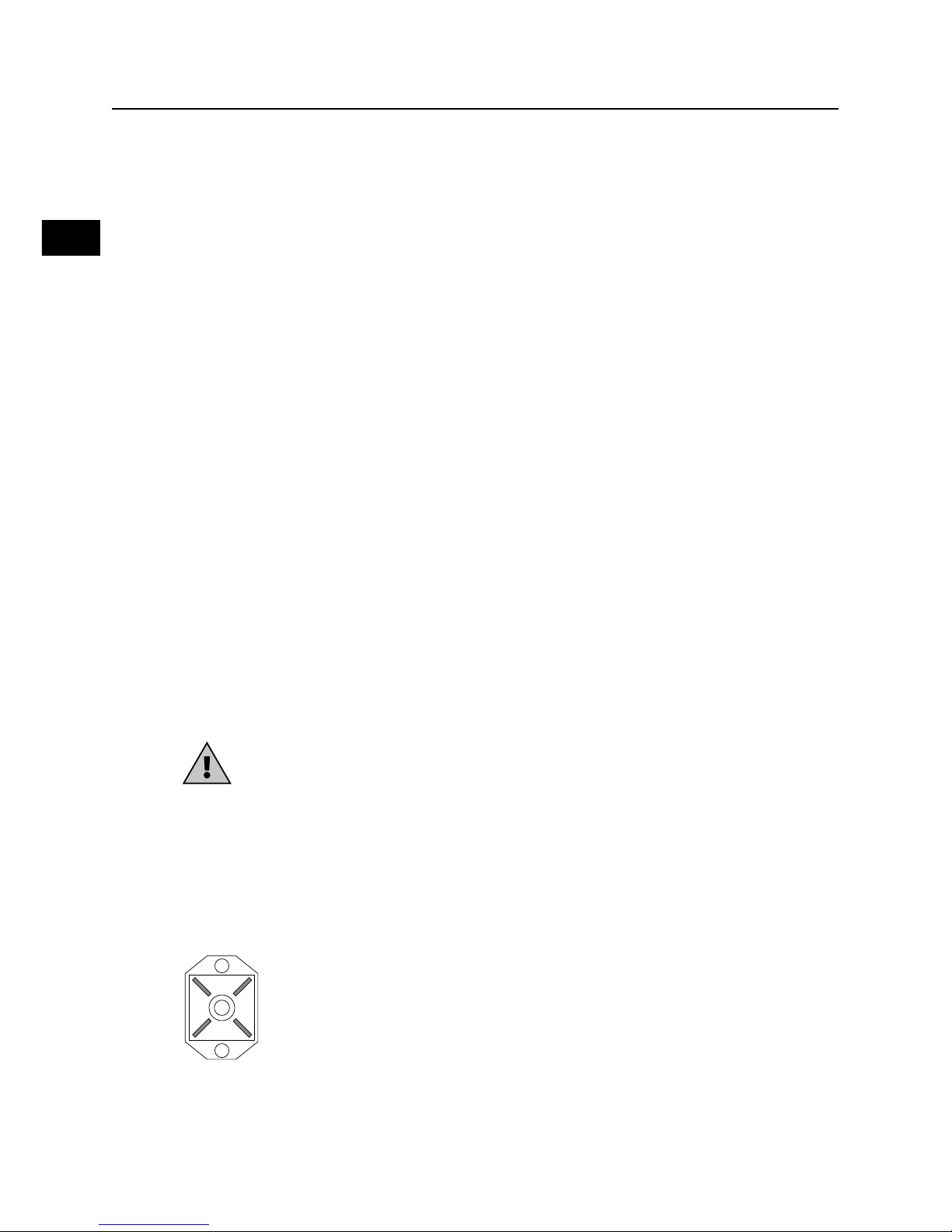
1. Unscrew the fixing nut of the connector located on the bottom right side of
the pump head and marked in the figure with an outgoing arrow.
2. Cut the white, semi-rigid polyethylene tube to the correct length.
3. Insert the fixing nut and the tube-wrench on the tube.
4. Mount the tube on the conic tube-holder of the suction connector,
pushing it firmly until it reaches the stop collar.
5. Fix the tube by screwing the fixing nut onto the head connector of the pump head.
6. Place the injection tube avoiding as much as possible the curves and ensuring
that the pulses do not make the tube rub against rigid bodies.
7. At the injection point on the pipeline, mount a ½” GAS
connection, internally threaded (not supplied).
8. Wrap Teflon tape to the thread and tighten the injection valve to the fitting.
9. Unscrew the pipe-wrench nut of the injection valve fitting.
10. Cut the white, semi-rigid, PE tube to the correct length.
11. Insert the pipe-wrench on the PE tube.
12. Mount the tube on the conic hose of the injection valve,
pushing it until it reaches the stop collar.
13. Screw the pipe-wrench nu tonto the valve fitting.
Note: The injection valve also works as non-return valve: do not dismantle.
ELECTRICAL CONNECTIONS
The BL530 unit is supplied already wired internally and complete with
power cable (without plug). This is the only electrical connection to be
performed by the customer. Standard power supply: 230 V, 50 Hz.
Carefully follow all the rules of electrical safety. Before starting the unit, check
that all electrical and plumbing connections have been properly executed.
The measure inputs from pH and redox electrodes are available on BNC connectors.
Note: the pH and redox inputs should never be left open; if an
input is not used, you need to short- circuit it.
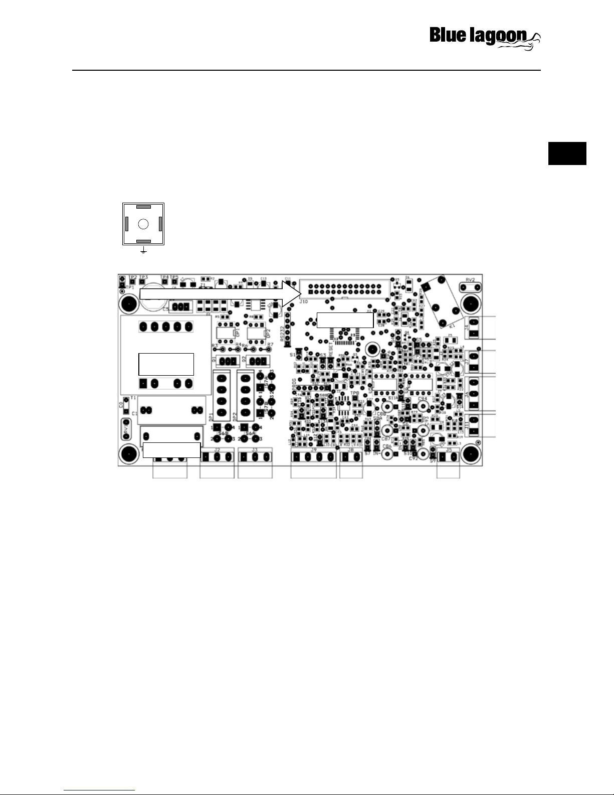
Level Control
The system is supplied already configured for disabling the dosage in case of low level in the tank.
The level control is made through a specific float sensor (optional, see “Accessories and spare
parts”), to be connected to pins 3 and 4 of the LEV connector (see Figure) When
the product level in the tank falls below the level sensor, the unit stops dosing
and the fault is shown on the display. The alarm condition is generated with a
delay of a few seconds compared to the detection of low level, to avoid errors
due to extreme situation (such as fluctuations in water). Two inputs for level
sensor are available, one for each pump / tank.
BL530 PH/RX DOSAGE SYSTEM
3
2
14

EN
BL530 PH/RX DOSAGE SYSTEM |9
UV-C and Pool equipment
Flow protection:
The system is supplied already configured for disabling the dosage in case of lack of water flow.
The control is made through a contact to be connected to pins 3 and of the FLOW connector
(see Figure). A specific flow switch is also available (optional, see “Accessories and spare parts”).
INTERNAL CONNECTIONS (for installers only)
The unit is provided pre-wired internally, and all connections of normal use
(power supply, measurement sensors and level sensors) are available externally via
cable or connector. However, if you need to operate on the electronic boards or
replace blown fuses, refer to the diagram below.
Notes:
• The possible reversal of the connections phase / zero of the
power supply does not affect the normal operation.
• If the level and flow inputs are not used, leave them open (not connected).
IN pH
IN RX
+ -
Level 1
+ -
Level 2
Br Bk Bl
Flow Reserved
OUT
Alarm
Y/G Br Br
Pump 1
Y/G Br Br
Pump 2
Reserved PT100Y/G N L
Power Supply
Power
Transformer
Processor
Fuse F1A
Connector for front board at cable
3
21

EN
10 | BL530 PH/RX DOSAGE SYSTEM
STARTUP
At start-up the microcontroller displays for a couple of seconds information about the firmware
(type / version), then shows the two measures flashing for all the start-up delay time (if set) and then
starts operating accordingly with the configured working mode.
DISPLAY
During normal operations, the display shows the two measured values on the top line, while the
bottom row displays the status of the two pumps. In models with Pt100 (optional) the bottom row
switches between the temperature measurement and the status of the two pumps.
For example:
• “7.25pH 286mV”.
• “P1 AAN P2 020%”.
• (pump 1 ON in ON/OFF mode, pump 2 ON in proportional mode with indication of the
functioning percentage).
In these conditions, pressing the orbutton, you can display the
OFFSET and GAIN values of the pH and redox measurements.
For example:
• "7.25pH".
• “O=-4 G=1.000”.
This information is useful to verify the electrode status. Note that an electrode in good condition
should have an offset close to zero and a gain close to 1.000. When these values deviate from the
ideal ones, indicate a dead electrode or sensor aging.
During manual working mode, the display shows on the top line the pump to
which the information refers, while the bottom row shows the pump status.
For example:
• “Pomp 2 manual””.
• “ON”.
In these conditions, pressing the ON/OFF button allows to enable / disable the pump.
In case of fault or alarm condition, the pump stops dosing until the normal working conditions are
restored.
BL530 PH/RX DOSAGE SYSTEM

EN
BL530 PH/RX DOSAGE SYSTEM |11
UV-C and Pool equipment
OPERATION OF THE ELECTRONIC UNIT
To access the configuration, calibration and manual mode menus, press the
CAL button. The display will show the following available options:
• Standard Conguration.
• Advanced Conguration.
• Calibration IN1 (input 1) pH.
• Calibration IN2 (input 2) redox.
• Manual Mode 1 (pump 1, acid dosage).
• Manual Mode 2 (pump 2, chlorine dosage).
Use the / keys to scroll the available options, then press CAL to enter the
highlighted mode or ESC to return to measurement visualization.
For a complete list of parameters, valid values and related explanations,
see the “List of Configuration Parameters” section.
Standard Conguration
The standard configuration mode allows the customer to set a series of parameters related to the
normal functioning of the unit. These parameter can be freely accessed and configured from the
front keyboard.
1. Once selected the “Standard Configuration" option, press the CAL button to edit the list of
parameters, or press ESC to return to the ESC to return to the normal visualization mode.
2. Now use the and keys to scroll the list of the available parameters.
3. To modify the displayed parameter, press CAL; to quit the mode press ESC.
Advanced Conguration
The advanced configuration mode also includes the parameters protected by password, that
allow a complete configuration of the system. This mode is normally accessed only by authorized
technical personnel.
1. Once selected the “Advanced Configuration” option, press the CAL button to edit the list of
parameters, or press ESC to return to the normal visualization mode.
2. Now use the and keys to scroll the list of the available parameters.
3. To modify the displayed parameter, press CAL; to quit the mode press ESC.
S T A N D A R D C O N F I G .
C A L > Y E S E S C > N O
P 0 1 F U N C . T Y P E P 1
O N O F F
A D V A N C E D C O N F I G .
C A L > Y E S E S C > N O

EN
12 | BL530 PH/RX DOSAGE SYSTEM
List of Conguration Parameters
In this section are listed all the configuration parameters. It is recommended
to fill the last column with the values set for your application.
PAR Description Min. Value Max. Value Default
Value
Set
Value
P01 Functioning Type Pump 1 ON-OFF / Proportional ON-OFF
P02 Setpoint Pump 1 0,00pH 14,00pH 7,00pH
P03 Hysteresis Pump 1 0,20pH 2,00pH 0,50pH
P04 Dosage Pump 1 Acidification / Alkalinisation Acidification
P05
Time Base Pump 1
if P01= ON-OFF
if P01= Proportional
5%
30 sec.
100%
360 sec.
60%
60 sec.
P06 Functioning Type Pump 2 ON-OFF / Proportional ON-OFF
P07 Setpoint Pump 2 0mV 1000mV 750mV
P08 Hysteresis Pump 2 20mV 200mV 50mV
P09 Dosage Pump 2 Chlorination / De-
chlorination Chlorination
P10
Time Base Pump 2
if P06= ON-OFF
if P06= Proportional
5%
30 sec.
100%
360 sec.
60%
60 sec.
P11 Alarm Pump 1 0 min. 240 min. 0 min.
P12 Alarm Pump 2 0 min. 240 min. 0 min.
P13 Start Delay 0 min. 60 min. 0 min.
P14 Language
Model
Italian,
French,
Model
Italian,
French,
BL530-1:
Dutch,
German
BL530-2:
English,
Spanish
Dutch
English
P15 Restore default values 0255 0
P16 Password 0255 0
P17 Alarm Functioning Relay NO / Relay NC Relay NO
P18 Flow Functioning Input NO / Input NC Input NO
P19 pH Equilibrium 0 min. 240 min. 0 min.
BL530 PH/RX DOSAGE SYSTEM

EN
BL530 PH/RX DOSAGE SYSTEM |13
UV-C and Pool equipment
Warning! The complete list of parameters can be accessed only from
the “Advanced Configuration” menu, while the “Standard Configuration”
mode allows to modify only the parameters that are not protected
by password (highlighted in bold in the table above).
PARAMETER 01 FUNCTIONING TYPE OF THE PUMP 1
This parameter allows to set the functioning type of pump 1, typically used for the pH control.
PARAMETER 02 SETPOINT PUMP 1
This parameter allows to enter the desired pH value for the swimming pool water. The dosing pump
is activated / de-activated to reach this value and keep it constant.
PARAMETER 03 HYSTERESIS PUMP 1
This parameter is sued to adjust the functioning hysteresis of pump 1 around the threshold set in
P02. It is recommended to set a narrow window in case of ON-OFF mode, while for proportional
mode it is advisable to set a window of at least points.
PARAMETER 04 DOSAGE DIRECTION OF PUMP 1
This parameter allows to set the dosage direction. The choice depends on the product dosed to
adjust the pH level: if you dose an acid, set this parameter to “Acidification”, while if you dose a base
set “Alkalinisation”.
PARAMETER 05 TIME BASE FOR PUMP 1
If the pump is configured to ON-OFF mode, this parameter indicates a percentage of operation of
the pump, on a fixed time base of 100 seconds. 100% corresponds to pump always ON, while 5%
indicates that the pump is ON for 5% of time (=5 seconds) and OFF for the remaining 96% (=95
seconds). If the pump is configured for proportional operation, this parameter indicates the time
base of pump.
PARAMETER 06 FUNCTIONING TYPE OF THE PUMP 2
This parameter allows to set the functioning type of pump 2, typically used for
controlling the redox potential level. See description of parameter P01.
PARAMETER 07 SETPOINT PUMP 2
See parameter P02, but referred to redox measurements.
PARAMETER 08 HYSTERESIS PUMP 2
See parameter P03, but referred to redox measurements.

EN
14 | BL530 PH/RX DOSAGE SYSTEM
PARAMETER 09 DOSAGE DIRECTION OF PUMP 2
See parameter P04, but referred to redox measurements and
dosing directions “Chlorination / De- chlorination”.
PARAMETER 10 TIME BASE FOR PUMP 2
See parameter P05, but referred to the pump 2.
PARAMETER 11 DOSAGE ALARM OF PUMP 1
This parameter allows to generate an alarm when the measurement does not return to the setpoint
value within a set time interval, from 0 (function disabled) to 240 minutes. The counter starts when
the unit detects a measurement that exceeds the setpoint value, and automatically resets to zero
when measurement returns to an acceptable. If measurement remains outside of the setpoint for
a time longer than that set, an alarm is generated, the display shows the message “Al.1” and the
pump stops dosing. To reset the alarm and resume to normal operations, press the ON/OFF button
or shutdown and restart the unit. This condition can occur when the dosage is insufficient to reach
the setpoint (P02).
PARAMETER 12 DOSAGE ALARM OF PUMP 2
See parameter P11, but referred to pump 2.
PARAMETER 13 STARTUP DELAY
This parameter allows to set a start-up delay, which is a time of waiting before starting
measurements to allow the correct polarization and stabilization of the measuring electrodes. This
prevents unreliable initial readings. Typically in the case of pH measurements one minute is enough,
while for redox electrodes may be necessary a delay of 30 minutes. This waiting time also allows to
compensate for any hydraulic delays which may occur at the start-up of the plant.
Set a time (in minutes) during which, after turning on the electronic unit, the system waits,
measurements blink on the display and the pumps are not active. After this time, the system begins
normal operation.
PARAMETER 14 LANGUAGE
This parameter allows to select the display language.
PARAMETER 15 RESTORE THE DEFAULT SETTINGS
This feature allows to restore the factory configuration if you want to delete
incorrect or undesired settings. Once confirmed this option, all custom
setting will be lost. To enable the feature, enter the value “12”.
BL530 PH/RX DOSAGE SYSTEM

EN
BL530 PH/RX DOSAGE SYSTEM |15
UV-C and Pool equipment
PARAMETER 16 PASSWORD
This parameter allows to enter a password (numeric value within 1 and 255) to protect the system
from unauthorized access. Once set and confirmed, the password will be requested to access the
menus “Advanced configuration” and “Manual mode”. The instrument is supplied with no password
set (P16=0). Warning! If you forget the password, you need to send back the unit to the factory for a
complete reconfiguration (out of warranty)!
PARAMETER 17 FUNCTIONING OF THE ALARM OUTPUT
This parameter allows to select the functioning mode of the alarm relay,
normally open “NO” (factory setting) or normally closed “NC”.
PARAMETER 18 FLOW FUNCTIONING
This parameter allows to select the functioning mode of the “flow” input,
normally open “NO” (factory setting) or normally closed “NC”.
Warning! The inversion of this parameter compared to the default setting can determine the
functioning of the device even in the absence of flow!
PARAMETER 19 PH EQUILIBRIUM
This parameter allows to set a maximum waiting time before activating the redox (chlorine)
adjustment, wenn the pH adjustment is active. This waiting time is counted from the start-
up of the equipment, simultaneously to a possible start-up delay set in P13, during which the
entire measuring system is in stand-by. In other words, the pH adjustment is activated after
the start-up delay (P13) has elapsed, while the redox (chlorine) regulation is activated when
the pH reaches the set threshold (P02) or in any case at the end of the “pH Equilibrium” period.
For example, if a 1-minute start-up delay is set and you want the pH is adjusted for a maximum
of 15 minutes before also activate the redox (chlorine) regulation, the “pH Equilibrium” time
should be set to 16 minutes. To disable this feature, simply set the parameter to 0 (default).
Notes:
• Once in configuration mode, if no button is pressed for 30 seconds,
the unit automatically returns to the idle mode.
• The system is factory configured with default values; you can delete undesired
settings and restore the initial configuration, using the “RESTORE” function (P15).

EN
16 | BL530 PH/RX DOSAGE SYSTEM
Electrochemical Calibration pH Calibration
1. Rinse the pH electrode with distilled water, then immerse it in the pH 7.01 pH buffer solution.
2. Press the CAL key to enter the menu mode and use the / keys
to select the option “IN1 CALIBRATION”.
3. Press CAL again to confirm.
4. Press to select the OFFSET calibration and confirm by pressing CAL.
5. The system automatically recognizes and displays the buffer value (7.01 pH).
6. If necessary, use the / keys to adjust the calibration value.
7. Press CAL to confirm the calibration, or ESC to quit the
procedure and keep the previous calibration.
8. Rinse the pH electrode with distilled water, then immerse
it in the pH 4.01 (or 9.01) buffer solution.
9. Press the CAL key to enter the menu mode and use the / keys
to select the option “IN1 CALIBRATION”.
10. Press CAL again to confirm.
11. Press to select the GAIN calibration and confirm by pressing CAL.
12. The system automatically recognizes and displays the buffer value (4.01 or 9.01 pH).
13. If necessary, use the / keys to adjust the calibration value.
14. Press CAL to confirm the calibration, or ESC to quit the
procedure and keep the previous calibration.
Notes
• If the system does not automatically recognize the buffers or the
“Calibration Impossible” error occurs, it can be due to:
a) Buffer solution contaminated or expired.
b) A faulty or defective electrode.
c) Connection cable or connector damaged.
• If you try to calibrate the offset at a pH value too different from 7.00, the calibration is
automatically ignored. Similarly if you try to calibrate the gain with a buffer solution at a pH too
BL530 PH/RX DOSAGE SYSTEM
I N 1 C A L I B R A T . P H
C A L > Y E S E S C > N O
I N 1 C A L I B R A T . P H
O F F S E T G A I N
I N 1 C A L I B R A T . P H
C A L > Y E S E S C > N O
I N 1 C A L I B R A T . P H
O F F S E T G A I N

EN
BL530 PH/RX DOSAGE SYSTEM |17
UV-C and Pool equipment
close to neutrality, the procedure will fail.
• During normal operation, it is possible to view the offset (pressing ) and gain (pressing )
values, to check the electrode status. The ideal values are an offset close to zero and a gain close
to 1.000. When these values are close to the max / min limits (offset: -1.00pH ... +1.00pH; gain:
0.750 ... 1.500), the electrode is contaminated or dead.
Redox Calibration
1. Rinse the electrode with distilled water, then immerse it in the calibration solution (e.g. 220 mV).
2. Press the CAL key to enter the menu mode and use the / keys
to select the option “IN2 CALIBRATION”.
3. Press CAL again to confirm.
4. Press to select the OFFSET calibration and confirm by pressing CAL.
5. The system automatically recognizes and displays the solution value (220 mV).
6. If necessary, use the / keys to adjust the calibration value.
7. Press CAL to confirm the calibration, or ESC to quit the
procedure and keep the previous calibration.
Notes
• If the system does not automatically recognize the buffers or
the “Calibration Impossible” error occurs, it can be due to:
a) Calibration solution contaminated or expired.
b) A faulty or defective electrode.
c) Connection cable or connector damaged.
• During normal operation, it is possible to view the offset value by pressing , to check
the electrode status. The ideal offset value is close to zero. When this value is close to
the max / min limits (-100mV ... +100mV), the electrode is contaminated or dead.
Manual Mode
At any time you can force a manual working mode, useful for a temporary
use of the system. If a password has been set (see parameter P16), the
system will require it to enable the access to this feature.
1. Press the CAL key to enter the menu mode and use the / keys to select the option
1. “MANUAL FUNC.1” (or “MANUAL FUNC.2”).
2. Press CAL again to confirm.
3. Similarly proceed for pump 2.
4. Press ESC at any time to exit the manual mode.
I N 2 C A L I B R A T . R X
O F F S E T
I N 2 C A L I B R A T . R X
C A L > Y E S E S C > N O

EN
18 | BL530 PH/RX DOSAGE SYSTEM
Warning! In manual mode only one pump at a time can be activated.
CONTROL EXAMPLES
Typical application in swimming pool control: acidification when pH exceeds the
pH value of 7.30. Refer to the “List of configuration parameters” and set:
• P01 ON/OFF working mode for pump 1.
• P02 set-point 7.30 pH.
• P04 dosage direction “ACIDIFICATION”.
• P11 alarm pump 1 = 60 minutes.
Typical application in swimming pool control: chlorination when redox potential
falls below 680 mV. Refer to the “List of configuration parameters” and set:
• P06 PROPORTIONAL working mode (recommended for an easier stabilisation).
• P07 set-point 680 mV.
• P09 dosage direction “CHLORINATION”.
• P10 if the quantity of the product to be injected is not known, it is recommended to start
with a time base of 60 seconds (default), and if the chlorination process would last too long,
decrease the time base gradually until a conditioning time of approx. 30-45 minutes.
• P12 alarm pump 2 = 60 minutes.
Common settings for the two examples described above:
• P13 start-up delay of 15 minutes (average time required
for the polarization of redox electrodes).
• P16 protection PASSWORD to prevent unauthorized access.
ERRORS / ALARMS
Every error or anomaly detected by the system generates an alarm message on the display:
LEV1 / LEV2 The level sensor 1 or 2 detected a low level of the liquid
to be dosed; restore the level into the related tank.
FLOW The flow sensor detected an anomaly that can be due to low
pressure into the hydraulic circuit or wrong adjustment of the flow
sensor in the electrode-holder; restore the flow or adjust the sensor.
STOP This message indicates that the pumps have been manually
de- activated by pressing the ON/OFF button.
UR / OR Under/Over Range: measurement out of range; this signal
BL530 PH/RX DOSAGE SYSTEM
M A N U A L F U N C . P 1
C A L > Y E S E S C > N O
M A N U A L P U M P 1
O F F

EN
BL530 PH/RX DOSAGE SYSTEM |19
UV-C and Pool equipment
can be generated by a dead or broken electrode, or by
a damaged or disconnected cable; check the system
and restore correct measurement conditions.
AL.1 / AL.2 Dosing time alarm for pump 1 or 2: measurement is outside
the set-point for a time longer than the set limit, due to an
insufficient dosage or a wrong configuration of the alarm time
(see parameters P11 and P12); set the parameters properly.
Calibration impossible Check the status of electrode and connection cable;
check that the calibration solutions are not expired
or contaminated; repeat the procedure.
MAINTENANCE
The periodic maintenance operations are essential for the proper functioning of the
system and its duration in time. The below advices should be strictly followed.
Before any operation, make sure the system is unplugged!
Dosing Pumps
Weekly operations:
• Check the level of the solution to be dosed to prevent the pump from running dry.
• Check that the suction and head pipes are clean and not containing any impurities.
• Check that the filter is not clogged to avoid the decreasing of flow rate.
Operations every three months (or in case of pump drifting):
RClean all the parts that come into contact with the chemical (pump body, foot filter and
injection valve). If the pump doses additives that from crystals, clean more frequently.
Proceed as follows:
• Dip the suction tube and the foot filer into clean water.
• Start the pump and leave it run for a few minutes to let the water wash the pump head.
If there are crystals to remove, proceed as follows:
• First use a proper chemical (instead of water) to dissolve the
crystals and let the pump work for a few minutes.
• Repeat the procedure with clean water.
Once the cleaning is done, connect again the pump to the plant and resume normal operations.

EN
20 | BL530 PH/RX DOSAGE SYSTEM
BL530 PH/RX DOSAGE SYSTEM
Extraordinary maintenance – Replacing the peristaltic tube:
Pump wintering:
Before shutting down the system for wintering or anyway for a
long period, dose clean water to rinse the tube, then rotate the
roller-holder clockwise to position it as shown in the figure.
pH and Redox Electrodes
Typically, it is recommended to clean the electrodes when the response is slow or
measurements are not reliable, and when they have been used for a long time, especially
in aggressive solutions, pollutants, very acidic or very alkaline environments.
A kit of solutions is available, for the cleaning and storage of pH and redox electrodes.
The kit includes three solutions:
• Solution A: dip the electrode in this solution for cleaning it.
• Solution B: use this solution to rinse the electrode, before and after cleaning.
• Solution C: storage solution to be used for filling the electrode protective
cap when the electrode is not used (wintering, closure of the plant).
Unscrew the two front screws and remove the transparent cover.
To remove the old tube, first release the left connector
and then turn the roller-holder as shown by the arrow in
the figure, to free the tube up to the right connector.
Insert the left connector into the new tube, in its housing, while
making sure that the rounded part is positioned inward. Then turn
the roller-holder clockwise, so that the tube is inserted in its housing
Insert the right connector in its housing and tighten the two front
screws to fix the transparent cover
Table of contents
Languages:
Other VGE Lighting Equipment manuals
Popular Lighting Equipment manuals by other brands

wesmartify
wesmartify essentials Smart Home LED Light Chain RGBW... user manual

Acuity Brands
Acuity Brands HEALTHCARE LIGHTING RK1HPL manual

OSA Opto Light
OSA Opto Light OLM-056 manual

Pinegreen Lighting
Pinegreen Lighting CL-WLS7000-3CCT installation instructions

Kelvix
Kelvix SLINX installation instructions

Lupo
Lupo Ultrapanel Dual Color 30 Soft manual