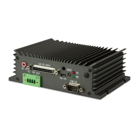
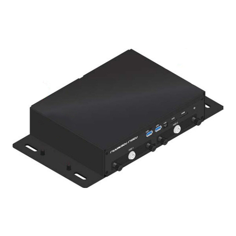
VIA Technologies Mobile360 M820 User manual

USER MANUAL
VIA Mobile360 M820
Fanless ultra-compact in-vehicle
safety system with exible ADAS,
SVS, and DMS integraon opons
1.01-28042021

Copyright
Copyright © 2020 VIA Technologies Incorporated. All rights reserved.
No part of this document may be reproduced, transmied, transcribed, stored in a retrieval system, or translated into any language, in any
form or by any means, electronic, mechanical, magnec, opcal, chemical, manual or otherwise without the prior wrien permission of
VIA Technologies, Incorporated.
Trademarks
All trademarks are the property of their respecve holders.
Disclaimer
No license is granted, implied or otherwise, under any patent or patent rights of VIA Technologies. VIA Technologies makes no warranes,
implied or otherwise, in regard to this document and to the products described in this document. The informaon provided in this
document is believed to be accurate and reliable as of the publicaon date of this document. However, VIA Technologies assumes no
responsibility for the use or misuse of the informaon (including use or connecon of extra device/equipment/add-on card) in this
document and for any patent infringements that may arise from the use of this document. The informaon and product specicaons
within this document are subject to change at any me, without noce and without obligaon to nofy any person of such change.
VIA Technologies, Inc. reserves the right the make changes to the products described in this manual at any me without prior noce.
Regulatory Compliance
FCC-A Radio Frequency Interference Statement
This equipment has been tested and found to comply with the limits for a class A digital device, pursuant to part 15 of the FCC rules.
These limits are designed to provide reasonable protecon against harmful interference when the equipment is operated in a commercial
environment. This equipment generates, uses, and can radiate radio frequency energy and, if not installed and used in accordance with the
instrucon manual, may cause harmful interference to radio communicaons. Operaon of this equipment in a residenal area is likely to
cause harmful interference, in which case the user will be required to correct the interference at his personal expense.
Noce 1
The changes or modicaons not expressly approved by the party responsible for compliance could void the user's authority to operate
the equipment.
Noce 2
Shielded interface cables and A.C. power cord, if any, must be used in order to comply with the emission limits.
Noce 3
The product described in this document is designed for general use, VIA Technologies assumes no responsibility for the conicts or
damages arising from incompability of the product. Check compability issue with your local sales representaves before placing an
order.
ii

Baery Recycling and Disposal
• Only use the appropriate baery specied for this product.
• Do not re-use, recharge, or reheat an old baery.
• Do not aempt to force open the baery.
• Do not discard used baeries with regular trash.
• Discard used baeries according to local regulaons.
Safety Precauons
• Always read the safety instrucons carefully.
• Keep this User’s Manual for future reference.
• All cauons and warnings on the equipment should be noted.
• Keep this equipment away from humidity.
• Put this equipment on a reliable at surface before seng it up.
• Check the voltage of the power source and adjust to 110/220V before connecng the equipment to
the power inlet.
• Do not place the power cord where people will step on it.
• Always unplug the power cord before inserng any add-on card or module.
• If any of the following situaons arise, get the equipment checked by authorized service personnel:
− The power cord or plug is damaged.
− Liquid has entered into the equipment.
− The equipment has been exposed to moisture.
− The equipment is faulty or you cannot get it work according to User’s Manual.
− The equipment has been dropped and damaged.
− The equipment has an obvious sign of breakage.
• Do not leave this equipment in extreme temperatures or in a storage temperature above 70°C (158°F).
The equipment may be damaged.
• Do not leave this equipment in direct sunlight.
• Never pour any liquid into the opening. Liquid can cause damage or electrical shock.
• Do not place anything over the power cord.
• Do not cover the venlaon holes. The openings on the enclosure protect the equipment from
overheang.
iii

VIA Mobile360 M820 User Manual
iv
Box Contents
• VIA Moblie360 M820 system
• Phoenix plug to DC jack
• COM cable (for debugging)
• GPS antenna
• 2 x Wi-Fi/BT antennas
Ordering Informaon
Part Number Descripon
M360-820-1Q20A1 Fanless mobile system with 2.054GHz Qualcomm® APQ8096A Embedded
Processor, 4GB LPDDR4 SDRAM, HDMI, 2 USB 3.0, Micro USB 2.0 (debugging),
DIO, COM, CAN bus, Gigabit Ethernet, 9 FAKRA connectors for camera-in, Wi-Fi,
Bluetooth 4.1, GPS, SIM card slot, Micro SD card slot, 2 M.2 slots, 2 2.5" SSD/HDD
bays ,12V DC-out, 9~36V DC-in with IGN
Oponal Accessories
Camera and Accessories
Part Number Descripon
M360-ADAS-1C19A1 1.0MP FOV-35 720p CMOS Front ADAS camera with microphone, speaker and
mounting bracket
M360-DMS-1C19A1 1.0MP FOV-60 720p CMOS DMS camera with IR and mounting bracket
99G40-08115Z 1.0MP FOV-35 720p CMOS automotive-grade camera for BSD
99G40-08116Z 1.0MP FOV-190 720p CMOS automotive-grade camera for SVS + Rear ADAS
99G33-230406 15M FAKRA cable
M360-CBKT-00A1 Camera mounting braket for SVS/BSD 42mm x 28.2mm x 32.3mm (1.65" x 1.11"
x 1.27")
Display Accessories
Part Number Descripon
99G73-01034C 10" Resisve touch monitor (1280x800)
99G73-01030C 7" Resisve touch monitor (1280x800)
Storage Opons
Part Number Descripon
99G61-080554 512GB Transcend 2.5" MLC SSD (-40°C~90°C)
99G61-080904 128GB Transcend 2.5" MLC SSD (-40°C~90°C)
Wireless Modules
Part Number Descripon
99G40-071467 4G LTE/DC-HSPA+/EGPRS Mobile broadband full-size miniPCIe module
(For North America Regions)
99G40-071967 4G LTE/DC-HSPA+/EGPRS Mobile broadband full-size miniPCIe module
(For APAC+ South America Regions)
99G40-071457 4G LTE/DC-HSPA+/EGPRS Mobile broadband full-size miniPCIe module
(For EU/APAC Regions)

VIA Mobile360 M820 User Manual
v
Mounng Opons
Part Number Descripon
M360-SBKT-00A1 Mounng bracket, 337.2mm x 185mm x 62mm

VIA Mobile360 M820 User Manual
vi
Table of Contents
1. Product Overview........................................................................................................................................... 1
1.1 Key Features ......................................................................................................................................... 1
1.1.1 High-Performance.......................................................................................................................... 1
1.1.2 Fanless, Compact, Ruggedized Chassis .......................................................................................... 1
1.1.3 Opmized Integraon with Mulple I/O Access............................................................................ 1
1.1.4 Mulple Camera Support .............................................................................................................. 1
1.1.5 Support for a Wide Range of Power Sources................................................................................. 1
1.1.6 Storage Expansion.......................................................................................................................... 2
1.1.7 Networking Support ...................................................................................................................... 2
1.1.8 Mounng Soluon ......................................................................................................................... 2
1.1.9 Embedded Operang System Ready.............................................................................................. 2
1.2 Product Specicaons ......................................................................................................................... 2
1.3 Layout Diagram..................................................................................................................................... 4
2. External I/O Pin Descripons and Funconality............................................................................................. 7
2.1 HDMI®Port............................................................................................................................................ 7
2.2 USB 3.0 Ports ........................................................................................................................................ 7
2.3 Micro USB 2.0 Port ............................................................................................................................... 7
2.4 Gigabit Ethernet Port............................................................................................................................ 8
2.5 Micro SD Card Slot................................................................................................................................ 8
2.6 SIM Card Slot ........................................................................................................................................ 9
2.7 DIO Port .............................................................................................................................................. 10
2.8 Headphone and Mic-in Port ............................................................................................................... 10
2.9 COM Port ............................................................................................................................................ 10
2.10 CAN Bus Port ...................................................................................................................................... 11
2.11 FAKRA Connectors .............................................................................................................................. 11
2.12 Power Buon...................................................................................................................................... 11
2.13 DC-in Jack ........................................................................................................................................... 12
2.14 DC-out Jack......................................................................................................................................... 12
2.15 Antenna Connectors........................................................................................................................... 13
3. Onboard I/O ................................................................................................................................................ 14
3.1 MiniPCIe Slot ...................................................................................................................................... 14
4. Hardware Installaon ................................................................................................................................... 15
4.1 Installing the 2.5" SATA HDD/SSD ....................................................................................................... 15
4.2 Installing the Wi-Fi Antennas.............................................................................................................. 17
4.3 Installing the GPS Antenna ................................................................................................................. 17
4.4 Installing the FOV Cameras and FAKRA Cables ................................................................................... 18
4.5 Unplugging the FAKRA Cable.............................................................................................................. 19
4.6 Connecng the VIA Mobile360 M820 to the Vehicle's Ignion (IGN) ................................................ 20
4.7 Installing the Phoenix Plug to DC Jack ................................................................................................ 21
5. Soware and Technical Support................................................................................................................... 22
5.1 Yocto Support ..................................................................................................................................... 22
5.2 Technical Support and Assistance....................................................................................................... 22

VIA Mobile360 M820 User Manual
vii
Table of Contents
Appendix A Installing Wireless Accessories ..................................................................................................... 23
A.1 Installing the Mobile Broadband MiniPCIe Module ........................................................................... 23
Appendix B Installing Automove-Grade Cameras to the Camera Brackets.................................................... 26
B.1 Installing the FOV-190 Automove-Grade Camera to the Camera Bracket........................................ 26
B.2 Installing the FOV-35 Automove-Grade Camera to the Camera Bracket.......................................... 29
B.3 Installing the Front ADAS Automove-Grade Camera........................................................................ 33
B.4 Installing the DMS Automove-Grade Camera .................................................................................. 37
Appendix C Installing Mounng Bracket.......................................................................................................... 40

VIA Mobile360 M820 User Manual
viii
List of Figures
Figure 01: Front panel I/O layout ......................................................................................................................... 4
Figure 02: Back panel I/O layout .......................................................................................................................... 5
Figure 03: Dimensions of the VIA Mobile360 M820 (front view)......................................................................... 5
Figure 04: Dimensions of the VIA Mobile360 M820 (side view) .......................................................................... 5
Figure 05: Dimensions of the VIA Mobile360 M820 (boom view)..................................................................... 6
Figure 06: HDMI port diagram ............................................................................................................................. 7
Figure 07: USB 3.0 port diagram .......................................................................................................................... 7
Figure 08: Micro USB 2.0 port diagram ............................................................................................................... 8
Figure 09: Gigabit Ethernet port diagram ............................................................................................................ 8
Figure 10: Micro SD card slot diagram ................................................................................................................ 9
Figure 11: SIM card slot diagram.......................................................................................................................... 9
Figure 12: DIO port diagram............................................................................................................................... 10
Figure 13: Headphone and Mic-in port diagram................................................................................................ 10
Figure 14: COM port diagram............................................................................................................................. 10
Figure 15: CAN bus port diagram ....................................................................................................................... 11
Figure 16: FAKRA connector diagram................................................................................................................. 11
Figure 17: Power buon diagram....................................................................................................................... 11
Figure 18: DC-in jack diagram............................................................................................................................. 12
Figure 19: DC-out jack diagram .......................................................................................................................... 12
Figure 20: Wi-Fi antenna connectors diagram ................................................................................................... 13
Figure 21: GPS and 4G antenna connectors diagram ......................................................................................... 13
Figure 22: MiniPCIe slot diagram ....................................................................................................................... 14
Figure 23: Unlocking the SATA HDD/SSD bay .................................................................................................... 15
Figure 24: Removing the SATA HDD/SSD bays.................................................................................................... 15
Figure 25: Installing the 2.5" SATA HDD/SSD ..................................................................................................... 16
Figure 26: Reinstalling the SATA HDD/SSD bays ................................................................................................. 16
Figure 27: Installing the Wi-Fi antennas............................................................................................................. 17
Figure 28: Installing the GPS antenna ................................................................................................................ 17
Figure 29: Connecng the FOV camera to the FAKRA cable............................................................................... 18
Figure 30: Connecng the FAKRA cable to the FAKRA connector ...................................................................... 18
Figure 31: Unplugging the FAKRA cable ............................................................................................................. 19
Figure 32: DIO port's pin 8 ................................................................................................................................. 20
Figure 33: VIA Mobile360 M820 and IGN connecon method diagram ............................................................ 20
Figure 34: Connecng the baery cables onto the Phoenix plug to DC jack ..................................................... 21
Figure 35: Connecng the Phoenix plug to DC jack............................................................................................ 21
Figure 36: Unscrewing the boom plate cover .................................................................................................. 23
Figure 37: Removing the boom plate cover..................................................................................................... 24
Figure 38: Installing the mobile broadband module .......................................................................................... 24
Figure 39: Connecng the 4G antenna cable to the micro-RF connector on the module.................................. 25
Figure 40: Installing the 4G antenna .................................................................................................................. 25
Figure 41: Aaching the internal bracket to the external bracket...................................................................... 26
Figure 42: Installing the double-sided adhesive tape on the camera bracket.................................................... 26
Figure 43: Installing the FOV-190 camera on the camera bracket...................................................................... 27
Figure 44: Removing the double-sided adhesive tape protecve cover ............................................................ 27

VIA Mobile360 M820 User Manual
ix
List of Figures
Figure 45: Installing the camera bracket with FOV-190 camera on your vehicle ............................................... 28
Figure 46: Adjusng the FOV-190 camera angle ................................................................................................ 28
Figure 47: Aaching the internal bracket to the external bracket...................................................................... 29
Figure 48: Installing the double-sided adhesive tape on the camera bracket.................................................... 29
Figure 49: Preparing the FOV-35 camera ........................................................................................................... 30
Figure 50: Installing the FOV-35 camera on the camera bracket........................................................................ 30
Figure 51: Removing the double-sided adhesive tape protecve cover ............................................................ 31
Figure 52: Installing the camera bracket with FOV-35 camera on your vehicle ................................................. 32
Figure 53: Adjusng the FOV-35 camera angle .................................................................................................. 33
Figure 54: Removing the protecve lens cover .................................................................................................. 34
Figure 55: Installing the Front ADAS camera...................................................................................................... 34
Figure 56: Adjusng the Front ADAS camera angle............................................................................................ 35
Figure 57: Connecng the power and microphone/speaker adapter cable....................................................... 35
Figure 58: Connecng the 2-pole power connector for the Front ADAS camera............................................... 36
Figure 59: Connecng the HP/MIC/GND wires for the Front ADAS camera....................................................... 36
Figure 60: Removing the double-sided adhesive tape protecve cover ............................................................ 37
Figure 61: Installing the DMS camera in your vehicle ........................................................................................ 38
Figure 62: Adjusng the DMS camera angle ...................................................................................................... 38
Figure 63: Connecng the USB power adapter cable......................................................................................... 39
Figure 64: Connecng the USB cable to the VIA Mobile360 M820.................................................................... 39
Figure 65: Mounng bracket parts..................................................................................................................... 40
Figure 66: Installing the VIA Mobile360 M820 onto the top casing................................................................... 40
Figure 67: Installing the base cover.................................................................................................................... 41
Figure 68: Securing the top casing and base cover together ............................................................................. 41
Figure 69: Mounng the VIA Mobile360 M820 ................................................................................................. 42

VIA Mobile360 M820 User Manual
x
List of Tables
Table 01: HDMI port pinouts .............................................................................................................................. 7
Table 02: USB 3.0 port pinouts ........................................................................................................................... 7
Table 03: Micro SD card slot pinouts .................................................................................................................. 8
Table 04: Gigabit Ethernet port pinouts ............................................................................................................. 8
Table 05: Gigabit Ethernet port LED color denion .......................................................................................... 8
Table 06: SIM card slot pinouts........................................................................................................................... 9
Table 07: SIM card slot pinouts........................................................................................................................... 9
Table 08: DIO port pinouts................................................................................................................................ 10
Table 09: Headphone and Mic-in port pinouts................................................................................................. 10
Table 10: COM port pinouts.............................................................................................................................. 10
Table 11: CAN bus ports pinouts....................................................................................................................... 11
Table 12: FAKRA connector pinout ................................................................................................................... 11
Table 13: Power buon behavior descripon................................................................................................... 12
Table 14: Power buon behavior descripon................................................................................................... 12
Table 15: DC-out jack pinouts........................................................................................................................... 12
Table 16: MiniPCIe slot pinouts ........................................................................................................................ 14

VIA Mobile360 M820 User Manual
1
1. Product Overview
The VIA Mobile360 M820 is a fanless ultra-compact in-vehicle 360° surround view surveillance and ADAS
system. It delivers real-me in-vehicle 360° video monitoring and recording for up to nine automove-grade
camera streams, and boost vehicle safety and eciency with ADAS technology.
With its ruggedized design that has been opmized for the most demanding on-road and o-road condions,
the VIA Mobile360 M820 provides a exible and high-performance soluon for a wide variety of applicaons
ranging from Freight Transportaon & Delivery, Construcon, Industrial, & Mining, and Agriculture & Forestry
to Refuse Collecon, Armored Cars & Secure Freight Shipping, and Buses and Coaches.
The VIA Mobile360 M820 is powered by the Qualcomm® APQ8096A Embedded Processor, which features
two high-performance Kryo™ cores up to 2.054GHz two low-power Kryo cores up to 1.593GHz. It combines
advanced compung, graphics and AI processing performance, rich connecvity opons, and I/O peripheral
integraon capabilies in an ultra-compact fanless system.
Measuring just 240mm (W) x 53mm (H) x 180mm (D), the system integrates a rich set of I/O features through
the front and back panels of its ultra-compact chassis, including an HDMI port, two USB 3.0 ports, Gigabit
Ethernet, CAN bus, nine FAKRA connectors for camera-in, and a Micro SD card slot. Other features include 4GB
LPDDR4 SDRAM, 16GB eMMC ash memory, a SIM card slot, DIO, COM, and a headphone & mic-in port.
The VIA Mobile360 M820 supports high compung power operaon with low power consumpon, and it has a
built-in power management system that protects from power surges – guarding against damage from transient
car power. With the power management system, it is capable of handling a wide range of DC power inputs
from 9~36V.
1.1 Key Features
1.1.1 High-Performance
The VIA Mobile360 M820 system is powered by a Qualcomm® APQ8096A Embedded Processor that provides a
full range of rich features including superb mul-tasking performance that delivers consistent performance for
a host of connected device applicaons.
1.1.2 Fanless, Compact, Ruggedized Chassis
The VIA Mobile360 M820 delivers fanless operaon in a sealed aluminum alloy chassis that also acts as a
thermal soluon. The compact chassis design makes it suitable for installaons in space-crical environments,
while also ensuring maximum reliability.
1.1.3 Opmized Integraon with Mulple I/O Access
With front and back panel I/O access, the VIA Mobile360 M820 can be easily congured to support a wide
variety of applicaons with easy integraon and quick setup.
1.1.4 Mulple Camera Support
The VIA Mobile360 M820 is equipped with nine FAKRA connectors for camera-in, making it ideal for in-vehicle
360° SVS, DMS, and ADAS applicaons.
1.1.5 Support for a Wide Range of Power Sources
The VIA Mobile360 M820 supports a wide range of input power, from 9V to 36V DC. Flexible power input
enables the VIA Mobile360 M820 to be deployable in a broad variety of automaon environments.

VIA Mobile360 M820 User Manual
2
1.1.6 Storage Expansion
The VIA Mobile360 M820 has 16GB of eMMC ash storage onboard, and features a Micro SD card slot
supporng an addional 32GB, and two HDD/SSD bays for 2.5" SATA HDD/SSD.
1.1.7 Networking Support
The VIA Mobile360 M820 is equipped with Wi-Fi, GPS, and an RJ-45 port that provides high-speed Gigabit
Ethernet. The 4G connecvity can be added through the miniPCIe slot using the oponal mobile broadband
miniPCIe module.
1.1.8 Mounng Soluon
The VIA Mobile360 M820 supports mulple methods for secure chassis mounng. The rugged VIA Mobile360
M820 can be mounted on the side-panel of a vehicle, oor bed, or any at surface.
1.1.9 Embedded Operang System Ready
The VIA Mobile360 M820 features a complete soware evaluaon image based on Yocto 2.3.
1.2 Product Specicaons
Processor
• Qualcomm® APQ8096A Embedded Processor
−Two high-performance Kryo cores up to 2.054GHz
−Two low power Kryo cores up to 1.593GHz
System Memory
• 4GB LPDDR4 SDRAM
Storage
• 16GB eMMC ash memory
• 2 x M.2 SATA slots
• 2 x 2.5" SATA HDD/SSD storage bays
Graphics
• Qualcomm® Adreno™ 530 GPU
−3D graphics accelerator with 64-bit addressing 624MHz
−Graphics engine supporng OpenGL ES 3.1/GEP, GL4.4, DX11.3/4, OpenCL 2.0, Renderscript-Next
−Supports H.264, VP8, HEVC 8/10-bit, VP9 video decoding up to: 4K@60fps, 1080p@240fps, 8 x
1080p@30fps
Camera-in Interface
• 3 x DS90UB964-Q1 Quad FPD-Link III deserializer Hub
LAN
• RTL8111G Ethernet Controller
Wireless Connecvity
• AMPAK AP12356_I MiniPCIe Wi-Fi/BT 4.1 module
• MAX-M8Q-0-10 u-blox 8 GNSS module

VIA Mobile360 M820 User Manual
3
Audio
• TI 6PAIC3104IRHBRQ1 Audio Codec
HDMI
• Integrated HDMI 2.0 transmier
Expansion I/O
• 1 x MiniPCIe slot (USB only) for 4G module
• 1 x MiniPCIe slot (PCIe/USB) for Wi-Fi/BT module
Front Panel I/O
• 2 x USB 3.0 ports
• 1 x Micro USB 2.0 port (for debugging)
• 1 x Micro SD card slot
• 1 x SIM card slot
• 2 x 2.5" SATA HDD/SSD bays
• 1 x Power buon
Back Panel I/O
• 1 x HDMI port
• 1 x DIO port
• 1 x COM port
• 1 x CAN bus port
• 1 x Gigabit Ethernet port
• 9 x FAKRA connectors for camera-in
• 1 x Headphone and Mic-in port
• 4 x Antenna connectors for Wi-Fi, 4G, GPS
• 1 x 4-pole Phoenix 9~36 V DC-in
• 1 x 2-pole Phoenix 12V DC-out
Power Supply
• 9~36V DC-in with IGN
Operang System
• Yocto 2.3
Operang Temperature
• -20°C ~ 70°C
Storage Temperature
• -20°C ~ 70°C
Operang Humidity
• 0 ~ 95% (non-condensing)
Vibraon Loading During Operaon
• ISO-16750-3 Test VII compliance
Shock During Operaon
• ISO-16750-3 Test VII compliance

VIA Mobile360 M820 User Manual
4
Mechanical Construcon
• Aluminum alloy top cover
• Metal chassis housing
Dimensions
• 240mm (W) x 53mm (H) x 180mm (D) (9.45" x 2.09" x 7.09")
Weight
• 3.0kg (6.61lbs)
Compliance
• CE, FCC
Notes:
1. As the operang temperature provided in the specicaons is a result of tesng performed in a tesng chamber, a
number of variables can inuence this result. Please note that the working temperature may vary depending on
the actual situaon and environment. It is highly recommended to execute a solid tesng program and take all
variables into consideraon when building the system. Please ensure that the system is stable under at the
required operang temperature in terms of applicaon.
2. Please note that the lifespan of the onboard eMMC/UFS memory chip may vary depending on the amount of
access. More frequent and larger data access on the eMMC memory will shorten lifespan. Therefore, it is highly
recommended to use replaceable external storage (e.g., SD card) for large data access.
1.3 Layout Diagram
Figure 01: Front panel I/O layout

VIA Mobile360 M820 User Manual
5
Figure 02: Back panel I/O layout
Figure 03: Dimensions of the VIA Mobile360 M820 (front view)
Figure 04: Dimensions of the VIA Mobile360 M820 (side view)

VIA Mobile360 M820 User Manual
6
Figure 05: Dimensions of the VIA Mobile360 M820 (boom view)

VIA Mobile360 M820 User Manual
7
2. External I/O Pin Descripons and Funconality
The VIA Mobile360 M820 has a wide selecon of interfaces, and includes a selecon of frequently-used ports
as part of the external I/O coastline.
2.1 HDMI®Port
The VIA Mobile360 M820 is equipped with one HDMI port on the back panel. A HDMI port Type A receptacle
connector provides connecon to High Denion video and digital audio using a single cable. The pinouts of
the HDMI port are shown below.
Pin Signal Pin Signal
1D2+ 11 GND
2GND 12 CLK-
3D2- 13 CEC
4D1+ 14 NC
5 GND 15 DDC_CLK
6D1- 16 DDC_DATA
7 D0+ 17 GND
8GND 18 HDMI_5V
9 D0- 19 PLUG_DET
10 CLK+
Figure 06: HDMI port diagram
Table 01: HDMI port pinouts
2.2 USB 3.0 Ports
The VIA Mobile360 M820 is equipped with two USB 3.0 ports on the front panel. Each USB 3.0 port has a
maximum data transfer rate of up to 5Gbps and is backwards compable with the USB 2.0 specicaon. The
USB ports provides complete Plug and Play and hot swap capabilies for external devices. The pinouts of the
USB 3.0 ports are shown below.
Pin Signal
1 VBUS
2D-
3D+
4GND
5RX-
6RX+
7 GND
8TX-
9 TX+
Figure 07: USB 3.0 port diagram
Table 02: USB 3.0 port pinouts
2.3 Micro USB 2.0 Port

VIA Mobile360 M820 User Manual
8
The VIA Mobile360 M820 is equipped with one Micro USB 2.0 port located on the front panel. The Micro USB
2.0 port supports OTG (On-The-Go) for debugging. The pinouts of the Micro USB 2.0 port are shown below.
Pin Signal
1 VBUS
2D-
3D+
4ID
5 GND
Figure 08: Micro USB 2.0 port diagram
Table 03: Micro SD card slot pinouts
2.4 Gigabit Ethernet Port
The VIA Mobile360 M820 comes with one Gigabit Ethernet port on the back panel which uses an 8 Posion
and 8 Contact (8P8C) receptacle connector commonly known as RJ-45. It is fully compliant with the IEEE 802.3
(10BASE-T), 802.3u (100BASE-TX), and 802.3ab (1000BASE-T) standards. The pinouts of the Gigabit Ethernet
port are shown below.
Pin Signal
1TX1+
2TX1-
3TX2+
4TX2-
5 TX3+
6TX3-
7 TX4+
8TX4- Figure 09: Gigabit Ethernet port diagram
Table 04: Gigabit Ethernet port pinouts
The Gigabit Ethernet port (RJ-45) is equipped with two LED indicators on the front side to show its Acve/Link
status and Speed status.
Acve LED
(Le LED on RJ-45 port)
Link LED
(Right LED on RJ-45 port)
Link o LED is o LED is o
Speed_10Mbit Green ash LED is o
Speed_100Mbit Red ash LED is o
Speed_1000Mbit LED is o Orange ash
Table 05: Gigabit Ethernet port LED color denion
2.5 Micro SD Card Slot

VIA Mobile360 M820 User Manual
9
The VIA Mobile360 M820 comes with a Micro SD card slot located on the front panel with support for a
maximum storage capacity of 32GB. The pinouts of the Micro SD card slot are shown below.
Pin Signal
1SD_DAT2
2SD_DAT3
3SD_CMD
4VDD
5 SD_CLK
6GND
7 SD_DAT0
8SD_DAT1
9 SD_CD-
Figure 10: Micro SD card slot diagram
Table 06: SIM card slot pinouts
2.6 SIM Card Slot
The VIA Mobile360 M820 comes with an oponal SIM card slot located on the front panel that supports 4G
SIM cards. SIM card usage on the VIA Mobile360 M820 requires that a 4G module is installed in the miniPCIe
slot, enabling the 4G funconality, otherwise the SIM card slot will be disabled. The SIM card slot is designed
for use with 4G modules that do not support built-in SIM card slots. The pinouts of the SIM card slot are shown
below.
Pin Signal
1VSIM_VCC
2GND
3VSIM_RST
4VSIM_VCC
5 VSIM_CLK
6VSIM_DATA
7 GND
8 NC
Figure 11: SIM card slot diagram
Table 07: SIM card slot pinouts

VIA Mobile360 M820 User Manual
10
2.7 DIO Port
The VIA Mobile360 M820 is equipped with a DIO port located on the back panel. The DIO port oers a Digital
I/O communicaon interface to support 8-bit GPIO. The pinouts of the DIO port are show below.
Pin Signal
1GPO0
2GPO1
3GPO2
4GPO3
5GPI0
6 GPI1
7GPI2
8 IGN
9 DIO_GND
Figure 12: DIO port diagram
Table 08: DIO port pinouts
2.8 Headphone and Mic-in Port
The VIA Mobile360 M820 is equipped with a Headphone and Mic-in port located on the back panel. The
Headphone and Mic-in port is for connecng external speakers such as a headphone or a microphone. The
pinouts of the Headphone and Mic-in port are shown below.
Pin Signal
1 MIC1
2Jack_det
3HPH_GND_SENSE_CONN
4CDC_HPH_R_CONN
5 CDC_HPH_L_CONN
Figure 13: Headphone and Mic-in port diagram
Table 09: Headphone and Mic-in port pinouts
2.9 COM Port
The VIA Mobile360 M820 is equipped with a COM port located on the back panel which supports TX/RX for
debugging. The pinouts of the COM port are shown below.
Pin Signal
1TX
2RX
3GND
4+5V
5 +12V
Figure 14: COM port diagram
Table 10: COM port pinouts
Other manuals for Mobile360 M820
1
Table of contents
Other VIA Technologies Automobile Accessories manuals