ViAS VENGE Manual


VENGE INSTRUCTION GUIDE
IMPORTANT:
This instruction guide contains important safety, performance and service information. Read it
before you take the first ride on your new Venge ViAS, and keep it for reference. This instruction
guide should be used in conjunction with the Specialized Bicycle Owner’s Manual (“Owner’s
Manual”). Please read the Owner’s Manual in its entirety before you proceed with assembly
and your first ride. If you do not have a copy of the Owner’s Manual, you can download it at no
cost at www.specialized.com, or obtain it from your nearest Authorized Specialized Retailer or
Specialized Rider Care.
Additional safety, performance and service information for specific components such as
suspension or pedals on your bicycle, or for accessories such as helmets or lights, may
also be available. Make sure that your Authorized Specialized Retailer has given you all the
manufacturers’ literature that was included with your bicycle or accessories. In case of a conflict
between the instructions in this instruction guide and information provided by a component
manufacturer, always follow the component manufacturer’s instructions.
This guide is not intended as a comprehensive use, service, repair or maintenance guide. Please
see your Authorized Specialized Retailer for all service, repairs or maintenance. Your Authorized
Specialized Retailer may also be able to refer you to classes, clinics or books on bicycle use,
service, repair, and maintenance.
When reading this instruction guide, you will note various important symbols and warnings,
which are explained below:
WARNING! The combination of this symbol and word indicates a potentially hazardous
situation which, if not avoided, could result in serious injury or death. Many of the
Warnings say “you may lose control and fall.” Because any fall can result in serious injury
or even death, we do not always repeat the warning of possible injury or death.
CAUTION: The combination of the safety alert symbol and the word CAUTION
indicates a potentially hazardous situation, which, if not avoided, may result in minor
or moderate injury, or is an alert against unsafe practices. The word CAUTION used
without the safety alert symbol indicates a situation which, if not avoided, could result
in serious damage to the bicycle or the voiding of your warranty.
INFO: This symbol alerts the reader to information which is particularly important.
GREASE: This symbol means that high quality grease should be applied as illustrated.
CARBON FRICTION PASTE: This symbol means that carbon friction paste should be
applied as illustrated to increase friction.
TORQUE: This symbol highlights the correct torque value for a specific bolt. In order
to achieve the specified torque value, a quality torque wrench must be used.
TECH TIP: Tech Tips are useful tips and tricks regarding installation and use.
SUPPLEMENTAL DOCUMENTATION
Additional documents related to the Venge (e.g. crank and bottom bracket installation) can be
found at www.specialized.com.
Instructional videos can be found at http://servicevideos.specialized.com.
Shimano documents can be found at techdocs.shimano.com.

1
CONTENTS
GENERAL NOTES AND WARNINGS ABOUT ASSEMBLY................................................... 2
BOLT SIZE / TOOLS / TORQUE SPECS......................................................... 2
GENERAL NOTES ABOUT RIDING AND MAINTENANCE................................................... 3
STEM / STEERER TUBE PARTS ...................................................................................... 4
1. FRAME FIT ................................................................................................................. 6
A. DETERMINING FIT....................................................................................... 6
B. ADJUSTING SADDLE AND SEATPOST POSITION.................................. 8
2. FRAME ASSEMBLY .................................................................................................... 10
A. INSTALLING BRAKE / SHIFTER HOUSINGS IN FRAME (mechanical) ...10
A. INSTALLING BRAKE / SHIFTER HOUSINGS IN FRAME (electronic) .....12
B. INSTALLING REAR BRAKE ........................................................................ 14
3. FORK ASSEMBLY....................................................................................................... 15
A. CUTTING STEERER TUBE .......................................................................... 15
B. INSTALLING FRONT BRAKE HOUSING.................................................... 16
C. REMOVING THE EXPANDER PLUG (if necessary)....................................18
D. INSTALLING FRONT BRAKE...................................................................... 18
4. HANDLEBAR/STEM ASSEMBLY ................................................................................. 19
A. PREPARING FACEPLATE............................................................................ 19
MECHANICAL SHIFT SETUP................................................................................. 20
B. INSTALLING HOUSINGS IN HANDLEBAR (mechanical) .........................20
C. CONNECTING HANDLEBAR TO STEM (mechanical)...............................21
D. INSTALLING STEM ON STEERER TUBE (mechanical) ............................23
ELECTRONIC SHIFT SETUP.................................................................................. 24
B. INSTALLING STEM ON STEERER TUBE (electronic)...............................24
C. INSTALLING HOUSINGS IN HANDLEBAR (electronic)............................25
D. CONNECTING HANDLEBAR TO STEM (electronic) .................................26
E. ROUTING BRAKE CABLES TO BRAKES .................................................. 27
5. BRAKE ADJUSTMENT................................................................................................ 29
A. ADJUSTING FRONT BRAKE ...................................................................... 29
B. ADJUSTING REAR BRAKE......................................................................... 31
Please note all instructions and notices are subject to change and updates without notice.
Please visit www.specialized.com for periodic tech updates.
Feedback: techdocs@specialized.com
SPECIALIZED BICYCLE COMPONENTS
15130 Concord Circle, Morgan Hill, CA 95037 (408) 779-6229
0000054872_IG_EN_R2, 08/15

2
GENERAL NOTES AND WARNINGS ABOUT ASSEMBLY
Due to the high degree of complexity of the Venge ViAS, proper assembly requires a high degree
of mechanical expertise, skill, training and specialty tools. Therefore, it is essential that the
assembly, maintenance and troubleshooting be performed by an Authorized Specialized Retailer.
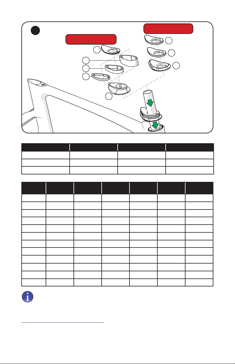
In order to successfully build the Venge ViAS bicycle, it is very important to
follow the order of operations as outlined in this guide. Modifying the order of
assembly will result in a much longer and more frustrating build process, with
less than optimal results.
WARNING! Many components on the Venge ViAS, including, but not limited to,
the handlebars, the stem, and the brakes, are proprietary to the Venge ViAS.
Only use originally supplied components and hardware at all times. Use of
other components or hardware will compromise the integrity and strength of
the assembly. Venge ViAS specific components should only be used on the
Venge ViAS and should not be used on bicycles other than the Venge ViAS.
Failure to follow this warning could result in serious injury or death.
BOLT SIZE / TOOLS / TORQUE SPECS
WARNING! Correct tightening force on fasteners (nuts, bolts, screws) on your
bicycle is important. If too little force is applied, the fastener may not hold
securely. If too much force is applied, the fastener can strip threads, stretch,
deform or break. Either way, incorrect tightening force can result in component
failure, which can cause you to lose control and fall.
Where indicated, ensure that each bolt is torqued to specification. After your
first ride, and consistently thereafter, recheck the tightness of each bolt to
ensure secure attachment of the components. The following is a summary of
torque specifications in this guide:
LOCATION Bolt Spec Torque (in-lbf) Torque (Nm)
Stem @ Steerer Tube 4mm 45 5.1
Stem @ Handlebar 5mm 100 11.3
Stem cable guides (bolted to each other) 2mm
Stem cable guides (bolted to stem) 3mm 45 5.1
Garmin mount bracket @ stem 2.5mm 25 2.8
Garmin mount @ bracket 2.5mm 25 2.8
Front brake mounting bolts 4mm 55 6.2
Front brake cable pinch bolt T10 Torx
Rear brake mounting bolts 5mm 70 7.9
Rear brake cable pinch bolt 4mm 45 5.1
Brake pads 5mm 55 6.2
Fork expander plug 4mm 45 5.1
Bottom bracket door (Di2 only) 2.5mm 10 1.1
Bottom bracket door (Carbon - mechanical or electronic) 2.5mm 15 1.7
Saddle rail clamp bolt 5mm 120 13.5
Seat collar bolt 5mm 55 6.2
Derailleur hanger 3mm 20 2.3
Brake pad / spring tension adjusters 2mm
Front brake cable release lever 2.5mm
Stem top cap 3mm

3
CAUTION: Ensure that all contact surfaces are clean and bolt threads are
greased or have a threadlocking compound (refer to the instructions for each
bolt) prior to installation.
The following tools are required for installation of this product:
2, 2.5, 3, 4, 5mm Allen keys
3, 4, 5mm socket Allen keys
ReachR, PullR, PointR tools
Torque wrench
High-quality grease
Blue threadlocker (Loctite 242)
Cable and housing cutters
Flathead screwdriver (notched)
The ReachR, PullR and PointR tools are custom tools designed to aid in the efficient and correct
assembly of the Venge ViAS bicycle.
GENERAL NOTES ABOUT RIDING AND MAINTENANCE
The Venge ViAS is a high performance bicycle that requires regular maintenance by your
Authorized Specialized Retailer. For general information regarding maintenance of your bicycle,
please refer to section 5 of the Owner’s Manual. In addition, routinely perform the Mechanical
Safety Check described in section 1.C of the Owner’s Manual before each ride.
CAUTION: While riding, listen for any creaks, as a creak can be a sign of a
problem with one or more components. Periodically examine all surfaces in
bright sunlight to check for any small hairline cracks or fatigue at stress points,
such as welds, seams, holes, and points of contact with other parts. If you hear
any creaks or discover any cracks, no matter how small, immediately stop
riding the part and have it inspected by your Authorized Specialized Retailer.
WARNING! Great care should be taken to not damage carbon fiber or
composite material. Any damage may result in a loss of structural integrity,
which may result in a catastrophic failure. This damage may or may not be
visible in inspection. Before each ride, and after any crash, you should carefully
inspect your bicycle for any fraying, gouging, scratches through the paint,
chipping, bending, or any other signs of damage. Do not ride if your bicycle
shows any of these signs. After any crash, and before you ride any further, take
your bicycle to an Authorized Specialized Retailer for a complete inspection.
CAUTION: Do not face or ream the bottom bracket shell! This can prevent
proper installation of the crank. Your Specialized frame does not require any
bottom bracket shell pre-installation preparation, as all surfaces have been
precisely machined to specific tolerances at the factory for proper interface
with OSBB/BB30 compatible crankset.
WARRANTY
For the complete warranty provisions, please refer to www.specialized.com.

4
STEM / STEERER TUBE PARTS
Many small parts for the stem and steerer tube are etched with one or more icons to denote if the
part is for mechanical ( ) or electronic ( ) shifting (exceptions include the spacer stack parts
and the steerer tube expander plug).
The Venge design offers a wide range of frame and component options to help the rider find the
perfect position. This range is provided through a combination of the following variables:
• Frame stack and reach - 7 size options: 46, 49, 52, 54, 56, 58, 61cm
• Spacer stack - 15 stack options: 6.5-75.5mm in 5mm increments
• Stem length - 7 options: 70, 85, 95, 105, 115, 125, 135mm
• Handlebar rise - 8 options: 0, 25mm rise x 38, 40, 42, 44cm width
• Seatpost length/setback - 6 options: 330, 380mm length x 0, 20, 35mm setback
STEM TOP CAP
S164800008
VENGE STEM
70mm: S164800013
85mm: S164800014
95mm: S164800015
105mm: S164800010
115mm: S164800011
125mm: S164800012
135mm: S164800016
STEM SHIM
MECHANICAL SHIFT : S164800001
ELECTRONIC SHIFT: S164800002
EXPANDER PLUG
S162500007
COMPRESSION RING
MECHANICAL SHIFT: S162500004
ELECTRONIC SHIFT: S162500002
CABLE GUIDE - BRAKE / SHIFT
S164800003
VENGE SEATPOST
380 x 0mm: S164900001
380 x 20mm: S164900002
380 x 35mm: S164900003
330 x 0mm: S164900006
330 x 20mm: S164900007
330 x 35mm: S164900008

5
STEERER TUBE SPACER (LOW STACK)
HEIGHT: 5mm
S162500020 (x2)
STEERER TUBE TOP CAP (LOW STACK)
HEIGHT: 6.5mm
S162500022
TOP SPACER (HIGH STACK)
HEIGHT: 4mm
S162500018
STEERER TUBE SPACER (HIGH STACK)
HEIGHT: 5mm
S162500016 (x1)
STEERER TUBE SPACER (HIGH STACK)
HEIGHT: 10mm
S162500012 (x1)
STEERER TUBE SPACER (HIGH STACK)
HEIGHT: 20mm
S162500014 (x2)
STEERER TUBE TOP CAP (HIGH STACK)
HEIGHT: 16.5mm
S162500010
VENGE AEROFLY HANDLEBAR (0mm RISE)
38cm: S160800008
40cm: S160800001
42cm: S160800002
44cm: S160800003
VENGE AEROFLY HANDLEBAR (25mm RISE)
38cm: S160800007
40cm: S160800004
42cm: S160800005
44cm: S160800006
LOW STACK: Choose the LOW STACK TOP CAP (S162500022 - 6.5mm tall). Add either one
or two 5mm low stack spacers.
HIGH STACK: Choose the HIGH STACK TOP CAP (S162500010 - 16.5mm tall) and the HIGH
STACK TOP SPACER (S162500018 - 4mm tall). Add the desired combination of high stack
spacers (5/10/20mm spacers, total 0 to 55mm) between the top cap and the top spacer.

6
1. FRAME FIT
A. DETERMINING FIT
Install the drivetrain on the frame (bottom bracket, crank, pedals, rear wheel, derailleurs and chain).
A
1
2
3
B
C
Fig.1: Install the lower headset bearing
A
(S162500008) on the fork.
Fig.2: Install the fork in the head tube.
Fig.3: Install the upper bearing
B
(S162500005).
Fig.3: Install the compression ring
C
(S162500002 or S162500004).
Brake guide: back
Mechanical:
S164800001
Electronic:
S164800002
Shim slot: front
4
Fig.4: Install the stem shim
D
(S164800001 or S164800002) into the stem. Make sure the
etchings are on top and the arrow is pointing toward the front of the bike.

7
5
F
F
E
G
H
I
J
K
LOW STACK OPTION:
6.5-16.5mm
HIGH STACK OPTION:
20.5-75.5mm
LOW STACK OPTION:
STACK HEIGHT 6.5mm LS TOP CAP (E) 5mm LS SPACER (F) 5mm LS SPACER (F)
6.5mm X
11.5mm X X
16.5mm X X X
HIGH STACK OPTION:
STACK
HEIGHT
16.5mm HS
TOP CAP (G)
5mm HS
SPACER (H)
10mm HS
SPACER (I)
20mm HS
SPACER (J)
20mm HS
SPACER (J)
4mm TOP
SPACER (K)
20.5mm X X
25.5mm X X X
30.5mm X X X
35.5mm X X X X
40.5mm X X X
45.5mm X X X X
50.5mm X X X X
55.5mm X X X X X
60.5mm X X X X
65.5mm X X X X X
70.5mm X X X X X
75.5mm X X X X X X
Specialized recommends using a stationary trainer and working with an
experienced fit professional. Since the fork must be cut to the correct height
before the bike can be built and ridden, determining the proper fit is more
important than with a traditional bike.
To help transfer measurements from a current bike, use the Venge ViAS Sizing tool, located at
https://www.retul.com/venge-vias-sizing/
Install the front wheel and place the bike in a stationary trainer.
Fig.5: If stack/reach are already known measurements, choose the spacers (low stack or high
stack), stem and handlebar that correspond to the desired stack/reach.

8
If stack/reach are not yet known measurements, start experimenting with different spacer
stacks, stem lengths, handlebar heights/widths and handlebar/brake lever positions.
Fig.5: Assemble the chosen spacer stack in order. The spacers are keyed to fit either the low
or high stack configuration. Low and high stack parts cannot be interchanged.
6
L
7
N
M
Mark position
Lower
edge:
No gap
Upper
edge:
Large
gap
8
Fig.6: Install the stem
L
onto the steerer tube (the steerer tube will stick out the top of the stem,
which is ok at this time). Do not torque! Tighten the bolts enough so that the stem doesn’t move.
Fig.7: Apply carbon friction paste to the surfaces between the stem, faceplate and handlebar.
Install the handlebar
N
against the stem. Adjust the angle of the handlebar until it’s in the
desired position.
Fig.8: While holding the handlebar in its desired position, rotate the faceplate downward so
that there is no gap between the faceplate and the stem body, at the underside of the stem.
The gap should only be above the handlebar. Torque the stem bolts to 100 in-lbf (11.3 Nm).
If the faceplate is not bottomed against the lower edge of the stem, the
faceplate and handlebar can rotate downward under rider weight until the
faceplate bottoms out against the stem below the handlebar.
Fig.7: Install the brake levers
M
and adjust the angle until they’re in the desired positions.
Fig.7: Once the stack/reach and handlebar/brake lever angle positions are determined, mark
the handlebar and lever positions, then disassemble the handlebar from the stem.
B. ADJUSTING SADDLE AND SEATPOST POSITION
1
2
Fig.1: Apply grease as illustrated to the surfaces between the upper and lower wedge, as well
as the barrel. bolt threads and bolt head.
Fig.2: Insert the wedge assembly into the seat tube.
Fig.2: Apply carbon friction paste to the seatpost, then insert into the seat tube. The use of
carbon friction paste is required.

9
7x9mm
7x7mm
3
ANGLED SURFACES
A
F
B BC CD
E
Tab into groove Align arrows
Fig.3: Apply grease as illustrated to the conical surfaces
C
of the clamp mechanism, then
install them in the seatpost
D
.
Engage the saddle rails into the slots of the conical portions of the clamp mechanism.
Ensure that the wedges are parallel to each other. If the wedges are offset
relative to each other, they can force the saddle rails to twist, which can result
in permanently bent rails and an uneven saddle position.
Place the outer cap portions
B
of the clamp mechanism over the saddle rails.
The seatpost hardware is available for 7x7mm round alloy rails, or 7x9mm oval
carbon fiber rails.
Install the nut
A
. To avoid damage to the clamp mechanism, the arrows must align
F
to
ensure the tab is placed in the groove of the outer cap.
Fig.3: Install the bolt
E
. Use blue threadlocker (Loctite 242) on the threads, place into the
opposite side outer cap and thread into the nut. Tighten lightly.
Remove all burrs and square edges from the seat tube and seatpost surfaces in contact each
other. These edges and burrs can dig into the material, compromising the strength of the carbon.
Remove any grease from the internal surface of the seat tube. Composite
seatposts are non-metallic, and cannot seize in the seat tube. Applying grease
reduces the friction that is critical to proper seatpost grip.
Apply carbon friction paste to the seatpost and seatpost wedge surfaces. A dry or
greased interface can cause the seatpost to slip.
WARNING! The seatpost is marked with a minimum insertion line. This is the
minimum amount of insertion required for the seatpost to remain structurally sound.
Please refer to the Owner’s Manual for additional seatpost installation information.
Install the seatpost into the seat tube.
Adjust the saddle to the desired angle and fore-aft position.
Fig.3: Torque the seatpost bolt to 120 in-lbf (13.5 Nm).
Adjust the seatpost to the desired height for proper leg extension.
Fig.2: Torque the seat collar to 55 in-lbf (6.2 Nm).

10
2. FRAME ASSEMBLY
Mechanical shift routing: page 10-11
Electronic shift routing: page 12-13
FRAME HOUSING - RECOMMENDED STARTING LENGTH
REAR BRAKE (RED) REAR DERAILLEUR (GREEN) FRONT DERAILLEUR (BLUE)
110cm 165cm 90cm
A. INSTALLING BRAKE / SHIFTER HOUSINGS IN FRAME (mechanical)
1
RED:
Rear Brake (RB)
GREEN:
Rear Derailleur (RD)
BLUE:
Front Derailleur (FD)
A
C
B
The following housing lengths are for the initial installation, for all frame sizes.
Once routed, the housings must be trimmed according to the instructions.
While order of installation is not critical, it’s recommended to follow the order
below.
Fig.1: REAR BRAKE - Slightly curve the leading edge of a section of brake housing
A
(see
chart above for recommended housing length), then insert the housing starting at the seat
tube exit port. Continue to run the housing up the down tube until it exits at the head tube.
Fig.1: REAR DERAILLEUR - Slightly curve the leading edge of a section of shift housing
B
(see
chart above for recommended housing length), then insert the housing into the chainstay. Route
the housing over the bottom bracket shell and up the down tube until it exits at the head tube.
Fig.1: FRONT DERAILLEUR - Install a section of shift housing
C
(see chart above for specific
housing length) up the down tube until it exits at the top of the head tube.
Make sure the cable housings aren’t winding around each other in the down tube. Shine some light
into the down tube from the bottom bracket cable guide hole to make sure they’re not crossing.
Make sure the ends of the housings are clean cut with no metal burrs, and that the inner sheaths
have been fully opened using a pick or other narrow object.
Install a section of foam tubing over each length of cable housing to ensure the housings don’t
rattle in the down tube.

11
2
Tape
together
3
Tape
together
Fig.2: Re-install the upper headset bearing.
Fig.2: Insert the front derailleur and rear brake housings into their respective slots in the
compression ring, then tape the housings together.
Fig.3: Insert the rear derailleur housing into the 3rd slot, then tape it to the other two housings.
4
105-115mm
5
A
B
Fig.4: Apply grease as illustrated to the upper headset bearing, then seat the compression ring
into the upper bearing.
Fig.5: Trim the front derailleur housing
A
so that 105-115mm of housing exits at the bottom
bracket cable guide port.
Fig.5: Insert the front derailleur housing into the housing guide
B
at the bottom bracket.
Avoid tugging on the housings to seat the compression ring (Fig.4). Too hard of
a tug will pull the housings out of the compression ring. A bit of excess housing
length in the down tube is ok.
Test the cable housing openings to make sure cables can enter and exit the
cable housings cleanly.

12
A. INSTALLING BRAKE / SHIFTER HOUSINGS IN FRAME (electronic)
ELECTRONIC WIRING LENGTH CHART
WIRING LOCATION WIRING LENGTH WIRING LOCATION WIRING LENGTH
Front Derailleur 500mm Shifters (x2) 350mm
Rear Derailleur 700mm Down Tube 1200mm
Battery (Seatpost) 1000mm
FACTORY ROUTING: Junction B inside handlebar, junction A under bottom bracket
A
.
1
BROWN:
Electric wiring (ED)
A
RED:
Rear Brake (RB)
B
Fig.1: Install a section of brake housing
B
(see chart on page 10 for specific housing
length), starting at the rear brake exit port. It helps to give the cable housing a slight bend
before feeding it into the seat tube exit port. Continue to run the housing into the frame until it
becomes visible at the head tube, then guide it out the top of the head tube.
2
C
DE
F
G
Fig.1 & 2: Route the wires through the chainstay
C
, seat tube (battery
D
and front derailleur
E
)
and down tube
F
, over/in front of the bottom bracket, then connect the wires to the junction A box.
Use the BB guide door
G
designed specifically to contain the junction A box.

13
ALTERNATE ROUTING: Junction A attached to Garmin bracket, Junction B
A
inside down tube.
B
3
4
Fig.3: Install a section of brake housing
B
(see chart on page 10 for specific housing
length), starting at the rear brake exit port. It helps to give the cable housing a slight bend
before feeding it into the seat tube exit port. Continue to run the housing into the frame until it
becomes visible at the head tube, then guide it out the top of the head tube.
Fig.3 & 4: Route the wires through the chainstay, seat tube (battery and front derailleur) and
down tube, over/in front of the bottom bracket, then connect the wires to the junction B box.
Place the junction B box into the down tube, then install the BB door.
5
Fig.5: Apply grease as illustrated to the upper headset bearing, then seat the compression ring
into the upper bearing.
Fig.5: Place the brake housing and shift wire into their respective slots in the compression ring.
Fig.5: Grease, then place the compression ring into the upper headset bearing, with the arrow
pointing toward the front of the bike.
Avoid tugging on the brake housing to seat the compression ring (Fig.5). Too
hard of a tug will pull the housing out of the compression ring. A bit of excess
housing length in the down tube is ok.
Test the cable housing openings to make sure cables can enter and exit the
cable housing cleanly.

14
B. INSTALLING REAR BRAKE
1
A
B
Fig.1: Align the spring tabs with the spring holes, then install the brake arms
A
on the frame.
Tighten the brake pivot bolts
B
to 70 in-lbf (7.9 Nm).
2
C
130mm
50mm
Sheath
D
Fig.2: Cut the exposed brake housing approximately 50mm from the exit port, then place a
barrel adjuster
C
onto the exposed section of housing.
Fig.2: Insert another section of cable housing into the barrel adjuster, then trim the housing
so that the overall length exiting the seat tube exit port is 130mm.
Fig.2: Install a brake cable sheath
D
into the housing slot of the non-drive-side brake arm.
Fig.2: Insert the end of the brake cable housing into the brake arm’s housing slot. Make sure
the housing has a slightly curved path from the frame to the brake arm.

15
3. FORK ASSEMBLY
A. CUTTING STEERER TUBE
Reinstall the fork in the head tube according to the steps in Chapter 1, Section A.
“DETERMINING FIT”, page 6. Be careful not to move the compression ring, keep it
properly seated in the upper headset bearing.
1
A
2
A
B
3
B
C
STEM
EXPANDER
PLUG
STEERER
TUBE
STEM SHIM
3mm MAX
1mm
Fig.1: Mark the steerer tube at the top of the stem shim
A
.
Remove the stem and parts (set aside for future installation).
Fig.2 & 3: Remove the fork and cut the steerer so that when installed, the top of the expander
plug is 0-3mm
C
below the top of the shim. The expander plug lip is 1mm thick
B
.
If the steerer tube extends above the shim, it can result in contact between the
expander plug and the stem cap, which can prevent proper headset adjustment.
Inspect the fork and stem to ensure that there are no burrs or sharp edges that can damage the
surfaces in contact with each other. Remove any burrs or sharp edges using fine grit sandpaper.
WARNING! Burrs and sharp edges can damage the carbon and alloy surfaces
of the components. Any deep scratches or gouges in the stem or fork can result
in component failure, which can cause you to lose control and fall.

16
WARNING! Do not apply carbon friction paste to the interface between the
stem and the steerer tube. Carbon friction paste at this location can result in
steerer tube failure which can cause you to lose control and fall.
B. INSTALLING FRONT BRAKE HOUSING
1BA
450mm
2
B
3
B
Fig.1: Cut a section of brake housing
A
450mm long, then install a brake cable in the housing
until the cable head
B
stops against the housing.
Fig.1: Bend the tip of the cable slightly to help guide the cable and housing up into the steerer
tube. Insert the cable tip into the fork, starting at the exit port hole at the drive-side front brake
mount location. Work the cable up into the fork crown, and up the steerer tube.
Fig.2: Once the cable exits the fork out the top of the steerer tube, pull on the cable exiting
the top of the steerer tube to pull the housing into the fork.
Fig.3: Once the housing extends past the top of the steerer tube, remove the cable from the
inside of the housing.
Disassemble the steerer tube expander plug
C
(S162500007).
4
Housing
hole
A
4mm Allen
key hole
Housing
set screw
Top
view
C
Bottom
view
D
5
A
D
Bottom
To p
Fig.4: With the set screw (fig.5
D
) fully backed out, insert the cable housing exiting the top of
the steerer tube into the housing hole at the bottom side of the lower wedge.

17
Fig.5: Tighten the set screw
D
on the top side of the wedge. This will engage the set screw
threads into the rubber outer sheath of the brake housing, securing the housing in place.
6
Lower wedge
Sleeve
Expander bolt
Upper
wedge
7
Fig.6: Reassemble the expander plug, then insert the expander plug into the cut steerer tube.
Fig.7: While pressing the expander plug into the steerer tube, lightly pull on the cable housing
from the brake exit port, to help guide the housing through the fork and prevent any kinks from
forming in the housing.
8
Align PointR
tool toward
front of bike
E
F
G
9
Align
PointR tool
toward front
of bike
The PointR tool
E
is a long custom Allen key designed to help align the
expander plug with the fork and stem (kit includes ReachR tool).
Table of contents