VIASONIX FALCON PRO User manual

FALCON
PRODUCTFAMILY
Service Manual
0344
Doc: VS0152, Rev 1.2

Falcon Service Manual
___________________________________
2
Copyright
Falcon/Pro, Falcon/Quad and Falcon/ABI+ are trademarks of Viasonix Ltd. This manual and its'
contents are the sole property of Viasonix Ltd. Reproduction in any form of the manual or its’ content, in
whole or in part, whether in English or in any other language, is strictly prohibited without the prior
written consent of Viasonix Ltd.
VS0152, rev 1.3 Page

Falcon Service Manual
___________________________________
3
TABLE OF CONTENTS
1 - INTRODUCTION ..................................................................................................................................5
1.1 ABOUT FALCON .............................................................................................................................5
1.2 ABOUT THIS MANUAL ....................................................................................................................5
1.3 SERVICE PERSONNEL.....................................................................................................................6
1.4 WARNINGS AND CAUTIONS............................................................................................................6
2 – TECHNICAL INFORMATION...........................................................................................................9
2.1 OVERVIEW .....................................................................................................................................9
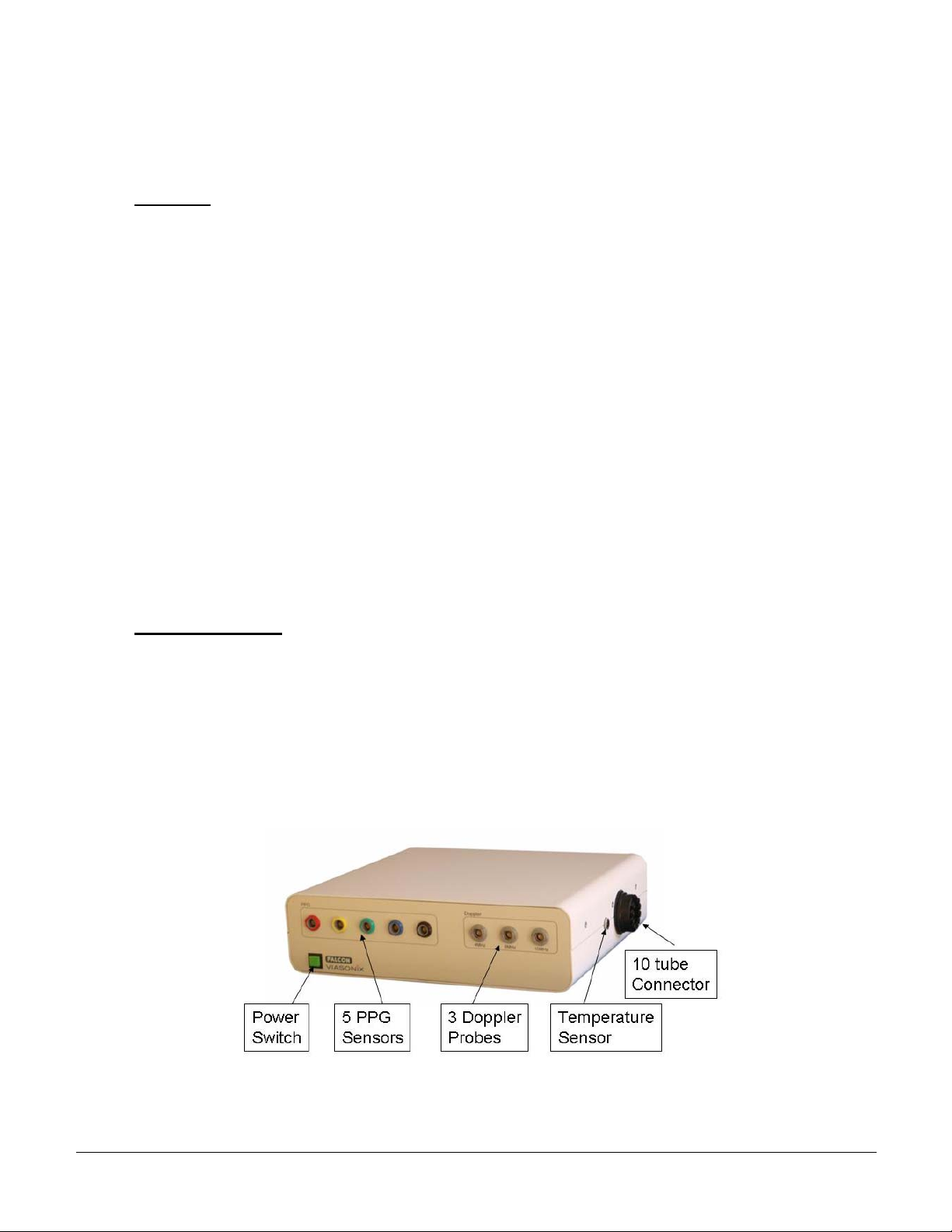
2.2 FALCON DESCRIPTION ...................................................................................................................9
3 – FALCON SERVICE AND REPLACEMENT PARTS....................................................................11
3.1 FALCON SERVICE KIT ..................................................................................................................11
3.2 FALCON REPLACEMENT PARTS ...................................................................................................12
4 – FALCON PERFORMANCE DIAGNOSTIC TESTING.................................................................13
4.1 TUBE CONNECTION TEST............................................................................................................13
4.2 VERIFY CALIBRATION TEST .......................................................................................................14
4.3 CALIBRATION ..............................................................................................................................14
4.4 REPEAT VERIFY CALIBRATION TEST .........................................................................................15
4.5 PUMPS AND VALVES PERFORMANCE TEST.................................................................................15
4.6 PRESSURE LEAKAGE TEST..........................................................................................................16
4.7 CONTROLLED DEFLATE RATETEST ...........................................................................................16
4.8 AUTOMATIC CHECK VALVE TEST ..............................................................................................16
4.9 MANUAL CHECK VALVE TEST....................................................................................................17
4.10 PPG AC TEST..............................................................................................................................17
4.11 PPG DC TEST..............................................................................................................................17
4.12 PVR TEST....................................................................................................................................18
4.13 DOPPLER BACKGROUND NOISE TEST.........................................................................................18
4.14 DOPPLER SPECTRUM TEST..........................................................................................................18
4.15 TEMPERATURE TEST ...................................................................................................................19
5 – FALCON DISASSEMBLY.................................................................................................................19
5.1 REMOVE THE TOP COVER...........................................................................................................19
5.2 RELEASE THE TUBES FROM THE PUMPS.....................................................................................20
5.3 REMOVE THE PUMP CABLE CONNECTORS.................................................................................21
5.4 RELEASE THE PUMP SUB-ASSEMBLIES .......................................................................................22
5.5 DISCONNECT THE TUBES.............................................................................................................22
5.6 DISCONNECT INTERNAL CABLE CONNECTORS...........................................................................23
5.7 RELEASE THE CW DOPPLER BOX...............................................................................................25
5.8 RELEASE THE FALCON BOARD ...................................................................................................27
5.9 RELEASE THE INTERNAL CABLES...............................................................................................29
5.9 REMOVE A CHECK VALVE ..........................................................................................................30
VS0152, rev 1.3 Page

Falcon Service Manual
___________________________________
4
6 – LEAKAGE SOURCE IDENTIFICATION.......................................................................................31
6.1 VALVE INVESTIGATION...............................................................................................................31
6.2 PUMP/TUBES INVESTIGATION.....................................................................................................32
7 – GENERAL INFORMATION.............................................................................................................33
3.1 DISCLAIMERS...............................................................................................................................33
3.2 REPLACEMENT PARTS .................................................................................................................33
VS0152, rev 1.3 Page

Falcon Service Manual
___________________________________
5
1 - INTRODUCTION
1.1 About Falcon
The Falcon product family includes the Falcon/Pro, Falcon/Quad and Falcon/ABI+ systems. The use of
the term Falcon in this manual relates to all 3 systems, unless specifically stated otherwise. The
Falcon/ABI+ system does not include Doppler options, and therefore all Doppler references in this
manual are not related to the Falcon/ABI+ system.
Falcon is an add-on non-invasive peripheral vascular diagnostic system, that plugs into a personal
computer via a USB connector for operation, data display and storage. Falcon systems incorporate
several technologies for the purpose of non-invasively diagnosing various arterial and venous
hemodynamic parameters in the peripheral circulation.
Falcon/Pro is the complete peripheral vascular diagnostic system. It includes 10 independent pressure
channels for the measurement of blood pressure (BP) or pulse volume recording (PVR). In addition, it
includes 5 independent photo-plethysmograph (PPG) channels, 1 skin temperature sensor, and 3
Continuous Wave (CW) Doppler pen-type probes with frequencies of 4 MHz, 8 MHz, and 10 MHz.
Falcon/Quad is a focused peripheral vascular diagnostic system. It includes 4 independent pressure
channels for the measurement of blood pressure (BP) or pulse volume recording (PVR). In addition, it
includes 4 independent photo-plethysmograph (PPG) channels, 1 skin temperature sensor, and 3 CW
Doppler pen-type probes with frequencies of 4 MHz, 8 MHz, and 10 MHz.
Falcon/ABI+ is a cost-effective peripheral vascular diagnostic system. It includes 4 independent pressure
channels for the measurement of blood pressure (BP) or pulse volume recording (PVR). In addition, it
includes 4 independent photo-plethysmograph (PPG) channels, and 1 skin temperature sensor.
The Falcon must be operated only by trained personnel. Falcon is intended for use only in adults and
children, and should not be used under any conditions for fetal or neonatal examinations.
1.2 About this manual
This manual assumes that the reader is a trained and experienced medical device service professional,
which is also familiar with peripheral vascular diagnostics and Doppler blood flow velocity
measurements. The manual does not provide any instructions relating to the techniques or methods of
acquiring data. The intention of this manual is to provide service instructions to the Falcon products, as
well as important warnings and precautions which are related to the safe use of the device. This manual
must be read completely by any Falcon service technician before attempting to perform any service
operations. If at any time the service procedure is not clear, immediately contact Viasonix Ltd. for further
instructions before attempting to proceed with the service.
The symbol is used in this manual to denote a warning that may have a hazardous effect on the
patient or user.
VS0152, rev 1.3 Page

Falcon Service Manual
___________________________________
6
The symbol !is used in this manual to denote a caution that may have a hazardous effect on the
equipment.
This manual gives instructions for the servicing of the Falcon, including diagnostic sequences to
troubleshoot and isolate basic failures, assembly sequences required to remove and replace suspect service
parts, and performance verification sequences to ensure that the performance of the repaired unit meets
the required specifications. This manual does not include any servicing capability for the ultrasound
probes, PPG and temperature sensors, pressure cuffs and tubing, cables or accessories. These items are
not serviceable. This manual is not intended to provide detailed repair procedures and technical
documentation to isolate failures to the lowest possible level. It is also not intended to support the
remanufacture and resale of the Falcon by third parties.
1.3 Service Personnel
This manual is intended for use by biomedical instrumentation technicians and other individuals who are
familiar with the routine servicing and maintenance of medical electronic instrumentation. Those
individuals should also be thoroughly familiar with the Falcon User Manual.
The servicing personnel should also be proficient with the architecture, components and typical servicing
procedures for personal computers running the Microsoft Windows operating system. Customers are not
authorized to perform any service to the system during the warranty period of the product.
Viasonix Ltd. understands the importance of feedback to continual quality improvement, and encourages
users and servicing personnel to provide any suggestions for improving the products and this manual.
1.4 Warnings and cautions
Take care to carefully read the following section. Additional warnings and precautions may also
appear in the other parts of this manual.
Only experienced biomedical instrumentation technicians or other individuals who are familiar
with the routine servicing and maintenance of medical grade electronic instrumentation should service the
system.
Viasonix Ltd. shall have no liability for any incident resulting from improper servicing, or from
the use of any service parts that are not obtained by authorized Viasonix Ltd. sources of supply. Do not
use any ultrasound probes, PPG Sensors, temperature sensors, pressure cuffs, air tubes, foot switch,
remote control, power supply, or any other accessories that are not supplied by Viasonix Ltd. with the
Falcon system.
VS0152, rev 1.3 Page

Falcon Service Manual
___________________________________
7
Always disconnect the power cord from the power outlet before opening the system. Turn off the
power before performing other maintenance activities. Do not clean the system with a wet cloth. Do not
immerse the ultrasound probes in water or other liquids.
Use only the power supply that is supplied with the Falcon. Before turning the power on, make
sure that all cables and connectors are properly connected.
Do not use the system near flammable conditions. Keep away from water or other liquids. Do not
operate the system under non-approved environmental conditions.
Do not operate the system if the power cord or any other cable or connector is damaged.
Use the system only for valid medical reasons. Keep examination duration to as short as
ecessary.n
All external devices, including printers, that are used in conjunction with the system, must comply
ith IEC 60601.w
Place the system only on a flat and hard surface. Never place the system on a cloth, sponge or
imilar materials.s
The internal electronics of the system are sensitive to damage from electrostatic discharge (ESD).
Use appropriate precautions when opening and servicing the unit or handling electronic components and
subassemblies. To avoid ESD (Electrostatic Discharge) damag
re properly grounded before touching any internal materials. e to sensitive components, make sure you
ystem components, make sure that you connect them in their proper location.
Turn off the power before cleaning. Clean the system only with a soft cloth or brush.
a
!Turn off the power before connecting or disconnecting any accessories. When re-connecting
s
!
VS0152, rev 1.3 Page

Falcon Service Manual
___________________________________
8
!Replace wire ties and reroute wires as they were initially found. Do not leave loose hardware or
tools inside the console. Do not attempt to change or modify the Falcon hardware.
!Conduct normal in-house product safety testing for the system after servicing and before returning
the unit for use on patients.
!Transferring a copy of the Falcon installation program and/or the installation serial number to
people or entities which did not purchase the Falcon system is strictly prohibited.
!Never drop the system or any of its' components. Take special care to prevent the ultrasound
probes and the PPG and temperature sensors, from dropping or knocking on a hard surface in order to
prevent mechanical damage.
!Do not run any other applications on the computer when operating the Falcon. Make sure all other
applications are turned off.
!Never pull on the cables for disconnecting the probes, sensors or other accessories.
!Connect the system only to a personal computer that meets the minimum requirements.
VS0152, rev 1.3 Page

Falcon Service Manual
___________________________________
9
2 – TECHNICAL INFORMATION
2.1 Overview
This section outlines the basic technical features of the Falcon system. The Falcon is a peripheral
vascular system which is designed to be plugged to a host computer for operation. The Falcon main parts
consist of the main control board, an ultrasound unit with PCB mount Doppler connectors which is
connected to the main board via a flat cable (not available with the Falcon/ABI+), and pneumatic units
which primarily carry the inflating pumps.
The host computer should have the following minimum requirements: Windows XP or 7 operating
system, Intel® 3GHz Core™ 2 Duo processor, 2 GB memory, sound card and speakers, and at least 100
GB remaining free disk space on the hard drive.
Operator control over the system can be accomplished through the keyboard, mouse, remote control or
foot switch which are connected directly to the computer, or through touch screen operation. The system
display should be 19’’ or higher wide screen with touch screen capabilities. The recommended display
resolution is 1280x720 pixels. The display provides the user with direct visual feedback regarding the test
performed, examination protocol, active sensors, examined site, signal display region, signal control
buttons and settings, and measured parameters.
2.2 Falcon description
A view of the front of the Falcon/Pro main console is given below. Note that the right side of the Falcon
is similar for all 3 systems. The front panel, however, shows the system name and logo according to the
specific Falcon system. In addition, the black PPG connector (the most right PPG connector in the PPG
connector row) is absent in the Falcon/Quad and Falcon/ABI+ systems. Furthermore, the Falcon/ABI+
system also does not have the 3 Doppler connectors as displayed below.
VS0152, rev 1.3 Page

Falcon Service Manual
___________________________________
10
A view of the back panel of the Falcon console is given below. Note that the back panel for all 3 Falcon
products is similar (excluding the designated system label).
Iso-Potential
Plug (optional) Power
Inlet USB
Connecto
r
The Falcon housing is designed to comply with applicable global regulatory requirements for safety
(EN60601-1) and electromagnetic compatibility (EN60601-1-2). The primary housing is made from
metal. The top cover is secured to the unit with 3 screws on each side. Connectors and cables meet
applicable regulatory requirements and environmental conditions. The housing basically contains all of
the system electronics, pneumatic components, and air tubes. The system receives 12V DC power via a
desktop power supply that is approved for Falcon.
VS0152, rev 1.3 Page

Falcon Service Manual
___________________________________
11
3 – FALCON SERVICE AND REPLACEMENT PARTS
3.1 Falcon service kit
The Falcon service kit is required to perform the performance diagnostic tests and to assist in
disassembling the system. The basic elements of the kit are detailed in the table below.
Part # Part Name Picture Description
PVC0105 Wrench Tool
PVC0012 PPG-DC Simulator Device
PVC0013 Temperature Simulator Device
PVC0064 Falcon external 10-tube Sub-assembly
PVC0106 Calibrated External Pressure Sensor
VS0152, rev 1.3 Page

Falcon Service Manual
___________________________________
12
PVC0107 Test Pressure Chamber
PVC0108 Closed Loop Silicon Tube
3.2 Falcon replacement parts
The table below lists all of the Falcon sensors and replacement parts, which can be replaced by authorized
service personnel.
Part # Part Name
PVC0072 Falcon 4 MHz CW Doppler Probe
PVC0073 Falcon 8 MHz CW Doppler Probe
PVC0074 Falcon 10 MHz CW Doppler Probe
PVC0075 Falcon PPG Fingerclip Sensor
PVC0076 Falcon PPG Disc Sensor
PVB0070 Adult skin Temperature Sensor
PVB0073 Hokanson Brachial cuff SC10
PVB0074 Hokanson Thigh cuff SC12
PVB0075 Hokanson Digit cuff UPC2.5
PVC0091 Falcon Remote Control
PVB0076 Phillips 3 Pedal Foot Switch
PVC0056 Falcon Adhesive Stickers (Roll of 1000)
PVC0064 Falcon external 10-tube Sub-assembly
PVC0103 Falcon Internal 10-tube Sub-assembly
PVC0057 Falcon Internal PPG Cable
VS0152, rev 1.3 Page

Falcon Service Manual
___________________________________
13
PVC0060 Falcon Internal Temperature Cable
PVC0071 Falcon Doppler Internal Flat Cable
PVC0067 Falcon/Pro Pump Sub-assembly Front
PVC0068 Falcon/Pro Pump Sub-assembly Back
PVC0069 Falcon/Quad Pump Sub-assembly Back
PVC0018+ Housed CW Doppler Board
PVC0080 PPG Holder for cart
PVC0081 Doppler Probe Holder for cart
4 – FALCON PERFORMANCE DIAGNOSTIC TESTING
The initial step when attempting to service the Falcon, is to perform a complete system diagnostic
performance testing. The diagnostic performance is performed through the Falcon software, and requires
the use of a complete service kit.
The performance testing is conducted when the Falcon is connected to a computer which is loaded with
the Falcon software. At the end of the testing a PDF report that summarizes all of the test results can be
generated for documentation purposes.
To get started, turn on the Falcon power and start the Falcon software. From the main screen, click on the
little Help icon on the bottom right of the screen (the little “i”), and select
Service/Diagnostics/Performance. A window opens, requesting to enter the technician password.
NOTE – only authorized service personnel are allowed to perform any service activities with the Falcon.
The technician password is: via123$
After entering the correct PW, a window opens requiring to enter the system serial number (S/N) and the
testers’ name. In the S/N section enter in the first field the first 3 digits of the Falcon S/N, and in the
second field the last 2 digits (marking the production year). After pressing the OK button, the Falcon
diagnostics protocol is loaded to the main screen, and a Help page opens to explain the next test. A
similar help page opens before each step in the test protocol. The tester can reload the respective Help
page for each test at any time with the HELP button on the right hand side. Once the tester presses the
Start button, the first diagnostic test automatically starts. For each test, the text to the right of the protocol
list guides the tester on what to do or what to expect.
4.1 Tube Connection Test
Objective: The objective of this test is to check that all of the internal tubing in the Falcon are
connected correctly.
Setup: Prior to starting the test, the 10-tube sub-assembly (PVC0064) should be connected to the
Falcon, and the external side of all tubes (the cuff side) should be open to air.
VS0152, rev 1.3 Page

Falcon Service Manual
___________________________________
14
Test: Once the Start button is selected (or the Redo button if the test is repeated), all Falcon pumps
become active, and start inflation to open air. The online instructions on the side guide the tester
to close the air output of each colored air tube ending with the finger according to a specific color
order. Once the tube ending is closed with the finger, pressure should be generated in that specific
channel and the instructions guide the tester to the next tube.
Pass/Fail: Pass is considered when all of the tubes generate pressure according to the instructed
order. If a a specific channel does not generate pressure when shutting the tube, then the tester
should press the Fail button on the right.
Troubleshooting:
a) The external tube sub-assembly may be leaking. Replace PVC0064 and retest.
b) One of the pneumatic elements: valves, pumps or internal tubes, may be responsible for
leaking. Follow the instructions in the section for leakage source identification to pinpoint the
leakage source.
4.2 Verify Calibration Test
Objective: This test verifies the calibration of the pressure sensors.
Setup: Connect the external pressure sensor (PVC0106) in parallel to one of the 2 free tube ends of
the pressure chamber (PVC0107) tubing. Turn PVC0106 on by pressing the power on button (top
left button).
Test: Connect the free tube ending of PVC0107 to the tested pressure channel tube of PVC0064,
and press Ok to start test. The corresponding pump should inflate to a set target pressure. Wait
until a window opens and type in the respective field the pressure shown on the external pressure
sensor device PVC0106. Press Ok and to complete the test for the current channel. Press NEXT to
continue with the test of the next channel.
Pass/Fail: Pass is defined as a relative error of less then 5% between the tested channel pressure
and the external measured pressure.
Troubleshooting:
If the Verify Calibration Test cannot be completed due to failure to build a steady pressure in the
pressure chamber, then one of the pneumatic elements: valves, pumps or internal tubes, may be
responsible for the failure. Follow the instructions in the section for leakage source identification
to pinpoint the leakage source, and repeat the calibration test.
If the Verify Calibration Test fails, then the failed channel name becomes active in the protocol list
on the left hand side for the next Calibrate test. The failed channel needs to be calibrated, and then
repeat the calibration verification test.
4.3 Calibration
Objective: This procedure is carried out only when the calibration test fails, in order to re-calibrate
the pressure sensors of the failed channels.
Setup: Maintain the same setup of the previous Verify Calibration test.
VS0152, rev 1.3 Page

Falcon Service Manual
___________________________________
15
Test: : Connect the free tube ending of PVC0107 to the respective pressure channel tube of
PVC0064, and press Ok to start test. The corresponding pump should inflate to a set target
pressure. Wait until a window opens and type in the respective field the pressure from the external
device. Press Ok and wait for the pump to resume inflation to a second preset target pressure, and
the second time that the calibration window pens. Type again the new pressure shown on the
external device, and press Ok to complete the calibration for the current pressure channel. Press
NEXT to continue with next active pressure channel.
Pass/Fail: Not applicable for this test. The calibration will be verified in the next test.
Troubleshooting:
If the calibration process cannot be completed due to failure to build a steady pressure in the
pressure chamber, then one of the pneumatic elements: valves, pumps or internal tubes, may be
responsible for the failure. Follow the instructions in the section for leakage source identification
to pinpoint the leakage source, and repeat the calibration test.
IMPORTANT – After the calibration process is completed, exit the Falcon software, and then re-enter
the program and resume the diagnostic testing. This will ensure proper calibration. Otherwise the
calibration data will not be saved for the corresponding pressure channels.
4.4 Repeat Verify Calibration Test
Objective: This test becomes active only when 1 or more pressure channels required calibration.
The test verifies the calibration of the pressure sensors.
Setup: Maintain the same setup of the Verify Calibration test.
Test: Connect the free tube ending of PVC0107 to the tested pressure channel tube of PVC0064,
and press Ok to start test. The corresponding pump should inflate to a set target pressure. Wait
until a window opens and type in the respective field the pressure shown on the external pressure
sensor device PVC0106. Press Ok and to complete the test for the current channel. Press NEXT to
continue with the test of the next pressure channel tat was previously calibrated.
Pass/Fail: Pass is defined as a relative error of less then 5% between the tested channel pressure
and the external measured pressure.
Troubleshooting:
If calibration still fails, contact your authorized Viasonix representative.
4.5 Pumps and Valves Performance Test
Objective: This test is composed of 2 separate tests: Pump performance test, and fast deflation test.
The first test is to verify that the pressure chamber inflates adequately, and the second to verify
that the chamber deflates quickly when required.
Setup: It is possible to maintain the setup of the calibration tests. The external pressure device can
be turned off.
VS0152, rev 1.3 Page

Falcon Service Manual
___________________________________
16
Test: Connect the tube of the tested channel to the pressure chamber. Press Ok to start inflating
the chamber and wait while the chamber inflates and deflates automatically and freeze takes place.
Pass/Fail: Pass for the inflation test is considered when the pressure inflates to 240 mmHg in less
then 10 seconds. Pass for the fast deflation test is defined as deflation to less then 15 mmHg in
less then 10 seconds.
Troubleshooting:
In case of failure of either test, one of the pneumatic elements: valves, pumps or internal tubes,
may be responsible for the failure. Follow the instructions in the section for leakage source
identification to pinpoint the source of failure.
4.6 Pressure Leakage Test
Objective: This test is designed to verify that the pressure chambers are not leaking.
Setup: Maintain the setup of the previous test.
Test: : Press Ok to inflate the chamber and wait until automatic freeze takes place. The chamber
will inflate to a set target pressure, and then hold the pressure for up to a minute, before pressure
release and auto freeze.
Pass/Fail: Pass is defined as a pressure drop of less then 3 mmHg over the course of the 20 second
test duration.
Troubleshooting:
In case of failure of this test, one of the pneumatic elements: valves, pumps or internal tubes, may
be leaking. Follow the instructions in the section for leakage source identification to pinpoint the
source of leakage.
4.7 Controlled Deflate RateTest
Objective: This test is designed to verify that the controlled deflate rate is accurate.
Setup: Maintain the setup of the previous test.
Test: : Press Ok to inflate the chamber and wait until automatic freeze takes place. The chamber
will inflate to a set target pressure, and then start deflating at a constant rate of 3 mmHg/sec until
automatic freeze.
Pass/Fail: Pass is defined as a deflate rate within +/- 1.5 mmHg/sec of the required rate.
Troubleshooting:
In case of failure of this test, one of the pneumatic elements: valves, pumps or internal tubes, may
be leaking. Follow the instructions in the section for leakage source identification to pinpoint the
source of leakage.
4.8 Automatic Check Valve Test
Objective: This test verifies that the check valves are opened at pressure of 300 mmHg +/- 20%.
VS0152, rev 1.3 Page

Falcon Service Manual
___________________________________
17
Setup: Maintain the setup of the previous test.
Test: : Press Ok to inflate all chambers and wait until automatic freeze takes place. The chamber
will inflate to a set target pressure, and then deflate quickly until automatic freeze. In case the
tested check valve does not meet the required criteria after the first inflation session, the test is
automatically repeated for up to 4 more times.
Pass/Fail: Pass is defined as pressure chamber is between 275 and 315 mmHg. If the pressure is
greater than 315 mmHg, proceed with manual measurements with the external pressure sensor,
since the limits of the internal pressure sensor are reached.
Troubleshooting:
In case of pressure above 315 mmHg, proceed to perform the manual check valve test.
4.9 Manual Check Valve Test
Objective: This test verifies that the check valves are opened at pressure of 300 mmHg +/- 20%,
and is performed only if the automatic test shows pressures higher then 315 mmHg.
Setup: Maintain the setup of the previous test, but turn on the external pressure device.
Test: : Press Ok to inflate the tested pressure channel. Wait until a window opens and type in the
respective field the pressure from the external device. Press Ok to complete the test.
Pass/Fail: Pass is defined as pressure chamber is between 275 and 350 mmHg.
Troubleshooting:
In case of pressure above 350 mmHg, the check valve needs to be replaced.
4.10 PPG AC Test
Objective: This test verifies the AC performance of the PPG sensors.
Setup: Connect each PPG sensor to the respective PPG channel and perform a PPG measurement
on the same index finger.
Test: : Press Ok to start the PPG measurement and press freeze after several seconds of signal
acquisition.
Pass/Fail: Pass is defined when a smooth and oscillatory signal is obtained. If this criteria is not
met, press the FAIL button on the right.
Troubleshooting:
a) In case of Failure, try replacing the PPG sensor (PVC0075).
b) If failure persists, try replacing the internal PPG cable (PVC0057).
c) If failure persists, contact your authorized Viasonix service representative.
4.11 PPG DC Test
Objective: This test verifies the DC performance of the PPG sensors.
VS0152, rev 1.3 Page

Falcon Service Manual
___________________________________
18
Setup: Sequentially connect PVC0012 (PPG-DC Simulator Device) to each PPG channel.
Test: : Press Ok to start the measurement and wait for automatic freeze.
Pass/Fail: Pass is defined as DC reading of 21148 +/- 4.00 %..
Troubleshooting:
a) In case of failure try replacing the internal PPG cable (PVC0057).
b) If failure persists, contact your authorized Viasonix service representative.
4.12 PVR Test
Objective: This test verifies the PVR performance of the pressure channels.
Setup: Place a digit cuff (PVB0075) on the index finger ans sequentially connect it to each
pressure channel.
Test: Press Ok to start PVR measurement and press freeze after several seconds of signal
acquisition.
Pass/Fail: Pass is defined when a smooth and oscillatory signal is obtained. If this criteria is not
met, press the FAIL button on the right.
Troubleshooting:
a) In case of Failure, try relocating the digit cuff on the finger.
b) If failure persists, try to fasten stronger the luer connector og the cuff to the respective tube.
c) If failure persists, try replacing the digit cuff (PVB0075).
d) If failure persists, contact your authorized Viasonix service representative.
4.13 Doppler Background Noise Test
Objective: This test checks the Doppler background noise level.
Setup: Connect all Doppler probes to their respective connectors on the front panel.
Test: Press Ok to start the measurement and wait until automatic freeze.
Pass/Fail: Pass is definedcfor low background noise level of less then 2500 and voltage less then
0.85, and current less then 1.75.
Troubleshooting:
a) In case of Failure, try replacing the respective Doppler probe.
b) If failure persists, contact your authorized Viasonix service representative.
4.14 Doppler Spectrum Test
Objective: This test verifies the quality of the Doppler spectrum.
Setup: Connect all Doppler probes to their respective connectors on the front panel.
VS0152, rev 1.3 Page

Falcon Service Manual
___________________________________
19
Test: Press Ok to start the Doppler measurement and acquire a Doppler spectrum from the carotid
artery. This test requires knowledge of carotid insonation. Press freeze after several seconds of
signal acquisition.
Pass/Fail: Pass is defined when good quality of Doppler spectrum is obtained. If criteria is not
met, press the FAIL button on the right.
Troubleshooting:
a) In case of Failure, try replacing the respective Doppler probe.
b) If failure persists, contact your authorized Viasonix service representative.
4.15 Temperature Test
Objective: This test verifies the Temperature accuracy.
Setup: Connect PVC0013 (Temperature Simulator Device) to the temperature port.
Test: Press Ok to start the measurement and wait until automatic freeze.
Pass/Fail: Pass is defined as a temperature reading of 18.7 +/- 2.5%.
Troubleshooting:
a) In case of Failure, try replacing the internal temperature cable (PVC0060).
b) If failure persists, contact your authorized Viasonix service representative.
After completion of the Falcon performance diagnosis testing, the complete test report can be viewed or
printed to a hard copy through the PRINT button on the right hand side. The test procedure is also saved
to the database, and can be loaded for review at any time (file called: Falcon Dagnostics).
5 – FALCON DISASSEMBLY
IMPORTANT - After every Falcon service assembly, full system performance testing must be repeated
and completed successfully.
The following details the disassembly instructions for the Falcon system. The assembly process is merely
a reverse of the disassembly instructions provided here, and therefore is not detailed separately.
Prepare a large, flat and rigid working surface that is free from other items and that will be comfortable
for the disassembly process. Carefully place the Falcon on the working surface. Disconnect all of the
connectors and cables from the system. Verify that the USB cable and the power supply cable are
disconnected from the back panel. Also, verify that the temperature sensor and the counterpart of the 10-
tube connector with the colored air tube sleeve are disconnected from the right side of the Falcon.
Finally, disconnect all PPG sensors and Doppler probes from the front panel.
5.1 Remove the Top Cover
VS0152, rev 1.3 Page

Falcon Service Manual
___________________________________
20
a) Release slightly the Temperature nut which is located on the right side of the Falcon. Take
care not to completely release the nut. In order to avoid scratching of the casing, hold the tool at
roughly 90 degrees to the nut, and try to avoid touching the casing as shown below.
c) There are 3 black screws on each of the right and left sides of the Falcon. Use a standard
Philips screw driver to unscrew these screws as shown below, and place the screws aside to be
available for the assembly stage.
d)
c) Carefully lift the Top Cover of the Falcon, and place aside on a rigid surface where it is safe
from potential scratches.
5.2 Release the Tubes from the Pumps
In the Falcon/Pro the pumps are located in 2 rows of 5 or 6 pumps each on PVC0067 Falcon/Pro
Pump Sub-assembly Front and PVC0068 Falcon/Pro Pump Sub-assembly Back. In the
Falcon/Quad and Falcon/ABI+ there are 4 pumps on PVC0069 Falcon/Quad Pump Sub-assembly
Back. Each pump is wired on one end, and connected with a short silicon tube oriented towards
the middle of the system. The silicon tube is connected to the air exit of the pumps. Gently pull
off the tubes from each of the pump air exits as shown below.
VS0152, rev 1.3 Page
This manual suits for next models
2
Table of contents
Popular Medical Equipment manuals by other brands

Konica Minolta
Konica Minolta Pulsox-2 Multi Lingual Short Form Instruction Manual

DT Research
DT Research 139CS Basic operation guide

Harvest Healthcare
Harvest Healthcare HLB685 General User/ Safety Guide

Sirona
Sirona Orthophos XG 3D Ceph Service manual

Wonjin Muslan
Wonjin Muslan POWER RECOVERY user manual

geneye
geneye UPHO user manual