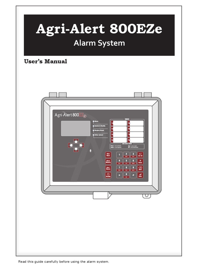
Viatron AGRI-ALERT 800T User manual

AGRI-ALERT 800T / AGRI-ALERT 800
ALARM SYSTEM
USER MANUAL

2AA-800 / AA-800T rev.03
WARNING: the warranty can be void if the Agri-Alert 800T or Agri-Alert-800 is used
in a manner not specified by the manufacturer.
Manufacturer:
Viatron Electronics
3514 1st Street,
St-Hubert (Quebec)
Canada
J3Y 8Y5

3
AA-800 / AA-800T rev.03
Table of Contents
CHAPTER ONE : USER INTERFACE ............................................................ 6
1.1 FRONT PANEL.................................................................................................. 6
1.2 MEANING OF STATUS LEDS.............................................................................. 7
1.3 DISPLAYING A PARAMETER .............................................................................. 7
1.4 MODIFYING A PARAMETER............................................................................... 8
1.5 HOW TO USE THE MENUS ................................................................................ 9
1.6 SYSTEM MESSAGES .......................................................................................10
1.7 BURGLAR ZONES ............................................................................................11
1.8 ACKNOWLEDGING AN ALARM .........................................................................12
1.9 TELEPHONE INTERFACE...................................................................................13
CHAPTER TWO: SYSTEM INITIALIZATION .............................................. 16
2.1 POWER UP .....................................................................................................16
2.2 SYSTEM CLOCK .............................................................................................16
2.3 USER ID MESSAGE .........................................................................................18
2.4 PASSWORD PROTECTION ................................................................................20
2.4.1 Modifying the Master Password............................................................ 20
2.4.2 Enabling / Disabling the Password Feature ............................................. 22
2.4.3 Modifying the User Passwords.............................................................. 23
2.4.4 Erasing All User Passwords.................................................................. 24
2.5 TEMPERATURE UNITS .....................................................................................25
2.6 16 VAC POWER FAILURE ALARM .....................................................................26
2.7 TEST PROCEDURE ..........................................................................................27
2.8 TROUBLE INFORMATION ..................................................................................28
2.9 STANDBY MODE .............................................................................................29
CHAPTER THREE: COMMUNICATION PARAMETERS................................. 30
3.1 INTRODUCTION ..............................................................................................30
3.2 DIALING INFORMATION ...................................................................................32
3.2.1 Busy Line Tries................................................................................... 32
3.2.2 Message Repetitions ........................................................................... 32
3.2.3 Call Start Delay .................................................................................. 32
3.2.4 Time Between Calls ............................................................................ 32
3.2.5 Restore Calls...................................................................................... 33
3.2.6 # of Call Repetitions............................................................................ 33
3.2.7 Alarm Recall Time .............................................................................. 33
3.2.8 Pause Delay ....................................................................................... 33
3.3 PHONE NUMBERS ...........................................................................................34
3.4 PULSE / TONE.................................................................................................38
3.5 ON SITE LISTENING .........................................................................................38
3.6 RINGS / ANSWERING MACHINE........................................................................40

4AA-800 / AA-800T rev.03
CHAPTER FOUR: ALARM PARAMETERS.................................................. 42
4.1 ALARM VALIDATION: SUMMARY OF EVENTS ...................................................42
4.2 SYSTEM ALARMS ...........................................................................................43
4.3 OUTDOOR TEMPERATURE COMPENSATION ON TEMPERATURE ALARMS .............44
4.4 ALARM MEMORY............................................................................................48
4.5 ZONE STATUS DISPLAY...................................................................................49
4.5.1 Viewing and Modifying Dry Contact Zones............................................. 49
4.5.2 Viewing and Modifying Temperature Zones............................................ 50
4.5.3 Viewing and Modifying Pulse Count Zones ............................................. 53
4.6 PARTITIONS ...................................................................................................55
4.7 BYPASS / ACTIVATE FUNCTION .......................................................................57
4.8 ENTRY DELAY ................................................................................................59
4.9 EXIT DELAY....................................................................................................60
4.10 SIREN DELAY................................................................................................61
TROUBLESHOOTING GUIDE .................................................................... 62
APPENDIX A: FUSE TYPES .................................................................... 64
APPENDIX B: MAXIMUM WIRE LENGTHS ............................................... 64
APPENDIX C: BACKUP BATTERY LIFE SPAN............................................ 64
GLOSSARY OF TERMS ........................................................................... 65
WIRING DIAGRAMS ............................................................................... 67
TECHNICAL SPECIFICATIONS ................................................................. 68
REGISTRATION CARD ............................................................................ 70

5
AA-800 / AA-800T rev.03
NOTICE
Every effort has been made to ensure that this manual is complete, accurate and up-
to-date. The information contained in it is subject to change without notice due to
further developments.
LIST OF TABLES AND FIGURES
Figure 1: Calling a Pager Number ..................................................................... 37
Figure 2: Outdoor Temperature Compensation ................................................... 44
Figure 3: Critical Temperature Monitoring ......................................................... 45
Figure 4: Monitoring the Indoor-Outdoor Temperature Difference ......................... 45
Figure 5: Example of Partitioning...................................................................... 55
Table 1: Pager Codes Used by the Agri-Alert System.......................................... 36
Table 2: System Alarms.................................................................................. 43

6AA-800 / AA-800T rev.03
CHAPTER ONE : USER INTERFACE
The system displays and prompts for information by using the alphanumeric screen.
The keypad is used for data entry and for enabling and disabling the various system
functions. The speaker on the front panel delivers voice messages. A built-in piezo-
electric warns of illegal entries (3 short beeps) and beeps once when a valid key is
pressed. The integrated microphone on the front panel is used to record the user ID
message and provide on-site listening. The status of some subsystems is displayed
using LEDs on the front panel.
1.1 FRONT PANEL
1 - Display Screen — An alphanu-
meric display used to provide infor-
mation and prompt for inputs.
2 - Cursor Keys — Used to step
through menu items during data en-
try and for deleting the last charac-
ter entered.
3 - Zone Status LEDs — Off: DIS-
ABLED; On: ACTIVATED; Slow Blink-
ing: BYPASSED; Fast Blinking:
ALARM.
4 - Speaker — Vocal system identifi-
cation and alarm messages.
5 - Integrated Microphone — Records the ID message and provides on-site listening
input.
6 - Keypad — User inputs and information requests.
7 - System LEDs — Status of various subsystems (see table on following page).
!
WARNING
Caution. Carefully read the following text for it contains important infor-
mation which, if ignored, may cause the controller to operate improperly.
Pay attention. The following text contains very useful information.
KEYS TO SYMBOLS IN THE MANUAL

7
AA-800 / AA-800T rev.03
1.2 MEANING OF STATUS LEDS
1.3 DISPLAYING A PARAMETER
When you select a parameter to input or modify, the system begins by displaying the
current value or status of the parameter. If the message to display is longer than the
size of the window, it will be scrolled to the left. The display pauses at the end of
each screen to allow time to read the message. You can exit prematurely from a
display sequence at any time by pressing the Cancel key. This will place you in
program mode and allow you to modify the parameter values (see next section). To
exit from this function as well, press the Cancel key once again.
DELGNINAEM
MRALA
erasnoitidnocmralaeromroenonehwdetavitcasiDELsihT
lenapehtfoedistfelehtnosDELenozlaudividniehT.detceted
.deepshgihtagniknilbtratsmralanisenozehtotgnidnopserroc
ehtsagnolsadegdelwonkcasimralaehtnehwffodenrutsiDELehT
ondnadespalesahemittesereht,stsixeregnolonnoitidnocmrala
.evitcaerasmralarehto
YBDNATS
.edomybdnatsnisimetsystrelAirgAehtnehwdetavitcasiDELsihT
mralarofstupnirosnesehtgnirotinomspotsmetsyseht,edomsihtnI
signirotinomlamronnehwffodenrutsiDELehT.snoitidnoc
.demuser
DESSAPYB
ehT.dessapyberasenozeromroenonehwdetavitcasiDELsihT
otgnidnopserroclenapehtfoedistfelehtnoSDELenozlaudividni
ffodenrutsiDELehT.deepswoltagniknilbtratssenozdessapybeht
.dessapybyltnerrucerasenozonnehw
DEMRA .demraerasenozralgrubehtnehwdetavitcasiDELsihT
ENILNO .enilenohpehtsesumetsysehtnehwdetavitcasiDELsihT
CAV61
ERULIAF
CAV61ehtnodetcetedsieruliafrewopanehwdetavitcasiDELsihT
.)remrofsnarttnuomllaw(tiucricylppus
YRETTABWOL .wolsiegatlovyrettabpukcabehtnehwdetavitcasiDELsihT
ELBUORT
:nehwdetavitcasiDELsihT
ehtmorfdeviecerlangisehthtiwstcilfnocnoitarugifnocenoza
rosnes
yrdroerutarepmetanodetcetedsitiucricneporotrohseriwa
.tupniRLOEhtiwtcatnoc
.detcetedsimelborperawtfosa

8AA-800 / AA-800T rev.03
ENTER NEW DELAY
_ MIN: _ _ SEC
RANGE FROM
(0 .. 5 MIN, 0 .. 59 SEC)
If a parameter is not completely defined when you try to display it, the message
INCOMPLETE DATA appears on the screen. This may be an indication that the sys-
tem will not behave as expected. If, for example, a zone input is not completely
configured, the system will not monitor the zone for alarm conditions. Before enabling
the system for normal operation, make sure all parameters are properly defined. In
the case of phone numbers and zones, the system will display a message every 3
seconds telling the user which zones and phone numbers are incomplete. To exit
from the warning display, press the Cancel key.
1.4 MODIFYING A PARAMETER
If you have selected a parameter and the display sequence is now finished, you can
begin modifying the parameter values. The following screen appears on the display:
This screen is also displayed if the display sequence described above was cancelled
prematurely. If you want to modify the parameter values at this point, press the Enter
key to modify the parameter. The system will prompt for the information re-
quired to define the parameter. When the parameter is defined by a numerical value,
a range of possible values is displayed. For example, if you select the Exit Delay
parameter followed by MODIFY, the system responds:
The number of spaces provided for input corresponds to the maximum number of
digits allowed. In this example, one space is provided for the minutes and 2 spaces
are provided for the seconds. The cursor positions itself on the first space and blinks
TO MODIFY. . . . . (↵↵
↵↵
↵)
TO QUIT. . . . . . . (X)

9
AA-800 / AA-800T rev.03
until a digit is entered. If no response is given within 2 minutes, the system will can-
cel the input session and return to the Date/Time display. If more than one value is
required in the same screen (in this example: hours and minutes), press Enter after
entering the first value to step to the following one. To enter a zero value, you cannot
simply press Enter; you must type 0 Enter.
If you make a typing mistake, you can backstep using the back arrow key under-
neath the display window before pressing Enter. The cursor will position itself accord-
ingly. You can enter a negative value if this is allowed (for example, a negative tem-
perature value) by pressing the +/- key either before or after the digits.
After entering a value using the numerical keypad, press Enter to register the value. If
the value entered falls outside the permissible range for that parameter, the system
will beep three times and wait for you to modify the input using the back arrow key.
PASSWORD
STATUS
DATE . . . . . . . . . (1)
TIME . . . . . . . . . (2)
1.5 HOW TO USE THE MENUS
Menus are used to select a parameter or to assign a predetermined value to a param-
eter. If the menu is comprised of only two items, they are displayed on the screen at
once. For example, when you press the Clock key
QZ-
Clock
, followed by Enter to modify,
the following menu appears:
You simply type the number of the item to select that item (no need to press the Enter
key). When more than two menu items are involved, the system will display one item
at a time and allow the user to scroll through the menu using the up and down-arrow
keys . Each menu item is followed by an arrow symbol to locate the current
position in the menu. Once a menu item is selected, other sub-menus may appear to
further define the input. For example, if you press the Password key . After
having entered the master’s password, the following sub-menu appears:

10 AA-800 / AA-800T rev.03
1.6 SYSTEM MESSAGES
When the display is not being used by the user, the system periodically scrolls various
status messages. If temperature zones are defined, the temperatures for those zones
are displayed, as well as the low set point (L), the high set point (H) (the critical tem-
perature (C) is also displayed if the outdoor compensation feature is enabled). When
alarms are detected, they are displayed as well, including system alarms such as a
battery failure or an unusual system temperature. When a zone or phone number is
improperly configured, it is identified along with the message “INCOMPLETE DATA”.
When burglar zones are armed, the message “BURGLAR ZONES ARMED” is displayed.
If the system clock has never been adjusted, the message “ADJUST CLOCK” is dis-
played. Pressing any key will stop the display sequence.
ZONE #3 75.0oF
L50 , H90 , C104
PASSWORD
MASTER
The first menu item is STATUS. The arrow following the item means you are at the
top of the menu. If you press the down-arrow , the second item appears:
The arrows indicate that menu items are to be found above and below the current
item. When you reach the end of the menu, the last item will have an up-arrow . To
select a menu item, press Enter.

11
AA-800 / AA-800T rev.03
1.7 BURGLAR ZONES
These zones are armed or disarmed as a group using a password. Two types of con-
figurations are possible depending on when alarms are to be declared. In an instant
burglar zone, alarms are declared as soon as they are detected. In a delay burglar
zone, alarms are declared only after an Entry Delay has elapsed. In this way, the
authorized user has time to disarm the burglar zones before an alarm is declared. This
delay is common to all delay burglar zones. Similarly, all zones are armed after the
Exit Delay has elapsed. The key sequence for arming or disarming is as follows:
followed by the password sequence
.
When the system is armed, the system starts beeping and the screen immediately
displays a countdown of the exit delay (in minutes and seconds). The keypad is
locked at this point: the only key sequence allowed is the disarming sequence. After
the exit delay has elapsed, the system is armed and alarms are immediately declared
as they are detected for all burglar zones. The system displays the message “BUR-
GLAR ZONES ARMED” periodically on the screen.
When an alarm occurs in a burglar zone with an entry delay, the screen displays a
countdown of the entry delay. During this time, the piezoelectric loudspeaker beeps
(the loudspeaker stops when the key sequence is entered). If no one has disarmed
the system after the entry delay has elapsed, an alarm is declared. Disarming will
affect all currently active burglar zones. The system displays the message “BUR-
GLAR ZONES DISARMED” on the screen.

12 AA-800 / AA-800T rev.03
ENTER PASSWORD
_ _ _ _
ENTER PASSWORD
_ _ _ _
1.8 ACKNOWLEDGING AN ALARM
In order to notify the Agri-Alert system that an alarm message has been received, the
alarm must be acknowledged. There are several ways of doing this. If you are on-
site when an alarm is detected, enter your password (if the password feature is en-
abled) or simply press <1> key on the front panel to acknowledge. You can also
acknowledge an alarm over the phone when the Agri-Alert system reports the alarm
(see below) or by calling the Agri-Alert system yourself between phone dialouts (if the
intercall time is greater than zero).
Acknowledging from the keyboard:
When an alarm is detected, the following message is displayed:
1. Press 1to acknowledge. If the alarm is not acknowledged from the keyboard
within 15 seconds and the dialout sequence is enabled for the zone in alarm, the
dialout sequence will be launched. If the password feature is enabled, the system
prompts for a password before acknowledging.
2. When a user acknowledges an alarm, the siren stops ringing. If the dialout se-
quence is completed and no acknowledgment has been received, the alarms are
automatically acknowledged but the siren continues to ring; it must be acknowledged
separately from the keypad. In this case, the following message is displayed:
3. Press 1to acknowledge or 2to exit without acknowledging. If the password
feature is enabled, the system prompts for a password before acknowledging.
If passwords are enabled and an incorrect password is entered, the keypad will lock
after 4 such tries. The keypad will unlock only after the alarm is acknowledged by
phone or at the end of the dialout sequence.
ACK ALARMS
PRESS . . . . . .<1>
ACK SIREN
PRESS . . . . . .<1>

13
AA-800 / AA-800T rev.03
1.9 TELEPHONE INTERFACE
The Agri-Alert system reports alarms over the phone. It can also be accessed over
the phone to obtain status reports. When calling the Agri-Alert, make sure the Ring
Until Answer and Answering Machine parameters are set properly (see Section 3.6).
Alarms: When an alarm occurs, the Agri-Alert system reports the alarm over the
phone to all the numbers programmed in its dialout sequence (see Chapter 3). The
following section outlines the dialogue session when a number is reached. A touch-
tone phone must be used to respond to the system prompts. When an alarm is ac-
knowledged, the Agri-Alert system stops dialing out. The system will hang up when
the session is over.
“Hello, this is Agri-Alert”
[User ID Message is played over the phone]
[Description of the alarm condition; for example: “Alarm Zone 1”]
“On-site Listening”
[Microphone input is sent over the phone for on-site listening if enabled]
“Enter your password to acknowledge alarm messages”
User enters four-digit password on the phone keypad. If an incorrect password is
entered, the system responds with “Wrong password”. The user has four tries in all
to enter the correct password. When the correct password is entered, the system
responds with “OK”.
“ To hang up — press 0
For on-site listening — press 2
For a new selection — press 8”

14 AA-800 / AA-800T rev.03
“Hello, this is Agri-Alert”
[User ID Message is played over the phone]
“Enter your password”
User enters four-digit password on the phone keypad. If an incorrect password is
entered, the system responds with “Wrong password”. The user has four tries in all
to enter the correct password. When the correct password is entered, the system
responds with “OK”.
“ For a complete status report — press 1
For a status report on a particular zone — press 2
For on-site listening — press 4
For a new selection — press 8
To hang-up — press 0
[If a complete status report is selected, a status report is given for each zone with the
following information:
BYPASSED
DISABLED
INCOMPLETE DATA
ALARM — if zone is in alarm
ACTIVATED
TEMPERATURE READING — if zone is a temperature zone / in oC or oF depending
on current settings; ]
User enters selection on the phone keypad
Status Reports: You can dial into the Agri-Alert system and obtain status reports over
the phone. A touch-tone phone is needed to respond to the system prompts. The
following section outlines the dialogue session when the Agri-Alert system answers
the call. The system automatically hangs up when the status report is finished.

15
AA-800 / AA-800T rev.03
[The status of the system is given with the following possibilities:
LOW BATTERY / BATTERY OK
SYSTEM POWER OK / SYSTEM POWER DOWN
SYSTEM TROUBLE
[System returns to the main menu]
[If a status report on a particular zone is selected, the system prompts for the zone
number]
“Enter zone number and press ‘star’ (*) ”
[A status report is given for the selected zone with the following information:
BYPASSED
DISABLED
INCOMPLETE DATA
ALARM — if zone is in alarm
ACTIVATED
TEMPERATURE READING — if zone is a temperature zone / in oC or oF depending on
current settings; ]
[System returns to the main menu]

16 AA-800 / AA-800T rev.03
CHAPTER TWO: SYSTEM INITIALIZATION
2.1 POWER UP
When the system is powered up for the first time, the system displays the current
revision number of the software program, and the speaker plays the message: “Hello,
this is Agri-Alert!”. The default date and time are displayed. If the date and time
have never been adjusted, the system will display the message: ADJUST CLOCK
periodically to remind the user that the date and time are not correct.
2.2 SYSTEM CLOCK
Definition: The system has an internal clock that must be set when you first turn the
unit on. The time can be displayed in AM/PM format or 24-hour time. As a default,
the system clock is set to 12:00 PM JANUARY 1, 2001 in AM/PM format. The bat-
tery backup used by the Agri-Alert will keep the time and date in case of a power
failure. The system displays the message ADJUST CLOCK periodically if the date and
time have not been set.
Setting:
1. Press the Clock key
QZ-
Clock
. The current date and time are displayed.
2. Type Enter to modify the current settings.
3. Type 1to change the date:
or 2to change the time:
4. Type 1for AM/PM time or 2for 24-hour time.
DATE . . . . . . . . . (1)
TIME . . . . . . . . . (2)
ENTER NEW DATE
_ _ / _ _ / _ _ _ _ M / D / Y
12 HR (AM & PM) . . . . . (1)
24 HOUR. . . . . . . . . . . . (2)
TO MODIFY. . . . . (↵↵
↵↵
↵)
TO QUIT. . . . . . . (X)

17
AA-800 / AA-800T rev.03
ENTER NEW TIME
_ _ : _ _ (HR:MIN)
Note that you must press Enter after typing each value to step to the next one. For
example, to enter the time 9:14, the sequence is: 9 Enter 14 Enter. If you selected
AM/PM time, an additional screen appears:
AM . . . . . . (1)
PM . . . . . . (2)
5. Type 1or 2. The system updates the Date/Time display.

18 AA-800 / AA-800T rev.03
2.3 USER ID MESSAGE
Definition: When giving status reports and alarm messages, the system identifies
itself with a voice recording provided by the user.
Setting:
1. Press the ID message key
DEF
ID message
. The current ID message is played over the
speaker on the front panel. If no ID message has yet been recorded, the system
displays NONE.
2. To modify the current message, press Enter . Otherwise, press Cancel .
To Modify ID Message:
3. Type 2to record a new ID message.
4. Press the ID message key
DEF
ID message
and hold while you speak the message into the
microphone on the front panel.
5. The screen will count down from a maximum of 7 seconds until the ID message
key is released.
ID MESSAGE
PLAY
FOR RECORDING
PRESS 3 AND HOLD
RECORDING
07 SEC REMAINING
STATUS . . . . . . . (1)
MESSAGE . . . . . . (2)
TO MODIFY. . . . . (↵↵
↵↵
↵)
TO QUIT. . . . . . . (X)

19
AA-800 / AA-800T rev.03
ID MESSAGE
PLAY
5. The new message is played over the speaker and the system returns to the Date/
Time display.
To Activate / Deactivate ID Message:
STATUS . . . . . . . (1)
MESSAGE . . . . . . (2)
3. Type 1to activate or deactivate ID message.
ENABLE . . . . . . . (1)
DISABLE. . . . . . . (2)
4. Type 1to activate or 2to deactivate ID message. The new status is displayed
and the system returns to the Date/Time display.

20 AA-800 / AA-800T rev.03
2.4 PASSWORD PROTECTION
Definition: The Agri-Alert uses passwords to restrict access to the system. If the
system is locked and any key is pressed, the system prompts for a password. When
a correct password is entered, the system is temporarily unlocked. The system locks
itself automatically after one minute if, during this time, no keys are pressed. Pass-
words are defined as four digit numbers and are divided into two types:
(1) The Master Password is used to enable or disable the password feature. Only the
master password has this capability. In addition, the master password is required in
order to define or modify the user passwords.
(2) Up to ten User Passwords can be defined to allow different people access to the
system. A user password can temporarily unlock the system. However, a user pass-
word cannot add or change passwords, or enable or disable the password feature.
When a password is used to acknowledge an alarm, the system keeps track of the
password in the alarm memory. This information is displayed in the Alarm Memory
function when the current password is the master password (see Section 4.4). When
you first turn the unit on, the password feature is disabled and the master password is
set to 0800.
2.4.1 Modifying the Master Password
1. Press the Password key . The system displays the status of the password
feature.
2. Enter the four digit number corresponding to the master password and press Enter
. If you do not enter the correct password at this point, you cannot continue.
The system sends the message: WRONG PASSWORD and returns to the Date/Time
display. By default, the master password is set to 0800 at the factory.
ENTER MASTER
PASSWORD: _ _ _ _
STATUS: DISABLE
PASSWORD: ****
This manual suits for next models
1
Table of contents
Other Viatron Security System manuals
Popular Security System manuals by other brands

As Pool
As Pool NO STRESS user guide

Mobi Technologies
Mobi Technologies 70278 instruction manual

Hydel
Hydel Falcon Eye BNA501 installation guide

Barnett Engineering
Barnett Engineering PRO TALK CV2 instruction manual

Olympia
Olympia SECURE AS 302 operating manual

Guardian Fall Protection
Guardian Fall Protection 42000 instruction manual