manuals.online logo
Brands
  1. Home
  2. •
  3. Brands
  4. •
  5. Abus
  6. •
  7. Security System
  8. •
  9. Abus Nexello PLSP90000 User manual

Abus Nexello PLSP90000 User manual

Other Abus Security System manuals

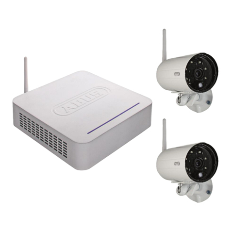
Abus DTS3218 User manual

Abus

Abus DTS3218 User manual

Abus TVAC15000C User manual

Abus

Abus TVAC15000C User manual

Abus TVAC16000B User manual

Abus

Abus TVAC16000B User manual

Abus Outdoor motion detector PIR User manual

Abus

Abus Outdoor motion detector PIR User manual

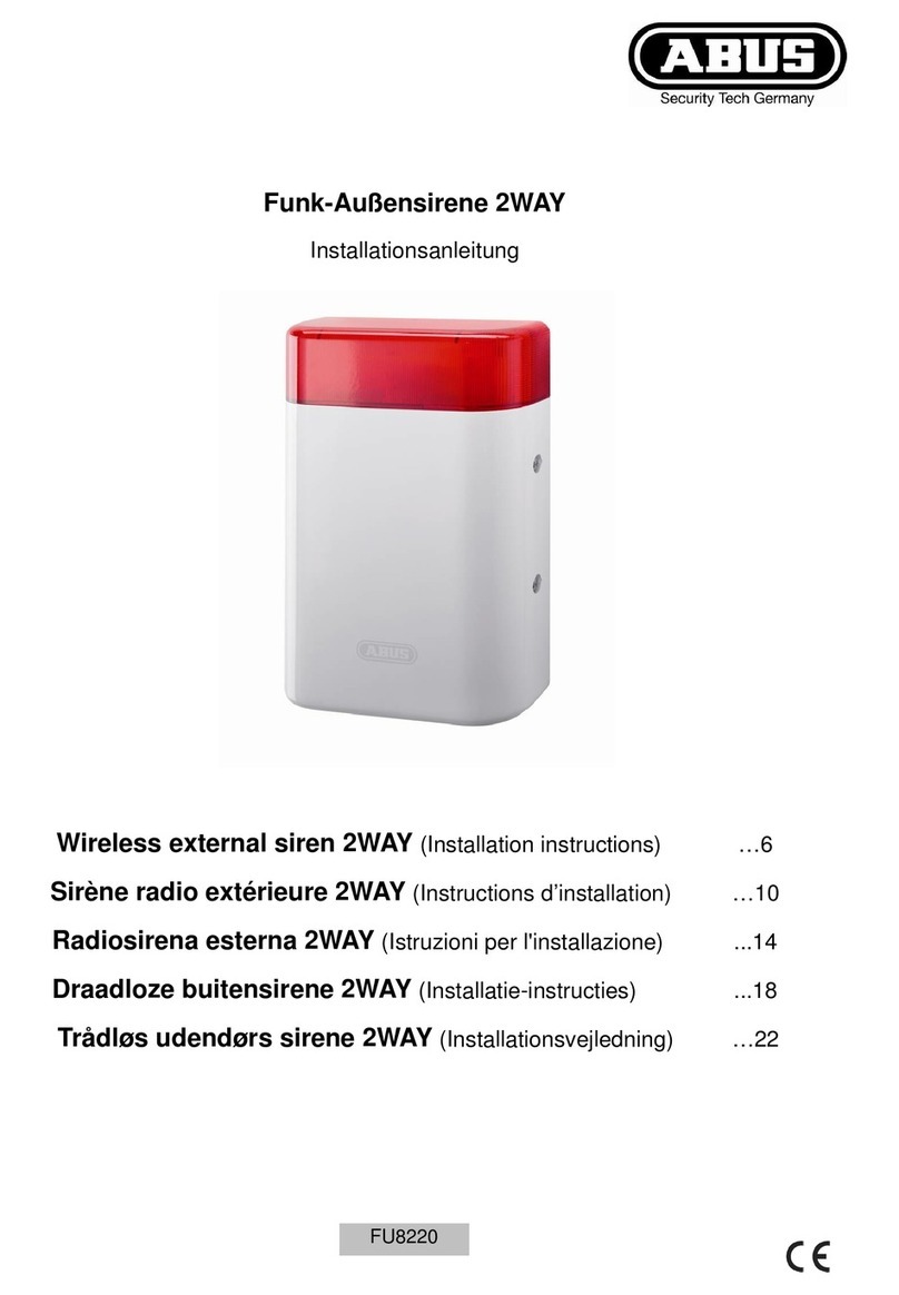
Abus WIRELESS ALARM SYSTEM User manual

Abus

Abus WIRELESS ALARM SYSTEM User manual

Abus TVAC14000A User manual

Abus

Abus TVAC14000A User manual

Abus Terxon MX User manual

Abus

Abus Terxon MX User manual

Abus TVAC18000A User manual

Abus

Abus TVAC18000A User manual

Abus CASA10010 User manual

Abus

Abus CASA10010 User manual

Abus FUSG35000A User manual

Abus

Abus FUSG35000A User manual

Abus TVAC15000 User manual

Abus

Abus TVAC15000 User manual

Abus PPIC35520 User manual

Abus

Abus PPIC35520 User manual

Abus WIRELESS ALARM SYSTEM User manual

Abus

Abus WIRELESS ALARM SYSTEM User manual

Abus FUSG30000 User manual

Abus

Abus FUSG30000 User manual

Abus SECVEST User guide

Abus

Abus SECVEST User guide

Abus TVAC26030 User manual

Abus

Abus TVAC26030 User manual

Abus PPDF16000 User manual

Abus

Abus PPDF16000 User manual

Abus TVAC18000B User manual

Abus

Abus TVAC18000B User manual

Abus TVAC16000B User manual

Abus

Abus TVAC16000B User manual

Abus SG1800 User manual

Abus

Abus SG1800 User manual

Abus SECVEST User manual

Abus

Abus SECVEST User manual

Abus KeyGarage 787 Manual

Abus

Abus KeyGarage 787 Manual

Abus PPDF18000 User manual

Abus

Abus PPDF18000 User manual

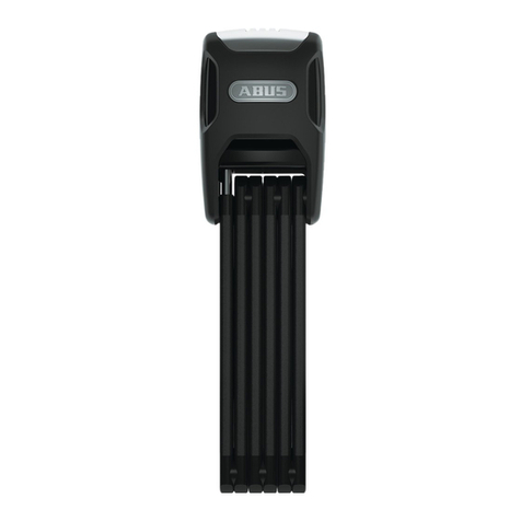
Abus Bordo 6000 Alarm User manual

Abus

Abus Bordo 6000 Alarm User manual

Popular Security System manuals by other brands

Polon-Alfa 4000 Installation and maintenance manual

Polon-Alfa

Polon-Alfa 4000 Installation and maintenance manual

Nexcom NViS 14162 Series user manual

Nexcom

Nexcom NViS 14162 Series user manual

Eminent EM8670 Quick install

Eminent

Eminent EM8670 Quick install

urmet domus alpha 1060 INSTALLATION AND USE BOOKLET

urmet domus

urmet domus alpha 1060 INSTALLATION AND USE BOOKLET

SmartPool YardGuard YG03 manual

SmartPool

SmartPool YardGuard YG03 manual

DSC PC5964 Mounting instructions

DSC

DSC PC5964 Mounting instructions

Secure USAB-1 operating instructions

Secure

Secure USAB-1 operating instructions

B&B 480 SERIES Operation & maintenance manual

B&B

B&B 480 SERIES Operation & maintenance manual

ADEMCO VISTA-20P Series Installation and setup guide

ADEMCO

ADEMCO VISTA-20P Series Installation and setup guide

Inner Range Concept 2000 user manual

Inner Range

Inner Range Concept 2000 user manual

Johnson Controls PENN Connected PC10 Install and Commissioning Guide

Johnson Controls

Johnson Controls PENN Connected PC10 Install and Commissioning Guide

Aeotec Siren Gen5 quick start guide

Aeotec

Aeotec Siren Gen5 quick start guide

Swann SW-P-MC2 Specifications

Swann

Swann SW-P-MC2 Specifications

Ecolink Siren+Chime user manual

Ecolink

Ecolink Siren+Chime user manual

EDM Solution 6+6 Wireless-AE installation manual

EDM

EDM Solution 6+6 Wireless-AE installation manual

Siren LED GSM operating manual

Siren

Siren LED GSM operating manual

Detection Systems 7090i Installation and programming manual

Detection Systems

Detection Systems 7090i Installation and programming manual

FRIEDLAND MA10 Installation and operating instructions

FRIEDLAND

FRIEDLAND MA10 Installation and operating instructions

manuals.online logo
manuals.online logoBrands
  • About & Mission
  • Contact us
  • Privacy Policy
  • Terms and Conditions

Copyright 2025 Manuals.Online. All Rights Reserved.

QUICK GUIDE
ABUS Security Center
GmbH & Co. KG
Linker Kreuthweg 5
86444 A ing
Germany, abus.com
PLSP90000
Nexello Sicherheitssystem, inkl. Akku und Z-Wave Modul
Nexello Securitysystem, with battery and Z-Wave RF-Module
Overview
Beschreibung
1. Wi / Bluetooth Antenna
2. USB Port 1
3. Slot for WLX Pro Module
4. Mainboard
5. Slot for Z-Wave Module
6. Sound Module
7. Tamperswitch front
8. Loudspeaker
9. Tamperswitch rear
10. Battery
Preparation
Vorbereitung
1 2
• Registrierung im Portal: https://Nexello-pilot.abus.com (Internetzugang erforderlich).
• Die Registrierung ist Grundvoraussetzung für die Installation & Konguration Ihrer Nexello.
Nach erfolgter Registrierung werden Ihre Daten von uns geprü und freigegeben.
• Pls. register at https://nexello-pilot.abus.com (Internet connection required).
• Registration is mandatory for installation & conguration of your Nexello System.
Upon successful registration, your data will be checked and conrmed by ABUS.
Die ausführliche Bedienungsanleitung und technische Daten nden Sie auf unserer Webseite.
Vous trouverez le manuel d’utilisateur détaillé et les données techniques sur notre site Internet.
De gedetailleerde gebruikershandleiding en technische gegevens vindt u op onze website.
Istruzioni d‘uso dettagliate e dati tecnici sono disponibili sul nostro sito web.
A full instruction manual and technical data can be found on our website.
www.abus.com/
product/PLSP90000
De detaljerede betjeningsvejledningen og tekniske data ndes i på vores hjemmeside.
Szczegółowa instrukcja obsługi oraz dane techniczne znajdują na naszej stronie internetowej.
Las instrucciones de uso detalladas y los datos técnicos se encuentran en nuestra página web.
Den detaljerade bruksanvisningen och tekniska data nns i på vår hemsida.
Ö nungswerkzeug /
Opening Tool
Innenabdeckung /
Inner cover
Wandhalterung /
Wall mount
Benötigtes Zubehör •
Required accessories
Lieferumfang • Scope of delivery
1×
4×
2×
1×
Quick
Guide
1×
1× 1×
1×
1×
T10 – Torx
Schraubendreher,
sowie Kreuz/Schlitz-
Schraubendreher
1×
• Befestigen Sie die Halterung mit den beiliegenden Schrauben und Dübeln an der Wand.
• Planen Sie ausreichenden Abstand für die Montage ein. Sie benötigen ca. 180mm
(gemessen vom horizontalen Haltesteg) um die Zentrale in den Wandanker
zu schieben. Sowie 155mm (zu beiden Seiten).
• Fix the wall mount using the screws and dowels provided.
• Provide sucient space for installation. approx. 180mm (measured from the horizontal
retaining bar) to push the Panel onto the wall mount, as well as 155 mm. (on both sides)
Fix the wall
mount
Wandanker
montieren
180 mm frei
nach oben
155 mm zu
den Seiten
Technische und farbliche Änderungen vorbehalten.
Für Irrtümer und Druckfehler keine Ha ung ©ASC2020
Subject to technical modi cations and colour changes.
No liability is assumed for mistakes or printing errors. ©ASC2020
1. WLAN / Bluetooth Antenne
2. USB Steckplatz 1
3. Steckplatz für WLX Pro Modul
4. Hauptplatine
5. Steckplatz für Z-Wave Modul
6. Audiomodul
7. Sabotageschalter Deckel
8. Lautsprecher
9. Sabotageschalter Wand
10. Akku
11. Schraubendurchführung zur Fixierung am Wandanker
12. Ladeelektronik für Notstromversorgung
13. LED für Statusanzeige
14. Netzwerkanschluss
15. USB Steckplatz 2 + 3
16. Micro SD Card Slot
17. Reset-Taster
18. Zugentlastungen
19. Stromversorgung DC Buchse
20. Schraubdome zur Fixierung der Abdeckung
1
8
9
3
18
11
7
2
5
10 12
13
14
15
16
17
20
4
6
19
11. Screw channel for  xing to wall mount
12. Power-board for secondary power supply
13. Status LED
14. RJ45 LAN Port
15. USB Port 2 + 3
16. Micro SD Card Slot
17. Reset-Button
18. Strain relief
19. 5V DC Port
20. Screw dome for  xation of inner cover
1
2
Connect LAN/
DC-cable
LAN/DC-Kabel
anschließen
3
6
9
7
10
Restart and
System reset
Neustart &
System-Reset
5
8
• Schieben Sie die Önungs-Tools in die Auslässe, um den Deckel zu lösen.
• Lösen Sie die Schraube (Torx-T10) und schieben die Innenabdeckung nach oben heraus.
• Put the opening tools into the outlets to release the Lid.
• Loosen the screw (Torx-T10) and slide the inner cover upwards.
Open the
housing
Gehäuse
Ö  n e n
Deckel schließen
& System ist
einsatzbereit
Ersteinrichtung
per App oder
Web-Browser
durchführen
• Stecken Sie das Netzteil in eine Steckdose sowie das Netzwerkkabel an den Router.
•
Führen Sie das Netzwerk-Kabel sowie das Netzteil-Kabel durch die Önung im Gehäuseboden,
wickeln diese 1x um die Zugentlastung u. schließen diese an der (1) LAN bzw. (2) DC-Buchse an
.
• Plug the Power adaptor to an outlet and the network cable to the router.
• Insert the LAN-cable + DC-cable through the opening in the bottom of the housing. Wrap
them one time around the strain relief and connect them to the LAN Port (1) and DC Port (2).
• Schließen Sie das Akku-Anschlusskabel an die Ladeelektronik an. (1)
• ERST JETZT: Schließen Sie das Powerkabel an die Ladeelektronik an (2) –
die Nexello bootet (signalisiert durch weißes Blinken der LED).
•Wichtiger Hinweis: Falls Sie das System vorab kongurieren & erst danach beim
Kunden montieren, trennen Sie bitte bei der Außerbetriebnahme zunächst das
Powerkabel (2) und danach das Akku-Anschlusskabel (1) von der Ladeelektronik.
• Connect the Battery-cable (1) to the power-board.
• Only now: connect the power-cable to the power-board (2)
The system will then boot. (indicated by white ashing of Status-LED).
• Important note: In case you congure the system rst and decommission it
before installation on site, pls rst disconnect the power-cable (2) and then
the battery-cable (1) from the power-board.
• Schieben Sie den Gehäuseboden bis zum Anschlagpunkt auf den Wandanker.
• Hinweis: Achten Sie darauf, dass der Wand-Abriss-Kontakt geschlossen ist. (Klick-Geräusch)
• Fixieren Sie den Gehäuseboden anschließend an der Wandhalterung.
• Hinweis: Schraube bis zum Anschlagpunkt drehen – erst dann ist
diese mit dem Wandanker verbunden!
• Slide the lower housing onto the wall mount as far as it will go.
• Remark: Pls. pay attention, that the rear tamperswitch is closed. (click noise)
• Fix the lower housing onto the wall mount.
• Remark: turn the screw as far as it will go – only then it will be xed to the wall mount.
• Schließen Sie den Deckel. Bitte drücken Sie den Deckel in Höhe
der Auslässe sodass der Önungs-Mechanismuss hörbar einrastet.
• Die Zentrale ist betriebsbereit, wenn die LED grün leuchtet
• Close the lid. Please press the lid in height of the outlets so
that the opening mechanism audibly clicks into place.
• The Panel is ready for operation once the Status LED lights green.
• Installieren & Starten Sie die App „Nexello“ von „ABUS Security Center“.
Sie nden die App im Google-Playstore bzw. IOS App Store.
• Alternative Inbetriebnahme per Webbrowser möglich.
• Halten Sie ihren Installateur-QR-Code zur Installation des Systems bereit.
Der Code wird Ihnen nach erfolgreicher Registrierung im Nexello-Pilot Portal mitgeteilt.
• Für die erste Inbetriebnahme ist es erforderlich, dass die Zentrale mit dem Internet
verbunden ist.
• Install & start the App „Nexello” from “ABUS Security Center”.
You nd the App on the Google-Playstore or IOS App Store.
• Alternative installation via Web-Browser possible.
• Have your installer QR-Code ready to install the system.
You will receive the code aer your registration on Nexello-pilot.abus.com has been veried.
• The initial setup requires that the Nexello system is connected to the internet.
• Setzen Sie das System zunächst in den Wartungs-Modus, um eine Alarmauslösung
zu vermeiden (Bedienungsanleitung) und önen danach den Deckel.
• Drücken Sie die Reset-Taste 1x kurz für Neustart.
• Halten Sie die Reset-Taste 10 sek. lang gedrückt um das Gerät auf
Werkseinstellungen zurückzusetzen. (So-Reset)
• Hinweis: Ein vollständiger Reset inkl. Entfernung des Systems aus Ihrem
Nexello-Pilot Account ist nur per App/Webbrowser möglich. (Bedienungsanleitung)
• First put the system into maintenance mode to avoid triggering
an alarm (instruction manual) and open the cover aerwards.
• Short-press the reset button one time to restart the system.
• Or keep the reset button pressed for 10 seconds to fully reset the system. (so-reset)
• Remark: An entire reset (incl. removal of the system from your Nexello-pilot
account can only be done via App/Webbrowser. (instruction manual)
• Stecken Sie das Z-Wave Funkmodul auf den vorgesehenen Steckplatz.
• Stecken Sie das WLX Pro Control Modul auf den vorgesehenen Steckplatz. (Optional)
• Hinweis: Bitte Platzierung wie abgebildet beachten!
•Hinweis: Bitte achten Sie darauf, dass das Funkmodul
vollständig d.h. mit allen 6 Pins aufgesteckt ist.
• Plug the Z-Wave module into the designated slot.
• Plug the WLX Pro Control Module into the designated slot. (optional)
• Remark: Pls note the placement as shown!
• Remark: Pls. make sure that the RF-Module is completely plugged. (with all 6 pins)
Plug in
RF-Modules
Funk-Module
anstecken
Akku u.
Powerkabel
anstecken
4
WLX Pro
Z-Wave
1
2
• Schieben Sie die Innenabdeckung bis zu den Rastpunkten auf und befestigen die Schraube.
• Slide the inner cover up to the locking points and fasten the screw.
Close the
inner cover
Innenab-
deckung
schließen
Fix the Panel to
the wall mount
Zentrale an
Wandanker
schrauben
Connect the
battery and
power-cable
Close the lid &
System is ready
for operation
Initial setup
via App or
Web-Browser