WARNING: Failure to read and follow these installation instructions and safety precautions could result in personal injury, equipment damage,
shortened service life or unsatisfactory equipment performance. All information in this document is vital to the proper installation and operation
of the equipment. It is important that all personnel who will be coming in contact with this product thoroughly read and understand this manual.
INSTRUCTION
MANUAL
©2020 VIBCO, Inc. IM_H_B-H_05020
B&H SERIES
HYDRAULIC
5VIBRATOR PLACEMENT 6MOUNTING HARDWARE
7STITCH WELD MOUNTING
1START 2MOUNTING CHECKLIST
qDetermine vibrator placement on equipment (box 5).
qDetermine length of channel iron and style of mounting plate (box 4).
qSTITCH weld mounting plate to channel iron (box 7).
qSTITCH weld channel iron & mounting plate combo to bin (box 7).
qAttach vibrator to mounting plate. Check mounting plate for warping
and shim if necessary. DO NOT OVER TIGHTEN THE BOLTS (box 8).
qInstall safety chain or cable (box 9).
qConnect Hydraulics for vibrator using the ASME and
SAE Standards (box 10).
qFILL OUT WARRANTY CARD & MAIL TO VIBCO!!!!
ADDITIONAL DETAILS AVAILABLE ONLINE AT www.vibco.com
3TECHNICAL DATA
DO NOT
EXCEED
MAXIMUM
FLOW
RATE
FOR ANY
MODEL
4PLATE & CHANNEL SELECTION
Bin Wall
Thickness
Factor
B
1/8"
(10 ga.)
or less
6
1/8" - 1/4" 5
1/4" - 3/8" 4
3/8" - 1/2" 3
1/2" & up 2
Factor
A + B
Use
Channel Iron
Length
11 N/A
10 6 - 8 FT.
(80 - 90%)
95 - 7 FT.
(70 -80%)
84 - 6 FT.
(60 - 70%)
73 - 5 FT.
(50 - 60%)
62 - 4 FT.
(50 - 60%)
51 - 2 FT.
(50 - 60%)
4 N/A
NOTE:
1. Longer channel iron will not affect vibrator performance, but
total channel length should not exceed length of bin wall.
2. Percentages shown indicate % of bin wall height your channel iron
should be for shorter bins.
3. To match your vibrator on chart above, model number sufxes
generally correspond to pounds of force generated. See chart (box 3).
MOUNTING PLATES, CHANNEL IRON & ACCESSORIES AVAILABLE FROM VIBCO OR LOCAL DEALER
For coarse materials: mount
vibrator 1/3 of the distance
from the discharge opening to
the top of the sloped portion of
the bin.
For ne materials: mount
vibrator 1/4 of the distance
from the discharge to the top of
the sloped portion of the bin.
FOR ALTERNATE MOUNTS: refer to full detail instruction manual online
at www.vibco.com or call 800-633-0032
A MOUNTING PLATE MUST BE USED
to ensure proper stability for the vibrator.
Always start & stop welds 1 in. from ends to
prevent heat
concentration.
Then weld 2 to
3 inches, skip
1 to 2 inches
and repeat
until the plate
is securely
mounted.
NO! YES!
MOUNTING PLATE MUST BE MOUNTED
PARALLEL TO CHANNEL IRON, NOT
PERPENDICULAR. OTHERWISE, IT WILL CAUSE
FLEXING & DAMAGE THE UNIT OR EQUIPMENT
IT IS MOUNTED TO.
STITCH
WELDS
SHOULD
BE 3” - 6”
LONG
LEAVING
3” (7.5cm)
BETWEEN
EACH
WELD
STITCH WELDS SHOULD
START & STOP 1” (2.5cm)
FROM BOTH ENDS OF
CHANNEL TO PREVENT
CRACKING
DO NOT MOUNT
VIBRATOR DIRECTLY TO
SURFACE OF THE BIN !!!
Always use mounting plate &
channel iron
Be sure you have selected the
proper length of channel using the
tables above (SECTION 4).
Improper mounting can
result in failure of
unit or damage
to equipment.
8BOLTING PROCEDURE
Angle Iron Channel Iron
DAMAGE TO THE BIN OR THE
VIBRATOR WILL OCCUR IF NOT
MOUNTED SECURELY!
For other bolt grades,
please consult VIBCO.
GRADE 5
BOLT SIZE
MAX
TORQUE
ft-lbs
1/4" 9
5/16" 18
3/8" 32
1/2" 78
5/8" 160
3/4" 260
1" 580
1-1/4" 1105
Check mounting bolts every 200 hours.
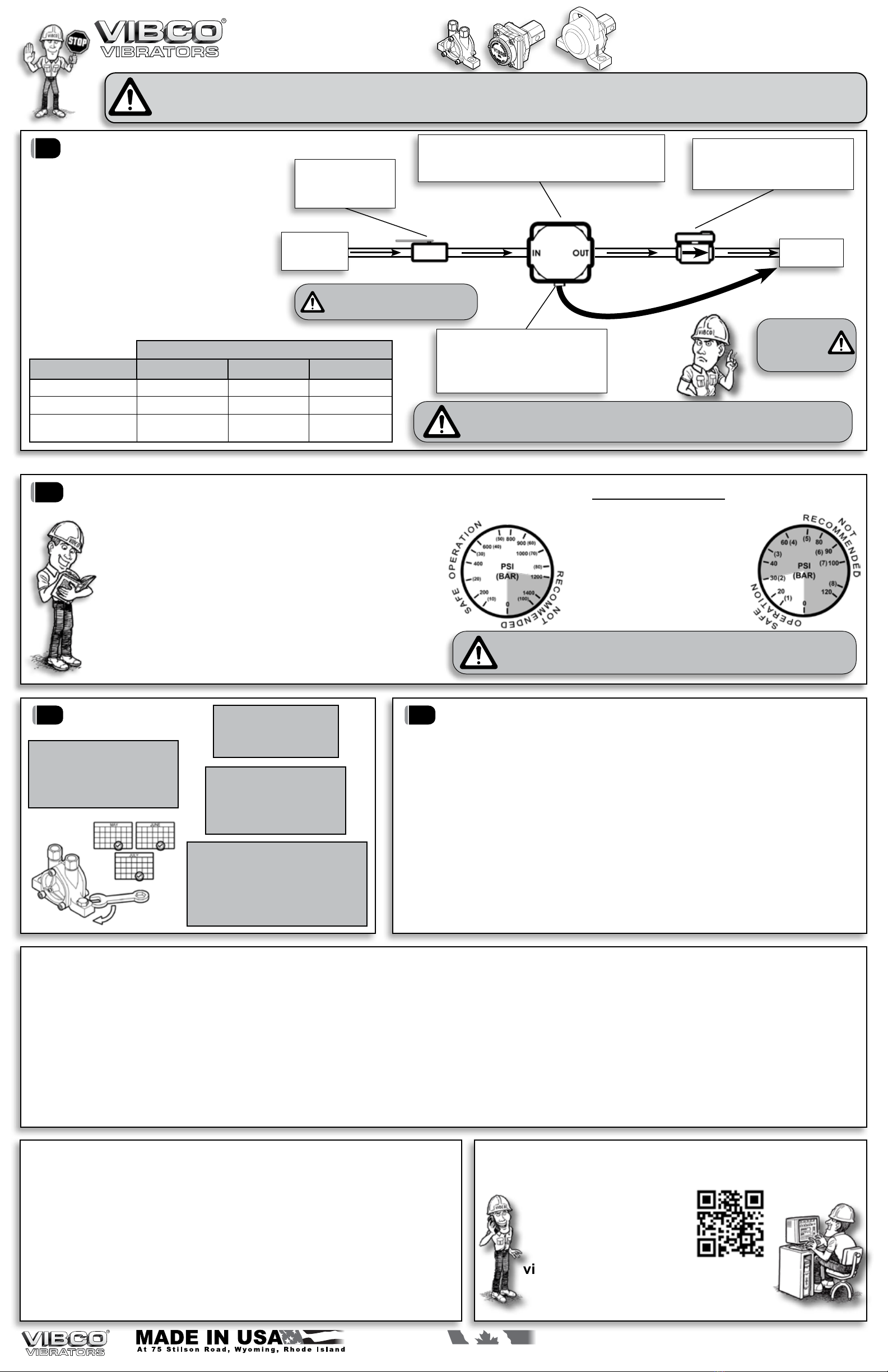
10 HYDRAULIC CONNECTION B-SERIES
1. Coat all ttings with sealing compound
and secure hydraulic hoses to inlet
& outlet sides of motor as marked by
directional arrows.
2. Hook up ball valve on inlet side and
check valve on outlet side to reservoir.
3. Check & tighten all ttings &
connections before test running
vibrator.
4. Hydraulic system MUST have a
ltration system & oil is industrial
petroleum-based oil, SAE 10 to 30,
with wear oxidation and foaming
inhibitors, and a viscosity of 200 SSU.
DO NOT OVER
TIGHTEN
HYDRAULIC
HOSE FITTINGS
MAXIMUM
OIL TEMP.
150°F (65°C)
THREAD SIZE
MODEL
NUMBER INLET OUTLET
B-190 3/8” - NPT 3/8” - NPT
B-250 1/2” - NPT 1/2” - NPT
B-320 1/2” - NPT 1/2” - NPT
FROM
HYDRAULIC
PUMP
FLOW
CONTROL VALVE
MUST be located on
inlet side of motor
TO
RESERVOIR
ATTENTION: WHEN HOOKING UP MULTIPLE UNITS YOU MUST
SUPPLY INDEPENDENT HYDRAULIC LINES. UNITS WILL NOT RUN TO
FULL SPECIFICATIONS & MAY FAIL WHEN INSTALLED IN SEQUENCE.
CHECK VALVE
MUST be located 16” - 24” (400mm-600mm)
away from motor on outlet line side
RETURN LINE
Return line must be connected back to the oil
reservoir and NOT to any line under pressure
STANDARD STUDDED
2 BOLT
4 BOLT
THANK YOU FOR CHOOSING
A VIBCO VIBRATOR!
DON’T FORGET
TO MAIL IN YOUR
WARRANTY CARD!
Hydraulic
Models
Weight
600 PSI (41.4 Bar) 800 PSI (55.2 Bar) 1000 PSI (69 Bar)
Vibration
/min.
Gallon
/min.
Centrifugal
Force
Vibration
/min.
Gallon
/min.
Centrifugal
Force
Vibration
/min.
Gallon
/min.
Centrifugal
Force
lbs. kg. VPM GPM lbs. Newtons
VPM GPM
lbs. Newtons
VPM GPM
lbs. Newtons
B-190
1.0 0.45 4,600 4.5 190 890 6,100 4.8 330 80 7,400 6.5 286 1,272
B-250
2.0 0.91 4,200 4.5 280 1,245 5,000 4.5 400 1,765 5,800 6.5 535 2,375
B-320
3.5 1.60 3,700 5.0 300 1,340 4,500 6.0 445 1,980 5,300 7.0 615 2,745
Hyd.Models Weight Avg. Vibration/min. Gallon/min. Centrifugal Force Sound*
lbs. kg. PSI
VPM GPM
lbs. Newtons
dB
HF-800
37 17.0 600 5,000 3.2 1,300 5,785 72
HF-1200
38 17.4 800 4,500 2.9 1,900 8,450 74
HF-1500
39 17.7 900 4,000 2.6 2,000 8,900 76
HF-HC-3500
51 23.0 1,200 3,500 2.4 3,500 15,570 80
HL-3000
39 17.7 1,000 5,000 3.2 3,400 15,125 76
HLF-700
14 6.5 900 9,000 2.8 700 3,115 72
HLF-1300
20 9.0 1,000 9,000 2.8 1,300 5,785 72
HLF-1750
30 14.0 1,000 5,000 2.6 2,300 10,230 72
HLF-3500
35 16.0 1,200 4,000 2.5 3,500 15,570 72
HLF-5000
41 18.6 1,500 4,000 2.5 4,500 20,020 72
* Decibel from A-scale at 1 meter & avg. PSI (or max. listed value)
Dataobtainedonlaboratorytestblock•Datasubjecttodesignchanges
Frequency&forcewilldecreaseonlessrigidmount•Maxpressure3,000PSI
Vibrator
Force
in lbs
Mounting
Plate
Thickness
Channel Iron Size Factor
A
101 - 500 1/4" - 3/8" 3" x 4.1 lbs.
3" x 5 lbs. 2
501- 1200 1/2" 4" x 5.4 lbs.
4" x 7.5 lbs. 3
1201-3000 5/8" 6" x 8.2 lbs. / 6" x 10.5 lbs. 4
3001-5000 3/4" - 1" 6" x 8.2 lbs. / 6" x 10.5 lbs.
8" x 8.5 lbs. / 8" x 11.5 lbs. 5
9R
ESTRAINT
ALWAYS
INSTALL
SAFETY
CABLE or
CHAIN
Mount one end to the
vibrator and the other to
the hopper or bin
above the vibrator
NEVER ATTACH TO
THE MOUNTING
PLATE!