800-633-0032
2215 Dunwin Dr., Mississauga, Ont. L5L 1X1
WARNING: Failure to read and follow these installation instructions and safety precautions could result in personal injury, equipment damage,
shortened service life or unsatisfactory equipment performance. All information in this document is vital to the proper installation and operation
of the equipment. It is important that all personnel who will be coming in contact with this product thoroughly read and understand this manual.
INSTRUCTION
MANUAL
©2018 VIBCO, Inc. MA-CC-29718
CC TURBINE
VIBRATORS
11 OPERATING SPECIFICATIONS
12 TROUBLE SHOOTING
Warranty
All warranty claims must be submitted to VIBCO for approval prior to any
repairs being done. Failure to do so will void any and all warranty coverage.
All repairs will be done at the VIBCO factory.
Errors, Shortages & Complaints
Complaints concerning goods received or errors should be made at once.
Claims must be made within ve days after receipt of goods. Clerical errors
are subject to correction. Damage during shipping must be reported to the
carrier, not VIBCO.
Returning Parts
Parts should not be returned to VIBCO without prior authorization. Call VIBCO’s
customer service department at 800-633-0032 (800-465-9709 in Canada) for
a Return Goods Authorization (RGA) number. A return authorization will be
emailed or faxed to you. Use this as your packing slip. Return shipping must
be prepaid. Material returned may be subject to a 10% restocking fee. All
returned shipments should clearly display your name, address and original
invoice number to ensure proper credit.
YOU CAN FIND
ADDITIONAL DETAILS &
INSTRUCTIONS ONLINE AT
www.vibco.com
Look for the
Support link on the homepage
Maximum Air
Pressure
For continuous
use, operating
pressure should
not exceed 80 psi
unless specially
constructed from
the factory.
Safe Operation for
Intermittent Duty
Not Recommended
Maximum
Temperature
The operating
temperature of the
vibrator should not
exceed 200°F (93°C).
High temperature
units are available
from factory.
Safe Operation for
Continuous Duty
Not Recommended
200°F 93°C
1. Check for dirt in the airline or inlet opening.
2. Check air line back to compressor for holes or
disconnections.
1. Double check the size of your airline - is it large
enough to give you the correct cubic feet per
minute (CFM) and correct air pressure
(minimum required = 20 PSI).
2. Bearings require a short “break-in” period to run
at optimum VPM stated in catalog.
VIBRATOR WON’T START?
VIBRATOR WON’T GET UP TO SPEED?
Orders for custom equipment built to customer’s specications are not
returnable.
Product Changes
VIBCO reserves the right to make changes in pattern, design or materials when
deemed necessary, without prior notice or obligation to make corresponding
changes in previous models. To be sure of exact mounting dimensions, it is
recommended that you obtain a certied dimensional drawing from the factory.
Ordering Spare Parts
Parts can be ordered through authorized distributors or from VIBCO’s Spare
Parts Department. The following data should be provided when placing your
spare parts order:
q Model of unit from the foot of the vibrator housing
q Reference number, part number, description and quantity required from
spare parts list
q Shipping instructions: Specify shipping point and method of shipping.
800-633-0032 for Mounting Plates & Brackets, Spare & Replacement Parts
and
24/7 Technical Support
For custom mounting applications or any other questions:
800-633-0032 or
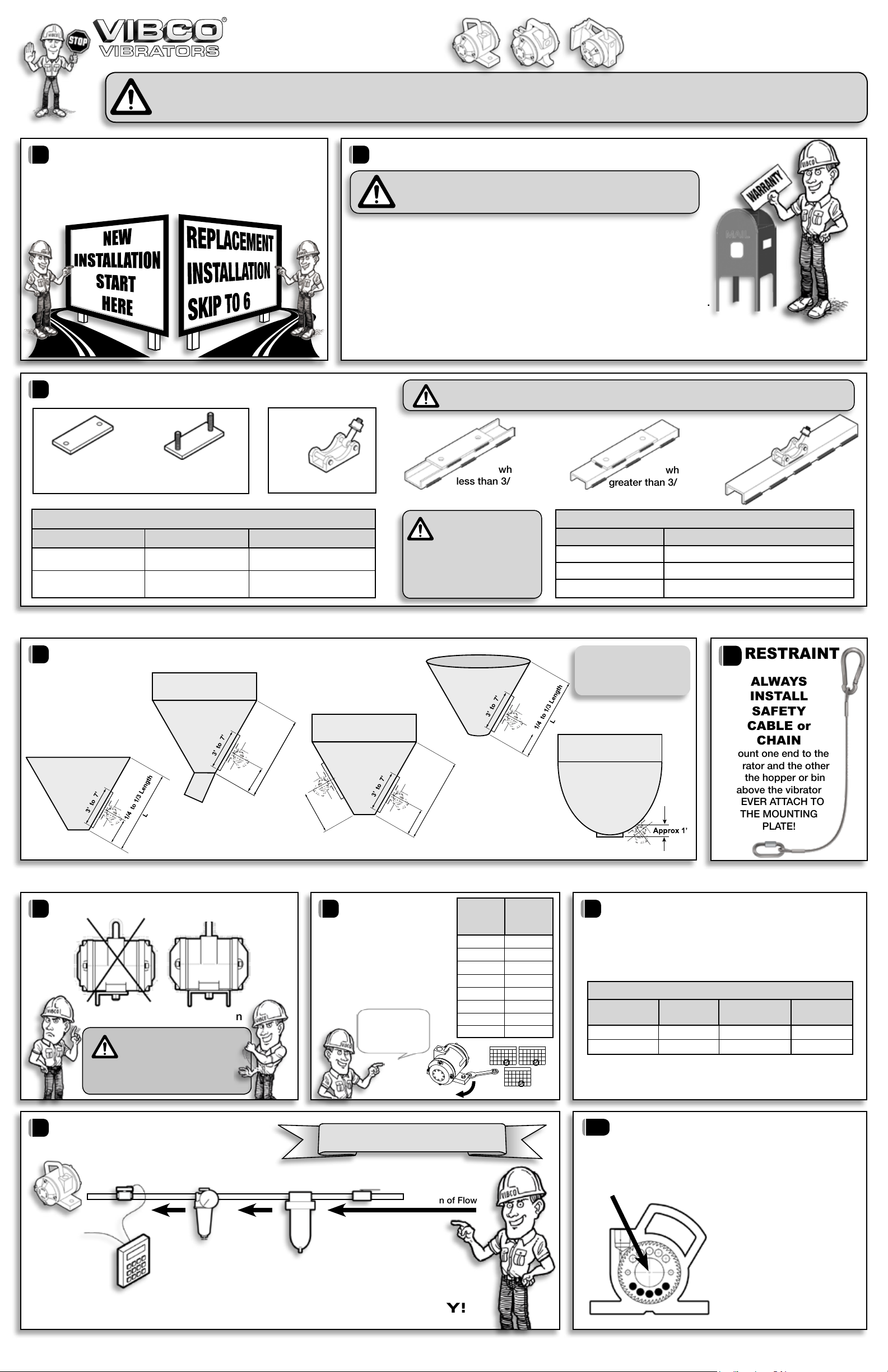
VIBCO turbine
vibrators
function without
maintenance.
They require no lubrication in the
air line. It is advisable to put an
in-line air-cleaner to prevent dust
and dirt from going through the unit
and clogging the muer. No other
maintenance is required.
REPAIR KITS
Repair kits are available through VIBCO. Instructions
are included with the kit and available online at
www.vibco.com. Replacing parts not issued by
VIBCO will void warranty. Any further questions or
concerns please call the factory 800-633-0032.
The repair kit includes everything
you need to make your vibrator
run like new.
ADDITIONAL DETAILS AVAILABLE ONLINE AT www.vibco.com
Repair Kits Include: Stover Nut, Inside Cover with
Keyway, Seal Ring, CR Seal, Bearings,
Turbine Wheels, Key & Shaft.
DON’T FORGET TO RETURN YOUR WARRANTY CARD TO VIBCO!