Vicon Roughneck AI V2360W-12-1 User manual

Quick Guide
Roughneck AI V2360W-12-1
Outdoor Panoramic Camera
XX318-70-06
Cybersecurity Notification: All network connected devices should use best practices for
accessing the device. To that end, these network cameras do not have a default password. A user defined
password with minimum password strength requirements must be set to access the device. See page 13of
this Quick Guide for set-up instructions.
Be sure to check Vicon’s website to be see if you have the most up-to-date camera firmware.
Vicon Industries Inc. does not warrant that the functions contained in this equipment will
meet your requirements or that the operation will be entirely error free or perform precisely as
described in the documentation. This system has not been designed to be used in
life-critical situations and must not be used for this purpose.
Document Number: 8009-8318-70-06 Product specifications subject to change without notice.
Issued: 2/2023 Copyright © 2023 Vicon Industries Inc. All rights reserved.
Vicon Industries Inc.
Tel: 631-952-2288) Fax: 631-951-2288
Toll Free: 800-645-9116
24-Hour Technical Support: 800-34-VICON
(800-348-4266)
UK: 44/(0) 1489-566300
www.vicon-security.com

V2360W-12-1 Panoramic Fisheye | Quick Guide
1 -
Table of Contents
1Product Overview 4
1.1 Physical Characteristics 4
2Installation, Mounting and Connections 8
2.1 Package Contents 8
2.2 Installation 8
2.2.1 Checking Appearance 8
2.2.2 Mounting Camera 9
3Connection 12
3.1 Network 12
3.2 System Requirements 12
3.3 Connecting Process 13
3.3.1 Accessing the Camera 13
3.3.2 Connecting from a Computer 13
3.4 PRONTO Device Manager 14

V2360W-12-1 Panoramic Fisheye Series | Quick Guide
2 -
WARNING
This camera operates at 12 VDC/24 VAC/PoE+ (IEEE 802.3at Class 4).
Installation and service should be performed only by qualified and experienced technicians and comply
with all local codes and rules to maintain your warranty.
We are NOT liable of any damage arising either directly or indirectly from inappropriate installation which
is not depicted within this documentation.
To reduce the risk of fire or electric shock, do not expose the product to rain or moisture.
Wipe the camera with a dry soft cloth. For tough stains, slightly apply diluted neutral detergent and wipe
with a dry soft cloth.
Do not apply benzene or thinner to the camera, which may cause the surface to melt or lens fog.
Avoid aligning the lens with extremely bright objects (e.g., light fixtures) for long periods of time.
Although this camera is waterproof and suitable for both indoor and outdoor usages, do not immerse the
camera into water.
Avoid operating or storing the camera in the following locations:
Extremely humid, dusty, or hot/cold environments (recommended operating temperature:
-40°F to +122°F/-40°C to +50°C)
Close to sources of powerful radio or TV transmitters
Close to fluorescent lamps or objects with reflections
Under unstable or flickering light sources
Get Started
This quick guide is designed as a reference for installation of the camera. For additional information on the
camera’s features, functions, and detailed explanation of the web interface controls, refer to User’s Manual for
details. Please read this quick guide thoroughly and save it for future use before attempting to install the
camera. From this guide you will get:
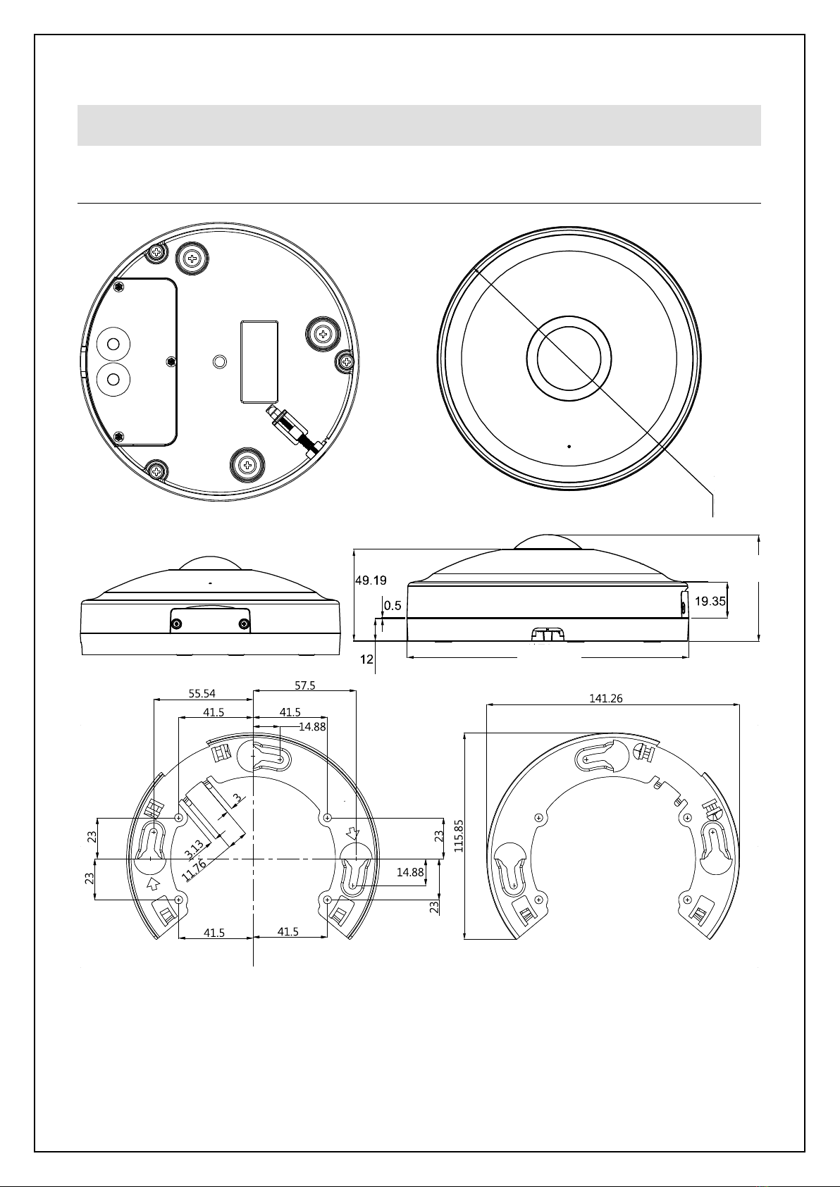
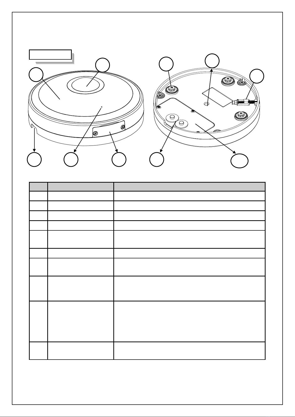
Product Overview: The physical parts, features and dimensions of the camera.
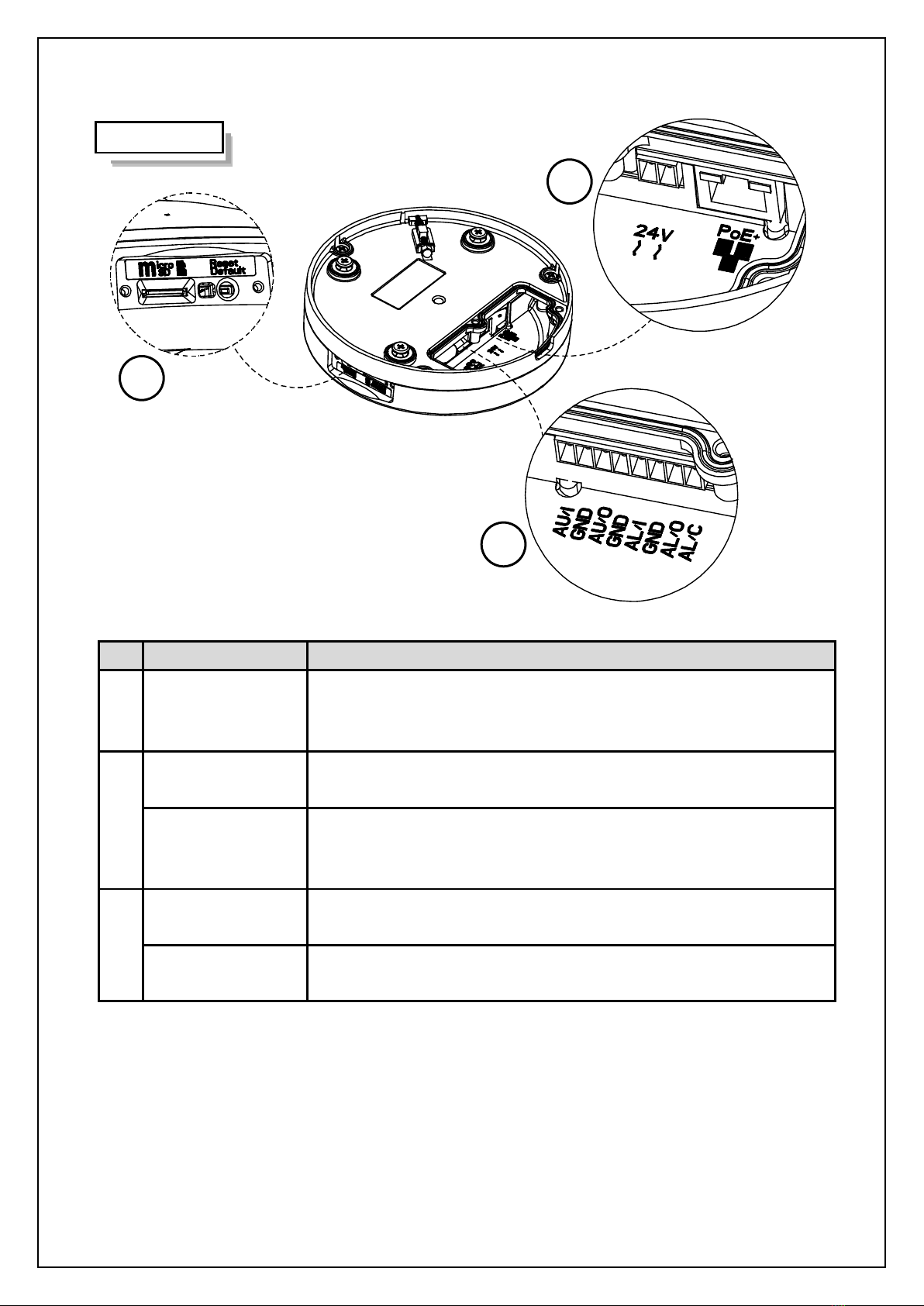
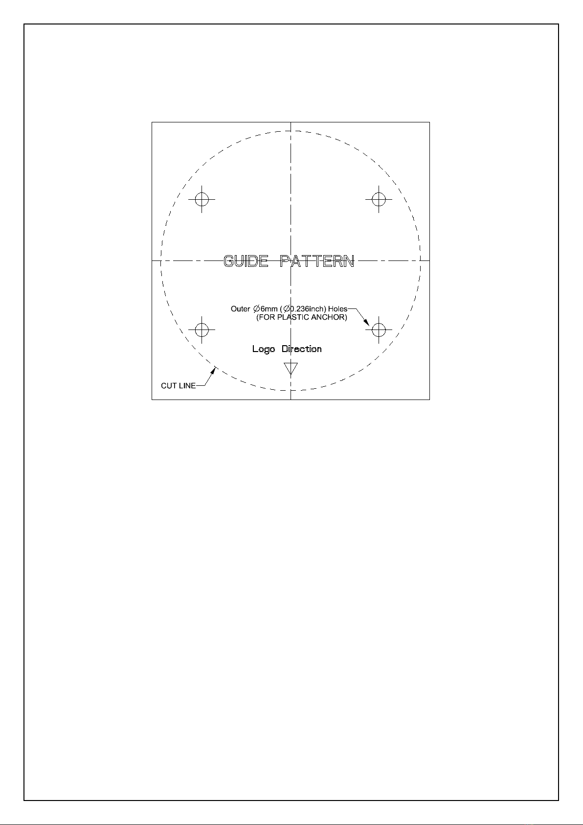
Installation and Connection: The instructions on installation and wires connection for the camera.
WEEE (Waste Electrical and Electronic Equipment). Correct disposal of this product
(applicable in the European Union and other European countries with separate collection
systems). This product should be disposed of, at the end of its useful life, as per applicable
local laws, regulations, and procedures.

V2360W-12-1 Panoramic Fisheye | Quick Guide
3 -
FCC Compliance Statement
Information to the user: This unit has been tested and found to comply with the limits for a Class
B digital device pursuant to Part 15 of the FCC Rules. Operation is subject to the following two
conditions: (1) this device may not cause harmful interference, and (2) this device must accept
any interference received, including interference that may cause undesired operation. These
limits are designed to provide reasonable protection against harmful interference in a residential installation.
This unit generates, uses, and can radiate radio frequency energy and, if not installed and used in accordance
with the manual, may cause harmful interference to radio communications. However, there is no guarantee
that interference will not occur in a particular installation.
If this unit does cause harmful interference to radio or television reception, which can be determined by
turning the unit off and on, the user is encouraged to try to correct the interference by one or more of the
following measures:
Reorient or relocate the receiving antenna.
Increase the separation between the unit and receiver.
Connect the unit to an outlet on a circuit different from that to which the receiver is connected.
Consult the dealer or an experienced radio/TV technician for help.
Caution Changes or modifications not expressly approved by the party responsible for compliance
could void the user’s authority to operate the unit.
CE Statement
Operation is subject to the following two conditions: (1) this device may not cause harmful
interference, and (2) this device must accept any interference received, including interference
that may cause undesired operation. The manufacturer declares that the unit supplied with this
guide is compliant with the essential protection requirements of EMC directive and General Product Safety
Directive GPSD conforming to requirements of standards EN55022 for emission, EN 50130-4 for immunity,
EN 300 and EN 328 for WIFI.
This product is IP67 rated for outdoor environments and IK10 rate for impact protection. The camera also
meets regulations required to be NDAA, GSA schedule and TAA approved.

V2360W-12-1 Panoramic Fisheye Series | Quick Guide
4 -
1Product Overview
1.1 Physical Characteristics
Figure 1 - 1: Physical Dimension
Ø2.8 (70)
Ø150 (5)
Ø5 (150)
56.99 (2.2)
Unit: mm (in.)

V2360W-12-1 Panoramic Fisheye | Quick Guide
5 -
Figure 1 - 2: Outer View Pictorial Index
No Name Description
1 Dome Cover The upper dome-shape cover provides protection
2 Lens The proprietary fisheye lens provides wide hemispheric view
3 Cabling Cutout The cutout hole for cables threading
4 Microphone Vent The hole for built-in microphone to receive audio input
5 Side Cap Loosen the 2 screws to open the side cap to access inner
interfaces for use.
6 Mounting Screws The 3 symmetrical screws designed for mounting with bracket
7 Mounting Thread Hole With the standard female thread 1/4-20, the hole is for attaching an
additional bracket (sold separately) for installation flexibility.
8 Security Lock
The proprietary security lock design ensures camera is mounted
securelyonto the bracket. Refer to the “Security Lock
Settlement” chapter for details on how to properly set up.
9 Waterproof Grommet
The specifically designed dual waterproof grommet (rubber plug)
allows multiple cables to thread through and provides waterproof
function at the same time. Prior to threading, pull the rubber plug
out. Seal the plug back to the position when no cable thread is in
use.
10 Rear Cap Loosen the 3 screws to open the rear cap to access the inner ports
and interfaces for further use.
Table 1 - 1: Outer View Pictorial Index Definition
4
3
5
1
2
6
10
9
7
Outer View
8

V2360W-12-1 Panoramic Fisheye Series | Quick Guide
6 -
Figure 1 - 3: Inner View Pictorial Index
No Interface Description
A DI/DO Terminal Ports
Connect to several external devices for audio and alarm input/output
functions, which can expand usability of camera for a variety of field
applications. Refer to Table 1 - 3 for details on port definitions.
B
RJ-45 PoE Port Insert an Ethernet cable that connects with internet device into the PoE
port for network connection and PoE (Power over Ethernet) capability.
24 VAC/12 VDC
Power Ports
To power on camera, connect 12 VDC or 24 VAC power source to the
corresponding 2-pin ports. Pay attention to polarity while cabling 12 VDC
power supply.
C
Reset & Default
Button
Press the button for less than 1 second to reboot the camera; pressing for
6 seconds will restore the camera to the factory default settings.
Micro SD Card Slot Insert a micro SDHC/SDXC card (customer supplied) into the slot for
recording and file storage
Table 1 - 2: Inner Interface Pictorial Index Definition
B
C
A
Inner View

V2360W-12-1 Panoramic Fisheye | Quick Guide
7 -
Name Port
AUDIO IN AU/I
GND
AUDIO OUT AU/O
GND
ALARM IN AL/I
GND
ALARM OUT
AL/O
AL/C
Table 1 - 3: I/O Port Definitions
Note Power supply terminal/adaptor for IO connectors and field wiring should comply with the
Class 2 Circuit standard for ensuring safety from electrical fires and providing acceptable
protection against electrical shock.
The Alarm out pin is a 30 VDC output signal with a maximum load of 1 A.
The Alarm in pin acts as a switch, which is either NO (Normal Open) or NC (Normal Closed).

V2360W-12-1 Panoramic Fisheye Series | Quick Guide
8 -
2Installation, Mounting and Connections
2.1 Package Contents
Check if all items listed below are included in the packing box.
Network Fisheye Camera * 1
Flat Bracket * 1
Safety Wire * 1
Plastic Anchors * 4
Tapping Screws * 4
Torx Wrench * 1
2-pin Terminal Block * 1
8-pin Terminal Block * 1
Printed Quick Guide * 1
Guide Pattern * 1
2.2 Installation
The following tools might help you complete the process of installation:
Drill
Screwdrivers
Wire Cutters
2.2.1 Checking Appearance
When unpacking, check to see if there is any visible damage to the appearance of the camera and its
accessories. The protective materials used for the packaging should protect the camera from most accidents
during shipment. Remove the protective materials from the camera after every item is properly checked in
accordance with the list in Package Contents.

V2360W-12-1 Panoramic Fisheye | Quick Guide
9 -
2.2.2 Mounting Camera
1. Attach the Guide Pattern to the mounting surface.
2. Drill 4 relative holes on a clean flat surface (ceiling or wall). Insert 4 plastic anchors into the drilled holes.
3. Attach the flat bracket onto the surface by fixing it tightly with the 4 screws (TP4).
Be sure to plug the drilled holes with the 4 plastic anchors prior to securing the bracket with the screws.
4. Open the rear cap by loosening the 3 screws. Connect the required cable threads as needed: 24 VAC/
12 VDC power cord to the 2-pin power terminal, Ethernet cable to the PoE port, and the additional audio
and alarm input/output cables to the 8-pin terminal block. Remove the rubber plug and insert the required
jacketed cables through the waterproof grommet to ensure proper IP66 water ingress protection; terminate
the cables. Note: do not slit or alter the grommet. If required, open the side cap by loosening the 2 screws
and insert a customer-supplied Micro SDHC/SDXC card into the embedded slot. Restore each of the caps
back to their positions and fasten the screws securely.
Caution: Fully tighten screws after installing cable and uSD card to ensure IP66 sealing of camera.

V2360W-12-1 Panoramic Fisheye Series | Quick Guide
10 -
5. Attach the rear side of camera to the fixed flat bracket and align the 3 screws with the corresponding holes
on the bracket as shown in figure below. Rotate the camera clockwise until it clicks into place so that
camera will be firmly mounted onto the bracket. To disassemble, rotate the camera counterclockwise and
remove it from bracket.
Figure 2 - 1: Mounting the Camera
Note
The correct size holes for TP4 screws with plastic anchors are of diameter φ 6.35 mm (0.25 in,).
Seal up waterproof rubber hole with plug when no cable is in use.
Rubber Plug
Waterproof
Grommet
1
4
3
2
Note: Feed the unterminated CAT5 cable through the hole in the solid
grommet and terminate the cable with the appropriate connector.
To maintain watertight integrity/warranty, be sure to use the
appropriate grommet. Jacketed cables with a diameter between
0.165-0.2 in. (4.2mm- 5mm) must be used.
Fully tighten screws after installing cables and uSD to ensure IP66
seal.

V2360W-12-1 Panoramic Fisheye | Quick Guide
11 -
Security Lock
After mounting the camera onto the flat bracket, bolt the security lock by fastening the security screw
counterclockwise, as the figure shown below, so that camera will be mounted to bracket securely. To
disassemble camera from flat bracket, loosen the security screw clockwise first.
Figure 2 - 2: Security Lock Settlement
Safety Wire Preparation
In order to prevent the camera from accidentally falling, connect the included safety wire with one end on the
mounted bracket and the other end to the safety-wire screw on the camera. Referring to the figure below, fasten
the metal-circle end of wire with the safety-wire screw onto the rear side of camera and attach the other wire end
to the hook of mounted bracket.
Figure 2 - 3: Safety Wire Connection
Note
Safety wire must be firmly connected with one end to the hook of bracket and the other end to
the safety-wire screw of the camera to ensure anti-dropping function.
Safety Wire
Safety-Wire Screw
Hook
Security LockSecurity Screw

V2360W-12-1 Panoramic Fisheye Series | Quick Guide
12 -
3Connection
3.1 Network
The camera, which is equipped with Ethernet RJ-45 network interface, can deliver live view image in real time
via both Internet and Intranet manners. Review the topology drawings shown below.
3.2 System Requirements
The table below lists the minimum requirement to implement and operate the camera. It is recommended not
to use any hardware/software component below these requirements for proper performance.
Table 3 - 1: System Requirements
System Hardware
CPU
i5-2430M CPU@ 2.40GHZ
RAM
6 GB or above
Display
NVIDIA GeForce 6 Series or ATI Mobility Radeon 9500
System Software
Operating System
Windows 7 SP1, Windows 8, Windows 10
Browser
Mozilla Firefox, Chrome, Safari, Microsoft Edge
Unit
Power Supply
24 VAC/12 VDC/PoE+ (IEEE 802.3at Class 4)
Networking
Wired*
10/100BASE-T Ethernet (RJ-45 connector)
*A switch is required for surveillance on multiple cameras.
Note
All the installation and operations should comply with your local electricity safety rules.
Caution
When powering on via PoE+, this camera is to be connected only to PoE+ networks without
routing to heterogeneous devices. A heterogeneous network is a network connecting
computers and other devices where the operating systems and protocols have significant
differences.

V2360W-12-1 Panoramic Fisheye | Quick Guide
13 -
3.3 Connecting Process
3.3.1 Accessing the Camera
The camera can be accessed directly from its web page or using Vicon’s PRONTO Device Manager, which
can be found on Vicon’s website. Note that when accessing the camera for the first time, a message will
display to reset the password.
Since this is a network-based camera, an IP address must be assigned. The camera’s default IP address is
obtained automatically through a DHCP server in your network; be sure to enable DHCP in "Network
Settings." If DHCP is not available, the camera will use APIPA (link-local address); IPv4 link-local addresses
are assigned from address block 169.254.0.0/16 (169.254.0.0 through 169.254.255.255).
3.3.2 Connecting from a Computer
Connecting from a computer
1. Make sure the camera and your computer are in the same subnet.
2. Check whether the network available between the camera and the computer by executing ping the
default IP address. To do this, simply start a command prompt (Windows: from the “Start Menu”, select
“Program”. Then select “Accessories” and choose “Command Prompt”), and type Ping” and then type in
your IP address. If the message “Reply from…” appears, it means the connection is available.
3. Start a browser e.g., Internet Explorer and enter IP address. A login window as shown below should pop
up. In the window, enter the default user name: ADMIN; it is required to change the password when you
login for the first time for added security, which requires at least 8 characters including 1 uppercase letter,
1 special character, alphanumeric characters to log in.
Further administration on the unit can be found in “User Manual".
Figure 3 - 1: Login Window

V2360W-12-1 Panoramic Fisheye Series | Quick Guide
14 -
3.4 PRONTO Device Manager
PRONTO is Vicon’s device manager (Discovery tool) that can be used to discover all Vicon cameras on a
system. The complete User Manual can be found on Vicon’s website.
Figure 3 - 2: PRONTO Interface
•Upon startup of the PRONTO Device Manager, the tool’s auto-discovery function generates a list of
the discovered cameras on the network in a resource list.
•There are a variety of filtering options, including filter by All Devices/IP Device/ONVIF Device; IP
range or text.
•There are tabs for Device Properties, Network Settings and Firmware.


Table of contents
Other Vicon Outdoor Camera manuals