Victa STB2224 User manual

Trimmer
Instruction Manual
Read and follow the operating instructions and safety information
before using for the first time.
Specifications subject to change without notice.
MODELS
STB2224
TTB2226
TTS2226
RTS1226
Not for
Reproduction

2
IMPORTANTNOTES
Thank you for purchasing your VICTA trimmer. VICTA prides itself in the quality and
performance of all its products.
This instruction manual will aid in the assembly, safe operation and maintenance of your
trimmer.
Please read the following warnings to ensure safety and the long life of your product.
General safety regulations
Warning!
Always switch off the
machine and pull out the
spark plug boot
Read the directions
for use before
operating the machine.
Before carrying out any
maintenance work.
Wear safety goggles,
a helmet and ear
protection.
Do not use rigid cutting
disk.
Wear sturdy, non-slip
safety boots.
Do not use solid saw
edged blades.
Wear safety gloves.
All bystanders must be
kept at least 15 m from the
machine.
Protect the machine
from rain and damp.
Tool continues to run some
seconds after switching off
motor.
Be careful of objects
being thrown out!
CAUTION: Hot machine
parts. Keep your distance.
Please read the following
Not for
Reproduction

3
Table of Contents
Features & Definitions
Feature Definitions 4
Safety & Handling
Safety Instructions 10
21sdrazaH
Personal Safety Equipment 12
Assembly Procedures
Cast Trimmer Head 13
Split Shaft & Connection Types 16
71eldnaH
81sdrauG
Shoulder Strap 18
Operating Instructions
Fuelling Procedures 19
Starting Instructions 20
Stopping Instructions 22
Cutting Techniques 22
Maintenance & Care
Routine Maintenance 24
62egarotS
Maintenance 27
Troubleshooting
Troubleshooting 28
Technical specifications
Model Details 30
VICTA Products
Accessories & Spare Parts 31
Warranty
23ytnarraW
Not for
Reproduction

4
Machine Layout & Supplied Items straight shaft TTS2226
1 Cast trimmer head
2 3mmØ Nylon line
3 Straight shaft guard
4 Lower straight shaft
5 Handle
6 Engine stop switch
7 Throttle lever "release"
8 Throttle lever
9 Throttle lever "lock"
10 Choke lever
11 Starter cord
12 Spark plug boot
13 Air filter housing cover
14 Fuel Tank (Use 2-Stroke Fuel & Oil Mix, see pg.19)
15 Cowling
16 Fuel pump "primer"
17 Shoulder strap
18 Shaft split connection
19 Spark plug wrench
20 Allen key (4mm)
21 Allen key (5mm)
22 Spanner
Do not operate the VICTA Trimmer
before reading all Safety &
Handling sections.
Not for
Reproduction

5
Trimmer Parts Description straight shaft TTS2226
5
17
18
3
1
4
2
1
4
18
69 7
813
16
14
10
11
1512
212019
17 5 3
22
Not for
Reproduction

6
Machine Layout & Supplied Items bent shaft TTB2226/STB2224
1 Cast trimmer head
2 3mmØ Nylon line
3 Bent shaft guard
4 Lower bent shaft
5 Universal handle (TTB2226) / Classic handle (STB2224)
6 Engine stop switch
7 Throttle lever "release"
8 Throttle lever
9 Throttle lever "lock"
10 Choke lever
11 Starter cord
12 Spark plug boot
13 Air filter housing cover
14 Fuel Tank (Use 2-Stroke Fuel & Oil Mix, see pg.19)
15 Cowling
16 Fuel pump "primer"
17 Shoulder strap
18 Shaft split connection
19 Spark plug wrench
20 Allen key (4mm)
21 Allen key (5mm)
22 Spanner
Do not operate the VICTA Trimmer
before reading all Safety &
Handling sections.
Not for
Reproduction

7
Trimmer Parts Description bent shaft TTB2226/STB2224
5 (TTB2226)
17
18
3
4
1
4
18
69 7
813
16
14
10
11
1512
17 3
2
212019 22
1
5 (STB2224)
5 (STB2224)
5 (TTB2226)
Not for
Reproduction

18
8
Machine Layout & Supplied Items solid shaft RTS1226
1 Cast trimmer head
2 3mmØ Nylon line
3 Straight shaft guard
4 Solid straight shaft
5 Handle
6 Engine stop switch
7 Throttle lever "release"
8 Throttle lever
9 Throttle lever "lock"
10 Choke lever
11 Starter cord
12 Spark plug boot
13 Air filter housing cover
14 Fuel Tank (Use 2-Stroke Fuel & Oil Mix, see pg.19)
15 Cowling
16 Fuel pump "primer"
17 Shoulder strap
Spark plug wrench
19 Allen key (4mm)
20 Allen key (5mm)
21 Spanner
Do not operate the VICTA Trimmer
before reading all Safety &
Handling sections.
Not for
Reproduction

9
Trimmer Parts Description solid shaft RTS1226
5
17
3
4
69 7
813
16
14
10
11
1512
17 5 3
2
201918 21
1
Not for
Reproduction

10
Safety Instructions
HANDLING
Do not operate the VICTA Trimmer before reading all Safety &
Handling sections.
Operator Safety
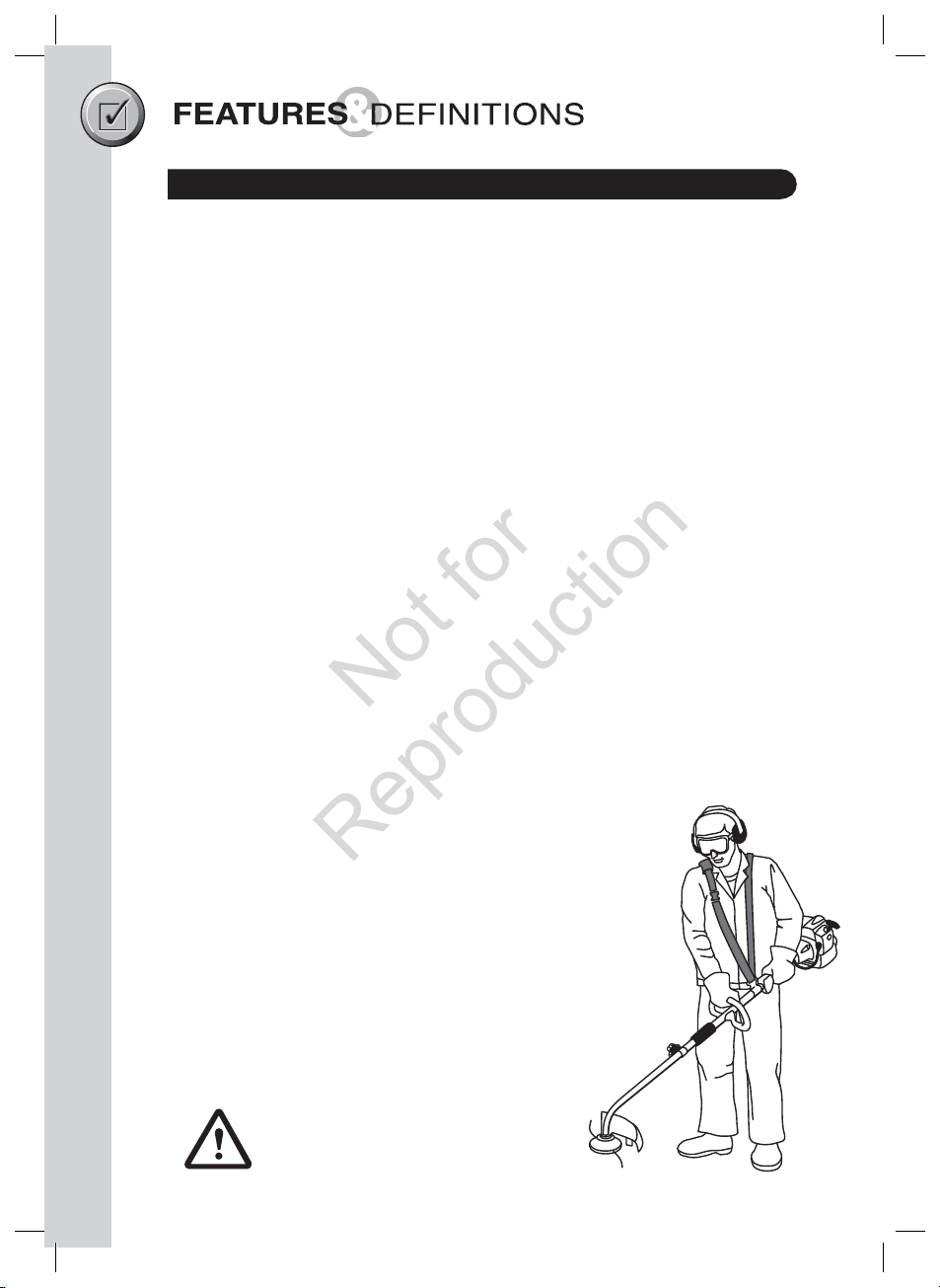
• Wear the necessary safety equipment, as listed on page (12), in Personal Safety
Equipment.
• Always wear heavy, long pants. Do not wear loose clothing, jewellery, short pants,
sandals or go barefoot. Secure hair so it is above shoulder length.
• Do not operate the unit if you are tired, ill or under the influence of alcohol, drugs or
medication.
Unit Safety
• Inspect the entire unit and cutting head before each use.
• Ensure that the guard is properly attached.
• Do not use the unit if it is running erratically. Have it serviced promptly.
• Keep handles free of oil and fuel.
• Learn how to stop the engine quickly in an emergency.
• Stop the engine when the unit is unattended, even for a moment.
• Never allow children or unauthorised persons to operate the unit.
• Do not leave the unit on dry cuttings when it is Hot, as a risk of fire is present.
•Do
• Do not touch the muffler or exhaust - Danger of burns.
not cover muffler or restrict airflow to muffler.
Fuel Safety
• Use a container approved for fuel and a funnel to avoid spillage.
• Mix and pour fuel outdoors where there are no sparks or flames.
• Frequently check for fuel leaks and clean carbon from the muffler at exhaust outlet.
• Do not smoke or allow smoking near fuel, or near the unit, or while using the unit.
• Add fuel before starting the unit.
• Never remove the fuel tank cap while the engine is running or hot, allow to cool
before refuelling.
• Never allow the unit to run out of fuel before refuelling.
• Move at least three metres away from the fuelling site before starting the engine.
• Wipe all traces of fuel on the unit before starting the engine.
• Change your clothes before starting the unit if fuel has been spilt on them.
Not for
Reproduction

Safety Instructions
11
HANDLING
Starting Safety
• Start the engine with feet well away from the cutting head.
• Ensure that the area of starting and operation is clear of sticks, stones, glass, nails,
wire, string and debris, which could be thrown by the cutting head.
Cutting Safety
• Use only in good visibility and favourable weather conditions.
• Keep children, animals and bystanders outside the 15 metre hazard zone. Stop the
engine immediately if approached.
• Keep the engine to the right of your body, holding the unit with both hands.
• Keep a firm footing and balance. Do not over reach.
• Keep the cutting head below waist level and do not raise the engine above your
shoulder. The cutting head can come dangerously close to your body.
• Keep your body away from the cutting head and muffler when the unit is running.
• Do not strike objects that may cause harm or damage to the unit.
Maintenance Safety
• Stop the engine and disconnect the spark plug before clearing blockages, checking
or working on the unit.
• Stop the engine, disconnect the spark plug and inspect the unit if it begins to vibrate
abnormally or if it strikes a foreign object.
• Use only genuine VICTA trimmer line. Never use wire, rope, string, etc.
• Use only genuine VICTA replacement parts.
Transporting and Storage
• Hand carry the unit with the engine stopped, the muffler away from your body.
• Allow the engine to cool, empty the fuel tank and secure the unit before storing or
transporting in a vehicle.
• Empty the fuel tank after each use and before storing the unit.
• Store the unit and fuel well away from sparks or open flames from water heaters,
electric motors, switches or furnaces, etc.
• Store the unit out of reach of children and unauthorised persons.
r
Not for
Reproduction

12
HANDLING
Hazards
Personal Safety Equipment
Always use the following safety equipment when working with your trimmer:
• A safety helmet fitted with a visor or suitable eye protection.
• A set of ear muffs.
• A pair of protective gloves.
• A pair of safety boots.
The following safety precautions must be strictly observed to avoid the risk of damage or
personal injury.
Prior to using the unit, clear the operating area of objects which may
be thrown up by the cutting head, such as rocks, glass and other
debris.
Do not start or operate the unit inside a closed room or building.
Breathing exhaust fumes can kill.
Be careful when operating the unit on slippery ground or overgrown
terrain. Be attentive for concealed hazards, such as ditches, tree
stumps and roots.
Maintain solid footing and balance while operating the unit. Cut only
on ground level.
Never use the unit without the guard securely in place.
Do not touch the cutting head in motion. When handling blades for
assembly or maintenance tasks, always wear protective gloves.
Bystanders must be at least 15 metres away during operation of
the unit (fig 1), as rocks and other materials may be thrown at high
velocities. Switch the unit off immediately if approached.
Keep body away from hot muffler parts.
Not for
Reproduction

Trimmer Flange
Housing
13
ASSEMBLYPROCEDURES
BENT SHAFT (Sabre & Tornado)
1. Replace blade protector.
2. Align hole in flange and housing.
3. Insert Allen Key (supplied) into hole in
flange and housing to prevent rotation.
4. Grip the cast head and rotate
anti-clockwise to remove.
5. Refitting is in reverse order.
Ensure the blade on guard is covered.
Always disconnect spark plug H.T.
lead before any work is done on
the trimmer.
STRAIGHT SHAFT (Tornado Plus and Razor)
1. Replace blade protector.
2.
2.
3.
3.
2. Align hole in flange and housing.
3. Insert Allen Key (supplied) into hole in flange and housing to prevent rotation.
4. Grip the cast head and rotate clockwise to remove.
5. Refitting is in reverse order.
Ensure the blade on guard is covered.
Always disconnect spark
plug H.T. lead before
any work is done on the
trimmer.
NOTE: Not aligning the flange to the housing hole will cause damage.
Trimmer nylon line will deteriorate with time resulting in more frequent
line breakages.
Fitting Trimmer Head
Align housing slot with key hole
Allen Key
Flange
Flange
Housing
Allen Key
r
Line
cutting
blade
Blade
protector
Align housing slot with key hole
Not for
Reproduction

(1) Cut a length of line to 44cm, or use Victa part number TR00200A. Bend it in half
(equal ends). Use only 3mm diameter Nylon line (Fig: 1)
(2) Push the bent end of the line under the lug of the trimmer head
(3) Push one end of the line into the hole on the same side of the head as the line end.
Pull the line through the hole until loops or slack between the hole and centre lug is
removed.
(4) Repeat step 3 for opposite side. (5) Refer to image for correct complete assembly of
the nylon line into the head.
(6) To remove used line, bend new line as in (1), slide new line under used line through
slot in cast head.
(7) Holding both ends of the new line together, pull the old line out of the cast head.
Repeat process for the other side (8).
Fitting Trimmer Line
Removing Trimmer Line
4
3
7 8
21
Bend middle
5 6
Slot in
cast
head
14
ASSEMBLYPROCEDURES
Not for
Reproduction

15
ASSEMBLYPROCEDURES
Only use genuine VICTA 3mm diameter nylon trimmer line.
Always trim with the correct length of nylon line.
Always ensure that all components are firmly fastened before
starting any operation.
Unequal lengths will cause vibration and damage to unit.
Excessive trimmer line length will damage guard and clutch.
Replace line when 50mm from trimmer head body
Remove used line by pushing back into trimmer head or by levering
out.
Fitting Trimmer Line
Not for
Reproduction

16
ASSEMBLYPROCEDURES
Shaft Assembly
Assembling
Connection Types - Victa Trimmers have two types of split shaft connections;
the split shaft
(Sabre, Tornado,
1. Standard Connection (Fig 5) - Drive shafts may require alignment before sliding together.
2. “EASY LINK” Connection (Fig 6) - Drive shafts will automatically align when sliding together.
The two illustrations below will help identify which type of connection you have purchased.
Please refer to this information when fitting alternative Victa Attachments.
Tornado Plus only)
1. Slacken the star grip screw (1) on the split shaft
connection. (see Fig 1)
2. Then press lever on the shaft split connection (2)
and carefully slide the lower shaft (4) into the
shaft split connection (3). (see Fig 1 & 2)
When doing so, take care to ensure
the
drive shafts on the insides of the
tubes
slide into each other.
(turn the trimmer head gently if required)
3. Ensure that the lever on the shaft split connection
locks into the corresponding hole (5). (see Fig 3)
4. Then re tighten the star grip screw (1). (see Fig 4)
5. To dismantle, proceed in reverse order.
Take care when
when fitting
& tightening.
Beware of
pinch points
DO NOT MIX DRIVE SHAFT CONNECTION TYPES
Standard Connection
Fig. 1
Fig. 3 Fig. 4
Fig. 2
STANDARD CONNECTION
SHOWN
Easy Link Connection
Fig. 5 Fig. 6
Not for
Reproduction

17
ASSEMBLYPROCEDURES
Fitting the handle
1 Slacken the wing nut on the fastening screw on the handle.
2 Remove the wing nut, washer and fastening screw from the handle.
3 Push the Classic handle onto the shaft.
4 Replace fastening screw and tighten with the wing nut.
Not too loose or too tight. Over tightening may damage the unit.
Universal Handle
Classic Handle
Correct Wrong
2
1
3
Fitting the handle
(1) Components - 2 nuts, 'D' Grip Handle, Toggle
handle and 'U' Bolt.
(2) Place Universal Handle (2) over shaft.
(3) Insert Toggle Handle (3) around shaft and into
holes in Universal Handle.
(4) Screw on nuts (1) onto threads of 'U' Bolt by
fingers only, with toggle in open position.
(5) Be sure only to thread nuts (1) down so the
Toggle Handle has enough grip onto the shaft,
when levered into the close position.
Not too loose or too tight. Over tightening may damage the unit.
Toggle open position Toggle closed position
Not for
Reproduction

18
ASSEMBLYPROCEDURES
Fitting the bent shaft guard
• Slacken the fastening screw on the guard with the help of the Allen key provided and
then remove.
• Then clip the guard to the lower bent shaft.
• Screw the guard hood tightly in position with the fastening screw.
Make sure the guard is located on the housing before securing in
position.
Fitting the straight shaft guard
1. Remove two screws from guard (Fig 1).
2. Position guard under the securing saddle (Fig 2).
3, Secure the two screws into the guard (Fig 3).
Fitting the carrying strap
• The strap is intended to help you work safely and ergonomically with the petrol grass
trimmer.
• Hook the strap into the fastening eyelet.
• Slip the strap over the shoulder.
• Set the length of the shoulder strap in such a way that the trimmer head runs parallel
to the ground. In order to establish the optimum length of the strap, you should then
make a few swinging movements without starting the engine.
Before Assembly
Fig: 1 Fig: 2 Fig: 3
Not for
Reproduction

19
OPERATINGINSTRUCTIONS
Check the position & operation of controls to ensure you are
comfortable before you start using the machine. Triggers, starter cord
and grip position should provide smooth operation, balance & comfort
before starting the machine. Check that all screws are securely fastened
and also check all the safety devices.
Always use the shoulder strap when using the appliance.
Switch off the engine before you take off the shoulder strap.
Check the machine for the following each time before use:
sThat there are no leaks in the fuel system
sThat the cutting unit and all safety devices are in perfect condition
sThat all screws are securely fastened
Fuel and oil
Recommended fuels
sUse only a mixture of normal unleaded petrol and 2-stroke engine oil. Mix the fuel
sVicta Trimmers require a mixture of petrol and oil in the fuel tank.
mixture as indicated on the fuel mixing table.
sStart the machine at least 3 m away from the refuelling site to avoid the possible risk
of fire.
sDo not smoke whilst refuelling or working with the machine.
sDo not use the trimmer near inflammable liquids or gases. This could result in an
explosion and/or fire.
Do not use a fuel mixture which has been kept for longer than 90
days, it may damage the unit.
Use Non-Victa makes of 2-stroke oil at the mixing ration of 25:1
If inadequate lubrication causes engine damage, the
manufacturer's engine warranty will be void.
Only use containers designed and approved for the purpose to
transport and store fuel.
sPour the correct quantities of petrol and 2-stroke oil into a container. Then shake the
container well, before filling the trimmer fuel tank.
Fuel mixture table
lioekorts-2)dedaelnu(lorteP
l (Non Victa Formula V 2-Stroke Oil)
m002ertil5
Mixing procedure: 25 parts petrol to 1 part oil
lm001ertil5 (Only for Victa Formula V 2-Stroke Oil)
Mixing procedure: 50 parts petrol to 1 part oil
Before Starting Machine
USE Clean fresh “Regular Unleaded Fuel”
Fuel with up to 10% ethanol can be used - 25:1 Fuel/Oil Ratio
Not for
Reproduction

20
OPERATINGINSTRUCTIONS
A blade on the underside of the guard
hood automatically cuts the cutting
line to the optimum length. This is
covered by a guard. Remove the guard
before you start working and replace it
when you have finished working.
Starting the engine when cold
Fill the tank with the required amount of oil/petrol mix. See Fuel and oil.
(1) Set the machine down on a hard, level surface.
(2) Set the choke lever to the ‘COLD’ position.
(3) Press the fuel pump (primer) 10 times (this is found under the air filter housing).
(4) Ensure the 'STOP SWITCH' (4) is set to the 'ON' position.
(5) To secure throttle lever:
a. Press throttle release (1)
b. Press throttle lever (2)
c. Press throttle lock (3)
d. Let go of the throttle release (1)
& throttle lever (2).
Note: By repressing the throttle lever this will
release the throttle lever from the locked position.
(6) Hold the machine firmly and pull out the starter cord until you feel it start to resist.
Then tug sharply on the starter cord 4 times. The machine should start.
Never allow the starter cord to snap back. This may damage the machine.
(7) Once the engine has started, move the choke lever immediately to the ‘HOT’ position
and allow the machine to warm up for approx. 10 seconds.
•If the engine does not start up, repeat steps 6-7 above.
Operation
PRIMER
Line cutting
blade
Blade
protector
1.
2.
4.
3.
Choke
Not for
Reproduction
This manual suits for next models
3
Table of contents
Other Victa Trimmer manuals
Popular Trimmer manuals by other brands

Tanaka
Tanaka TCH 22EAP2 Handling instructions

Grizzly Tools
Grizzly Tools BHS 2670 E2 Translation of the original instructions for use

Craftsman
Craftsman WEEDWACKER 358.795150 instruction manual

Shindaiwa
Shindaiwa 22T Owner's/operator's manual

Stiga
Stiga HT 500 Li 48 Operator's manual

Hyundai power products
Hyundai power products HDBT24-1 instructions