INDEX
Hazard Identification . . . . . . . . . . . . . . . . . . . . 4
Operator Safety Instructions. . . . . . . . . . . . . . . 4
Introduction...........................6
Receiving the Tool......................6
VE460 Large Container Contents . . . . . . . . . 6
VE460 Small Container Contents . . . . . . . . .6
Tool Nomenclature......................7
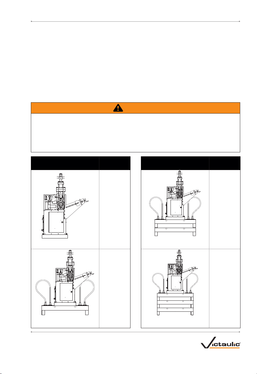
Tool Setup for Grooving 24-inch/610.0-mm
and Smaller Pipe Sizes . . . . . . . . . . . . . . . . 8
Important Information for Tool Setup . . . . . . . 10
Tool Setup for Grooving 26-inch/660.0-mm
and Larger Pipe Sizes . . . . . . . . . . . . . . . . 11
Power Requirements . . . . . . . . . . . . . . . . . . . 17
Power Hookup and Verification of Pipe
Rotation Direction . . . . . . . . . . . . . . . . . . . 17
Preparing Pipe for Grooving . . . . . . . . . . . . . .20
Pipe Length Requirements. . . . . . . . . . . . . . . 21
Checking and Adjusting the Tool Prior to
Grooving ..........................23
Grooving Rolls ......................23
Adjusting the Roll Guards. . . . . . . . . . . . . . 23
Pipe Stabilizer Adjustment . . . . . . . . . . . . . 26
Ram Speed Adjustment . . . . . . . . . . . . . . .28
Dwell Control Adjustment. . . . . . . . . . . . . . 29
Time Range Adjustment. . . . . . . . . . . . . . .29
Pipe Size Adjustment. . . . . . . . . . . . . . . . . 30
Groove Diameter Stop Adjustments . . . . . . 30
Grooving Short Pipe Lengths . . . . . . . . . . . . .33
Grooving Long Pipe Lengths . . . . . . . . . . . . .35
Roll Changing ........................39
Lower Roll Removal . . . . . . . . . . . . . . . . . . 41
Upper Roll Removal. . . . . . . . . . . . . . . . . . 41
Upper Roll Installation . . . . . . . . . . . . . . . . 42
Lower Roll Installation . . . . . . . . . . . . . . . .43
Maintenance .........................46
Lubrication ........................46
Checking and Filling Gear Reducer Oil. . . . 47
Checking and Filling Hydraulic Oil . . . . . . . 47
Replacing Hydraulic Oil and Filter . . . . . . .48
Air Bleeding........................51
Recommended Lubricants. . . . . . . . . . . . . . . 53
Bearing and Slide Grease. . . . . . . . . . . . . .53
Gear Oil...........................53
Hydraulic Oil .......................53
Parts Ordering Information. . . . . . . . . . . . . . . 53
Troubleshooting.......................54
Tool Rating and Roll Selection . . . . . . . . . . . .56
Original Groove System and “ES” Rolls for
Steel and Schedule 40 Stainless Steel Pipe -
Color Coded Black. . . . . . . . . . . . . . . . . . . 56
Original Groove System Rolls for Aluminum
and PVC Plastic Pipe - Color Coded Yellow
Zinc..............................58
Original Groove System Rolls for Schedule 5S
and 10S Stainless Steel Pipe - Color Coded
Silver.............................59
RW Rolls for Grooving Standard-Weight Steel
Pipe to AGS Specifications - Color Coded
Black with Yellow Band . . . . . . . . . . . . . . . 60
RWX Rolls for Grooving Schedule 5S and 10S
Stainless Steel Pipe to AGS Specifications -
Color Coded Silver with Black Band. . . . . .60
Explanation of Critical Roll Groove
Dimensions ........................62
Roll Groove Specifications -
Original Groove System for Steel and
Stainless Steel Pipe . . . . . . . . . . . . . . . . . .63
Roll Groove Specifications -
Original Groove System for Steel Pipe and
All Materials Grooved with “ES” Rolls. . . . .65
Roll Groove Specifications - Advanced Groove
System (AGS) Roll Groove . . . . . . . . . . . . . 66
Advanced Groove System (AGS) Roll Grooving
Specifications for Carbon Steel Pipe . . . . .67
Advanced Groove System (AGS) Roll Grooving
Specifications for Stainless Steel Pipe . . . . 69
TM-VE460_3
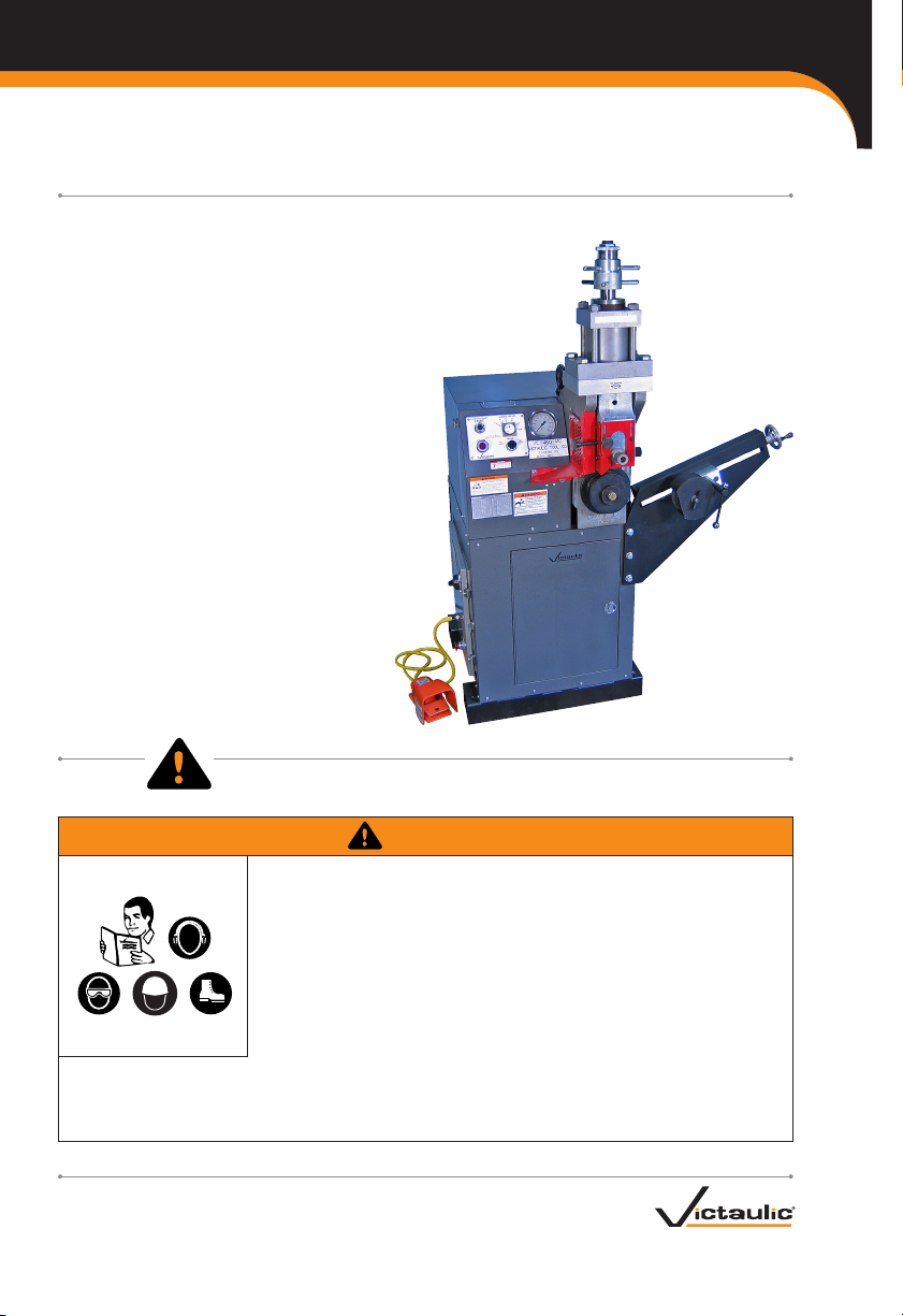
TM-VE460OPERATING AND MAINTENANCE INSTRUCTIONS MANUAL
www.victaulic.com
VICTAULIC IS A REGISTERED TRADEMARK OF VICTAULIC COMPANY.
REV_A