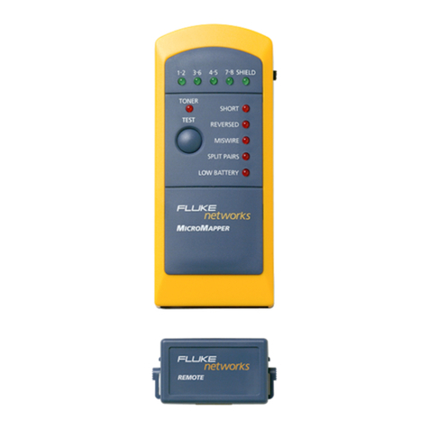
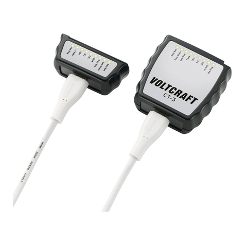
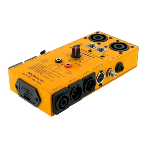
Victor 668 User manual

Инструкция по
эксплуатации
кабель-тестера
VICTOR 668

Cable tracker
Operation Manual
Thank you for using our product.
In order to learn about the correct operating method,
functions and inspection and maintenance essentials of
the product and make the product rugged and durable,
please read the manual carefully before using the
product.
Warning: Incorrect contact with electrical appliances
may result in serious injuries or even death because of
electric shocks. Thus, you are expected to operate in
strict line with the manual to avoid such accidents.
. Please read the whole manual carefully and operate
the product in strict line with it, otherwise the
protection function designed by the factory will fail
or be impaired.
2. If the product has any damage such as cracking of
its shell or falling of its battery cover or the shell,
1

do not use it.
3. Do not use the product in electric storms, wet
weather or thunderstorm weather.
4. Do not detect high-voltage cable lines (such as
220V power supply lines) with the product.
5. Do not use the product in a place with any
combustible gas or much dust or vapor.
6. Keep in mind that safety is the most important
thing: Voltages larger than 30VAC or 60VDC
highly tend to result in electric shocks.
7. Use appropriate personal protection equipment such
as safety goggles, mask, insulating gloves,
insulating shoes and insulating rubber mat.
8. In hot-line work, do not ground by yourself;
connect the ground wire and the null line first when
using a crocodile clip test line or an adapter jumper.
I. Product overview
The handheld multifunctional cable tracker is widely
used in networks, telecommunication, broadcasting and
TV, security protection, electric power, etc. It applies to
detect cable such as network cables, telephone cables
2
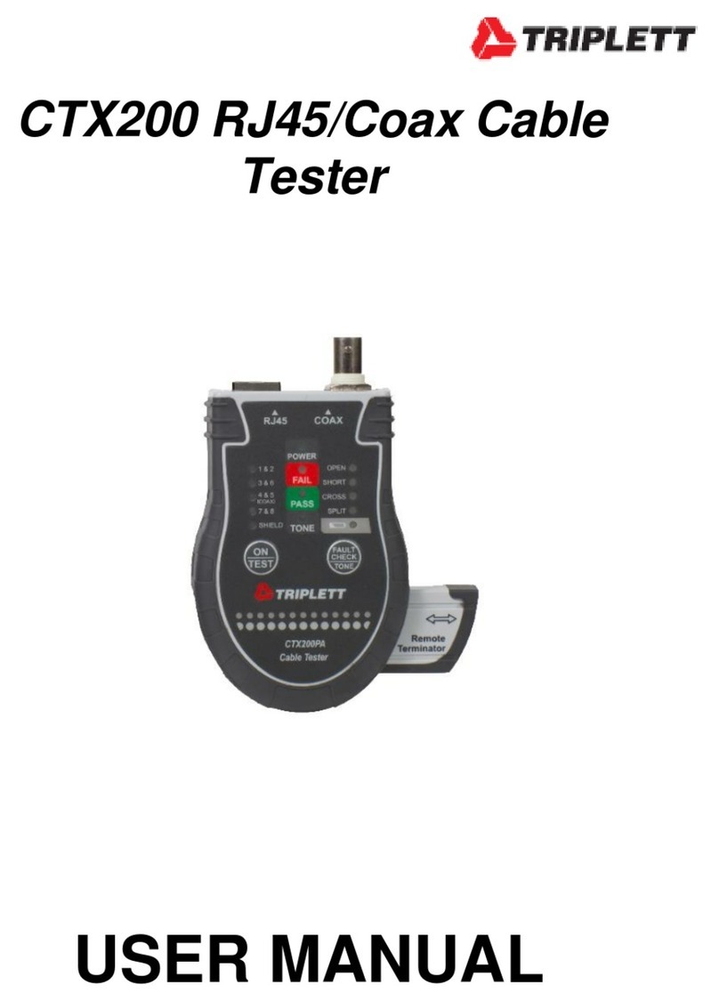
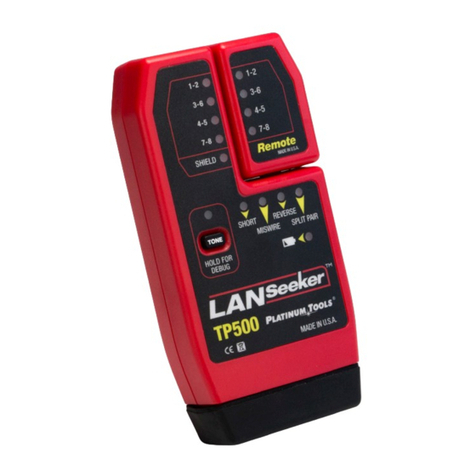
and metallic cables and connectors such as RJ
connectors and R45 connectors. It is a necessary
detection device for the persons taking work in fields
including networks, telecommunication, broadcasting
and TV, security protection, electric power, etc.
3

Safety instruction
Warning
4

Please read the manual carefully to avoid electric
shocks, burns and other injuries.
II. Technical indexes and specification
Transmission signal distance: <200m
Low voltage indication: Automatic low battery
detection; on status of the low voltage indicator when
the battery voltage is lower than the operating voltage
Sampling frequency: 2.5 s/time
Power source: 9V batteries, 006P
Dimensions: 40 mm × 66 mm × 28 mm; 265 mm × 50
mm × 33 mm
Product weight: approximate 280 g
Total weight: approximate 460 g
Standard accessories: a quality certificate, an operation
manual, two 9V batteries, a RJ45 cable, a RJ cable, a
pair of crocodile clip for RJ connector, a headset and
a bag for portability
Operating temperature: 0 ~ 4 (≤80%RH)℃
Storage temperature: - 0 ~ 5 (≤95%RH)℃
III. Functions
5

□ Network cable matching (RJ45)
□ Telephone cable tracking (RJ )
□ Network cable tracking (RJ45)
□ Power cable tracking (RJ )
□ Value and polarity of DC level
□ Connectivity status and impedance of cable
□ Switching between two frequencies during cable
tracking
IV. Features of functions
Cable tracking
The product can find out target cables among many
cables including telephone cables, network cables and
other metallic cables quickly and accurately via RJ
jacks and RJ45 jacks directly. The product is
particularly designed with the function of cable tracking
when Ethernet switches, routers and PC terminals are in
an on status.
Cable matching
It can check the sequence, short or open circuit,
correctness, reverse connection and crossing of each
network cable. This function is visualized and
6

convenient and can replace a network tester.
The product can be easily used in dim places because of
an LED lamp.
The product is provided with a headset for the sake of
easy use in noisy places.
The product can prompt an undervoltage status of the
batteries.
V. Operation instructions for functions
. Cable tracking
The product can track telephone cables, network cables
and other metallic cables via RJ jacks and RJ45 jacks
directly. It can realize cable tracking when Ethernet
switches, routers and PC terminals are in an on status.
However, it should never be used for detecting live
cables, particularly high-voltage cables.
Operating method
) Press the power switch button of the transmitter,
select the cable tracking function through the
function selection button (the cable tracking LED
indicator will be lit) and connect the target network
7

cable or telephone cable to the corresponding jack
(such as RJ or RJ45) of the transmitter or connect
a target metallic cable to the RJ jack via the
standard accessory crocodile for RJ connector.
2) Hold the receiver and press the cable tracking start
button. When the target cable is being detected, the
indicator (red) at top of the receiver will detect at
the other end of the target cable (such as in the
space close to the cables of a telephone distribution
cabinet, a junction box, a concentrator or a switch)
and compare sounds of the receiver. The cable with
the loudest sound when the probe is reaching it will
be the cable to be tracked.
During detection, the transmission signal frequency
switching button can be pressed to switch to another
transmission signal frequency.
During detection, the volume can be adjusted through
the volume adjustment knob on the receiver. In a noisy
place, the headset can be inserted into the headset jack
to be used.
2. Cable matching
8

The product can check the sequence, short or open
circuit, correctness, reverse connection and crossing of
each network cable. It can realize cable tracking when
Ethernet switches, routers and PC terminals are in an on
status. However, it should never be used for detecting
live cables, particularly high-voltage cables.
Operating method
) Press the power switch button of the transmitter,
select the cable matching function through the function
selection button (the cable matching LED indicator will
be lit) and connect the target network cable to the RJ45
jack of the transmitter and the RJ45 jack of the receiver.
The transmitter will track cables from to 8 and G and
the receiver will track cables following the same
sequence.
3. Telephone or DC level and polarity
) Judge whether a telephone cable is normal or not;
a) Press the power switch button of the transmitter and
select the telephone function through the function
selection button (the telephone function LED indicator
will be lit);
9

b) Insert a local call telephone cable connector into the
RJ jack of the transmitter. If the ‘Telephone’ function
LED indicator is lit, it suggests that the telephone cable
is normal, otherwise it suggests that the telephone cable
has a fault.
2) Judge the unoccupied, ringing or off-hook status of
an operating telephone cable;
a) Press the power switch button of the transmitter and
select the telephone function through the function
selection button (the telephone function LED indicator
will be lit);
b) Insert a local call telephone cable connector into the
RJ jack of the transmitter. If the ‘Telephone’ function
LED indicator is lit, it suggests that the telephone cable
is unoccupied; if the ‘Telephone’ function LED
indicator has dimmed, it suggests that the telephone
cable is in an off-hook status; if the ‘Telephone’
function LED indicator is flickering, it suggests that the
telephone cable is ringing.
3) Detect value and polarity of the DC level (only the
transmitter is needed).
10

a) Press the power switch button of the transmitter and
select the telephone function through the function
selection button (the telephone function LED indicator
will be lit);
b) Insert the RJ plug of the crocodile clip for RJ
plug into the RJ jack of the transmitter and clamp the
detected telephone cable with the red clip and the black
clip.
c) If the ‘Telephone’ function LED indicator is lit, it
suggests that the red clip is the positive electrode and
the black clip is the negative electrode, otherwise it
suggests that the red clip is the negative electrode and
the black clip is the positive electrode, or that the cable
is not live (in this case, change the polarity and detect
again);
d) Level value judgment: The lighter the LED, the
higher the level value will be; the dimmer the LED, the
lower the level value will be. The detectable range is
9VDC to 00VDC.
4. Connectivity and impedance of cable
a) Detect with the transmitter only. Press the power
11

switch button of the transmitter and select the on-off
function through the function selection button (the on-
off function LED indicator will be lit). The transmitter
will then begin to operate. Insert the RJ plug of the
crocodile clip for RJ plug into the RJ jack of the
transmitter and clamp the detected cable with the red
clip and the black clip. If the on-off function LED
indicator is lit, it suggests that the cable is on. The
smaller the cable impedance, the brighter the on-off
function LED indicator will be.
b) Detect with the cable tracking method. The operating
method is the same as that in the cable tracking
function. If a voice frequency can be detected at the
other end of the cable by the receiver, it suggests that
the cable is on.
5. Undervoltage status prompt
Both the transmitter and the receiver can indicate an
undervoltage status of the batteries.
In the case of an undervoltage status (lower than 6V) of
the batteries, the four LED indicators on the transmitter
will flicker.
12

In the case of an undervoltage status (lower than 6V) of
the batteries, the low voltage LED indicator on the
receiver will be in yellow.
VI. Product maintenance
Clean the product surface at regular intervals with wet
cloth and a little detergent rather than grinder or
chemical solvent. Do not put the product in a place with
any chemical component or dismantle it without
permission because it may result in damage. Check the
batteries at regular intervals.
VII. Troubleshooting
If the product fails to operate normally, inspect and
maintain it with the following methods which can
eliminate ordinary faults. If the faults cannot be
eliminated with these methods, contact our maintenance
center or dealers.
Fault Location and method of inspection Detection
failure
. Connect the power source; or
2.Replace the batteries.Off status of indicator
. Replace the batteries.Failure of the speaker
13

. Replace the batteries.
The manual is subject to change without notice.
Content of the manual is believed correct. If you find
any mistake or missing content, please contact us.
We will not assume responsibility for the accidents and
harms due to improper operation by users.
Users should not regard the functions described in the
manual as their causes for using the product for other
purposes.
14