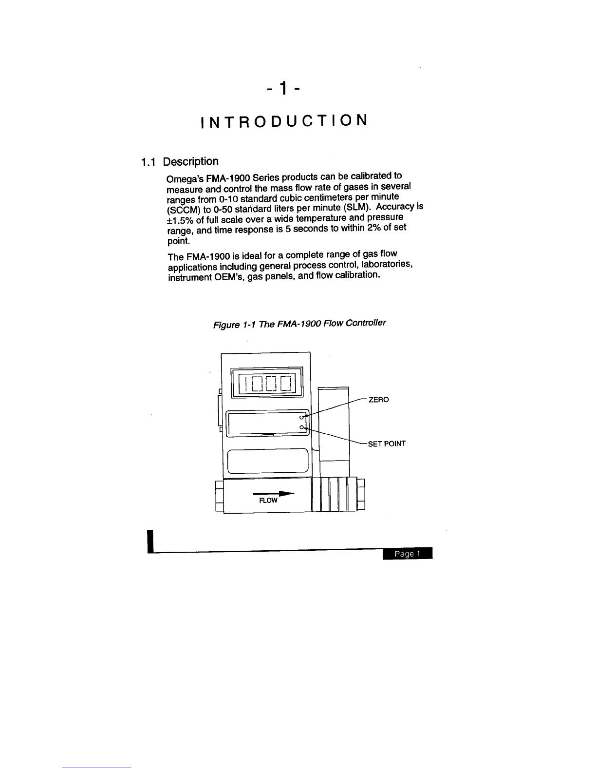
Omega MASS FLOW FMA-1900 User manual

EMC/EMI
regulations that
apply. OMEGA is constantly pursuing certification of its products to the European New Approach
Directives. OMEGA
will add
the CE mark to every appropriate device upon certification.
The information contained in this document is believed to be correct but OMEGA Engineering, Inc. accepts
no liability for any errors it contains, and reserves the right to alter specifications without notice.
WARNING: These products are not designed for use in, and should not be used for, patient connected applications.
It is the policy of OMEGA to comply with all worldwide safety and
(1455)
283912 FAX: 44 (161) 777-6622
Toll Free
in England: 0800-488-488
e-mail:
(161)
777-6611
FAX: 44
5EX,
England
Tel: 44 (1455) 285520 Tel: 44
M44
6TU,
England
7
Omega Drive,
Broughton Astley, Leicestershire, Irlam, Manchester,
LE9
P.O.
Box
25 Swannington Road,
(07056)
8540
Toll Free in Germany: 0130 112166
e-mail:
(07056)
3017 FAX: 49
FAX: 33 0130-699-120
Daimlerstrasse 26, D-75392 Deckenpfronn, Germany
Tel: 49
05-4-06342
e-mail:
Papin,
78190 Trappes
Tel: 33 0130-621-400
Toll
Free in France;
Denis
(69)
6311899
9, rue
Ostravska 767,733 01 Karvina
Tel: 42
(31)
20 6434643
Toll Free in Benelux: 06 0993344
e-mail:
(31)
20 6418405 FAX:
8034,118O
LA Amstelveen, The Netherlands
Tel:
Postbus
Servicing Europe:
(203)
359-1660 ext: 2203 e- m ail:
Espaiiol:
800-TC-OMEGAsM
FAX: (95) 203-359-7807
En
(95)
l-SOO-USA-WHENSM
TELEX: 996404 EASYLINK: 62968934 CABLE: OMEGA
Tel:
/
l-800-622-BE!?P
Engineering Service: l-800-872-9436
/
l-SOO-TC-OMEGASM
Customer Service: l-800-622-2378
/
Is0
9002 certified
Sales Service: l-800-826-6342
359-7700
FAX: (514) 856-6886
For i mmed iate technical or application assistance:
USA
and Canada:
Mexico and
Latin America:
Benelux:
Czech Republic:
France:
Germany/Austria:
United Kingdom:
(203)
FAX :
5Al
Tel: (514) 856-6928
e-mail:
H7L
Bergar
Lava1 (Quebec)
(203)
359-1660
976
06907-0047
Tel:
Crrtifiod
Canada:
One
Omega Drive,
Box 4047
Stamford, CT
IS0
9001
USA:
OMEGAneP
On-Line Service
Internet e-mail
Servicing North America:

M248310898
to
searchforleaks
inside oroutsidetheFMA-1900. Instead,monitorpressure decay.
Operator’sManual
B
Do notuseliquidleak detectors
510%.
Ifyou are providingyourown
powersource, refer to Section 2.3,paragraph 8, forspecific power
supplyrequirements andjumpersettings.
@
24VDC
mV
RMSripple)withthe abilityto provide atleast6
watts(250mA)
B
The FMA-1900controller requires a 24VDCregulated
powersupply(50
mA
outputorinputsection.
B
The FMA-1900is notaloop powered device!Do NOT
apply power tothe 4-20
(5O”C),
respectively.
122°F
kg/cm*
gauge)or
B
Themaximumpressure andtemperatureintheflowlinein
which yourFMA-1900isto beinstalledshould notexceed 150 psig
(10
m
Over-tighteningthe pipeconnectionmay crackthe
fittings orshift thecalibration of theFMA-1900controller.
B
OmegaEngineeringis notliableforany damages or
personal injury,whatsoever, resultingfromthe use ofOmega’smass
flowmeters orcontrollerswith oxygen gas.Althoughthemassflow
meters and controllers are cleaned prior to shipment,wemake no
claimorwarrantythat theircleanlinessrendersthemsafeforoxygen
service.ThecustomermustcleanOmega’smassflowmeters or
controllerstothe degreethat theyrequirefor theiroxygenflow
applications.This statementdoes not replace productwarranty.

SetpointConfiguration
...................................................
15
3.10
Cold Sensor Lockout Circuit
..........................................
16
3.11 Auto Shut-Off
.................................................................
16
SetpointInput Signal
......................................................
13
3.9
Setpoint
Adjustments
............................
12
3.6
Mounting
Position..........................................................
13
3.7
Output Options
...............................................................
13
3.8
mA
Output Signal
...........................................
12
3.5
Zero and
Local
..................................
11
3.3
Overranging
...................................................................
12
3.4
The 4-20
_.
11
3.2
Accuracy
.....................................
.......................................................
...................................................................................
11
3.1
Referencing the Flow Rate to Other Temperature and
......
Pressure
Conditions
.
1.1
Description.. .....................................................................
1
1.2
Specifications
..................................................................
2
2. Installation
..................................................................................
4
2.1
Receipt of Your
FMA-1900
...............................................
4
2.2
Return
Shipment..............................................................
4
2.3
Before Beginning the Installation
.....................................
5
2.4
Mechanical Installation
....................................................
7
2.5
Plumbing
Connections
.....................................................
8
2.6
Electrical
Connections
.....................................................
9
3.
Operation
FMA-1900 SERIES FLOW CONTROLLERS
TABLE O F
CONTENT S
1
Introduction
............................................................................
1

.,............................. 19
Appendix C K-factors and Gas Tables
. . . . . . . . . . . . . . . . . . . . . . . . . . . . . . ..*..........
20
FMA-1900 SERIES FLOW CONTROLLERS
TABLE O F
CONTENTS CONTINUE D
3. Operation (continued)
3.12 On/Off Control
...............................................................
16
3.13Purging of Mass-Trak Products
.....................................
17
3.13.1 Purging of Non-reactive
Gases
.....................................
17
Appendix A Pin Connections
..........................................................
18
Appendix B Purge and Valve Off Connections

I-
1 The FMA- 1900 Flow Controller
ZERO
SET POINT
+1.5%
of full scale over a wide temperature and pressure
range, and time response is 5 seconds to within 2% of set
point.
The FMA-1900 is ideal for a complete range of gas flow
applications including general process control, laboratories,
instrument OEM’s, gas panels, and flow calibration.
Figure
-I-
INTRODUCTIO N
1.1
Description
Omega’s FMA-1900 Series products can be calibrated to
measure and control the mass flow rate of gases in several
ranges from O-l 0 standard cubic centimeters per minute
(SCCM) to
O-50
standard liters per minute (SLM). Accuracy is

flO%
SLM/24
VDC
flO%;
0 to 50SLM/15VDC
mA
into 1000 ohm
maximum load resistance for 24 VDC supply (500 ohm/l5
VDC supply).
CONTROL RANGE: Calibrated for 10 to 100% of full scale.
INPUT POWER: 0 to 15
kg/cm*)
optimum.
GASES: Most gases (e.g., air, nitrogen, methane, carbon
dioxide, argon, helium, hydrogen); check compatibility with
wetted materials; specify when ordering.
OUTPUT SIGNALS: Linear O-5 VDC into 2000 Ohm minimum
load resistance standard or linear 4-20
kg/cm*)
differential standard; 30 PSI (2(0.35-3.5
nm3/h).
FMA-1900 SERIES MINIMUM DP REQUIREMENTS: 5-50
PSI
“C(70°F). Other ranges in other units are available (e.g.,
SCFH or
.l
“D”
connector is provided for power input, output signal and set
point control. FMA-1900 is available in several basic configu-
rations with either NPT (female) or compression inlet/outlet
fittings, and with or without the optional power supply.
l&Specifications
FLOW RATES: O-10 SCCM to O-50 SLM; flow ranges speci-
fied are for an equivalent flow of nitrogen at 760 mm Hg and
21
15-pin
mA
output
signals, which are linearly proportional to gas mass flow rate,
are provided for recording, data-logging, or control. A
The versatile FMA-1900 product digitally displays the mass
flow rate directly in engineering units or percent of full scale.
The FMA-1900 is a transducer requiring a regulated 24 VDC
external power source. The O-5 VDC and 4-20

mA
into 250
Ohms input impedance.
mA
and 4-20
SETPOINT
COMMAND SIGNALS: O-5 VDC (O-10 VDC
optional) into 22000 Ohms. O-20
“C”-rings.
66;316 stainless steel,
430F stainless steel; nickel plating; Viton
Nyton
WEllED
MATERIALS:
10% glass-filled
GASANDAMBIENTTEMPERATURE:
32” to 122°F (0 to 50°C)
valve.)
cc/set
of helium maximum
to outside environment.
(Not recommended for use as a positive
shutoff
lo-‘ATM
kg/cm*)
gauge optimum.
LEAK INTEGRITY: 1 x
kg/cm*)
gauge maximum;
20 PSI (1.4
kg/cm*),
or better:
RESPONSE TIME: One second to 63% of final value.
GAS PRESSURE: 150 PSI (10
“C,
or better.
PRESSURE COEFFICIENT: 0.02% of full scale per PSI (0.07
COEFFICIENTI
0.08% of full scale per
scale.
TEMPERATURE
of
full
&0.25%
REPEATABILIW
O-100%
of full scale.
fl.5%
of full scale from 1ACCURACY

2.2
Return Shipment
Do not return any equipment without a Return Authorization,
obtainable from the Customer Service Department at the
number shown above.
Information describing the problem, the corrective action or work to
be accomplished at the factory, the purchase order number under
which the work is to be done, and the name of person to contact
must be included with the returned equipment.
NOTE:Equipment returned for repair that is found to be com-
pletely operational will be subject to the current “no problem
found” billing rate.
In a case such as this, Omega will attempt to
identify possible problems with the installation or application.
(800~USA-WHEN).
Have your purchase order and model number available.
2.1
Receipt of Your FMA-1900
After receiving your FMA-1900, carefully check the outside of
the packing carton for damage incurred in shipment. If the
packing carton is damaged, notify the carrier at once regarding
their liability. A report with the serial number and part number
should be submitted to Customer Service. Call 800-622-2378
for detailed instructions.
Remove the packing slip from its envelope and check that the
carton contains all parts listed. Make sure spare parts or
accessories are not discarded with the packing material. In
case of shortages, contact 800-872-9436
-2-
INSTALLATIO N

mA
is for zero flow.
mA
is for one-half of full scale; and 4.00
mA
is the output signal for the full scale; 12.00
mA
output
signal, 20.00
linearty
proportional to the gas
mass flow rate. The full scale range and the gas for which
the unit was calibrated are shown on the FMA-1900 data
tag. Section
2.6,
ELECTRICAL CONNECTIONS, describes
the electrical output signal hookup. For example, if you are
monitoring the O-5 VDC output signal, 5.00 VDC is the
output signal for the full scale listed on the FMA-1900 data
tag; 2.50 VDC is for one-half of full scale; and 0.00 VDC is
for zero flow.
If you are monitoring the 4-20
mA
output signals. The effective
control range of the unit is 10% to 100% of the calibrated
flow range. The output is
mA
output or input section.
4.
After the warm-up period, your FMA-1900 will begin
monitoring the gas mass flow rate.
5.
Output Signals: The FMA-1900 has either O-5 VDC (O-l 0
VDC optional) or 4-20
4mA,
depending on output configu-
ration). Allow at least 15 minutes for complete warmup.
CAUTION:
The FMA-1900 is not a loop powered device!
Do NOT apply power to the 4-20
“D”
connec-
tor on the side of your FMA-1900, then plug the power
supply into line power. If you are providing your own
power source, refer to Section 2.3, paragraph 8, for
specific power supply requirements and jumper settings.
3.Upon application of power, the output signal will be at a high
level for the first 10 to 20 seconds, after which (assuming zero
flow) it will drop to 0 VDC (or
15-pin
kg/cm*
gauge) or 150°F (66°C). Maximum
operating pressure differential is 50 psig.
2.
Apply power to your FMA-1900. If you are using the
Omega power supply, connect it to the
l/4-inchpipe, use a good
quality paste pipe thread sealant. First tighten the fittings
by hand, then tighten no more than one and a half turns to
avoid cracked fittings or creating a calibration shift.
The line pressure and temperature should not exceed 150
psig (10
2.3
Before Beginning the Installation
Read the following notes in their entirety before beginning
actual installation of your FMA-1900 flow controller.
1.
Using the flow direction arrow on the FMA-1900 to prop-
erly orient the controller, install the FMA-1900 into the gas
flow line. If you are utilizing

[
15 to 250 SLM].
A regulated power supply is required. Ripple content
should not exceed 50mV peak to peak.
Refer to the component location diagram (Figure 3-2) for
the location of Jumper J3.
250mA,
Jumper J3 open (shorting block
removed)
@
160mA,
Jumper J3 closed (shorting block
installed) [If less than 15 SLM].
24 VDC
@
%).
Overrange conditions are indicated by the display and/or
output going to a high level, above the full scale range.
After the over-range condition has been removed, it may
take several minutes for the FMA-1900 to recover and
resume normal operation.
The FMA-1900 has more stringent power supply require-
ments due to the presence of the valve.
Because the valve
is operated in a control loop, power supply variations
cannot be tolerated. This means the power supply must be
a regulated 24 VDC with ripple not to exceed 50mV peak to
peak, and capable of producing at least 250mA (6 watts).
The standard power supply for both the FMA-1900 is 24
VDC. It is possible to operate the FMA-1900 on 15 VDC at
reduced performance levels. There is a direct relationship
between the amount of power the valve requires and the
flow rate. Due to this relationship, 15 VDC powered
controllers are limited to a flow rate of 15 SLM. To achieve
flow rates above
15
SLM, use a 24 VDC power supply.
The minimum power requirements for all FMA-1900
controllers are as follows:
15 VDC
l/2
digit LCD display reads directly in
engineering units or optional percent of full scale. The full
scale range and gas are shown on the instrument data tag.
The decimal point for the flow rate is set at the factory and
will show automatically (e.g., “5.54” SLM or “76.4”
6
7.
8.
Integral Display: The 3

6.%?UNCx.t3LG
2.75
BSCREWx.15DP2
PLBSELFTAF$‘INGTYPE
t
2- 1 Mounting the FMA- 7900 Series
.15”(4mm),
the flow body may be damaged. See Figure 2-1.
Figure
.15”(4mm).
If screws extendfurtherthan
self-
tapping screws.
CAUTION: These screws should extend into the flow body no
furtherthan
“B”
#6,
type
(5O”C),
respectively.
In order to ensure a successful installation, inlet and outlet
tubing or piping should be in a clean state prior to plumbing
your FMA-1900 to the system. FMA-1900 is applicable to
clean gas only because patticulates and other foreign matter
may clog the sensor tube and laminar flow element over a
period of time. If the gas contains particulate matter install a
high-efficiency, 50 to 100 micron, in-line filter upstream of the
FMA-1900.
Do not locate the FMA-1900 in areas subject to sudden
temperature changes, moisture, or near equipment radiating
significant amounts of heat. Allow adequate space for cable
connectors and wiring. Be sure the arrow on the side of the
transducer points in the direction of flow. You can obtain best
results if you operate the FMA-1900 in the plane in which it
was calibrated. If you mount the unit in a position other than
its calibrated position, you may have mild to severe perfor-
mance problems. (See Section 3.6.)
CAUTION: Do not use liquid leak detectors to search for leaks
inside or outside the FMA-1900.Instead, monitor pressure decay
Mount the FMA-1900 to a chassis with two
kg/cm*
gauge) or 122°F
2.4
Mechanical Installation
CAUTION: The maximum pressure and temperature in the flow line
in which your FMA-1900 is to be installed should not exceed
150 psig (10

l/4-inch
(outside diameter) compression
fittings, simply insert the tubing into the fitting. Make sure that
the tubing rests firmly on the shoulder of the fitting and that the
nut is finger-tight.
Scribe the nut at the six o ’clock position.
While holding the fitting body steady with a back-up wrench,
tighten the nut one and a quarter turns, watching the scribe
mark make one complete revolution and continue to the nine
o’clock position. After this, the fitting can be reconnected by
snugging with a wrench. Usea back-up wrench to avoid
damaging the inlet fitting.
Finally, check the system ’s entire flow path thoroughly for leaks
before proceeding to Section 3, OPERATION.
CAUTION: All instruments are leak-tested prior to shipping. To
check your installation, test the fittings only.
Do not use liquid leak
detectors to search for leaks inside or outside the FMA-1900.
Instead, monitor pressure decay.
IMPORTANT
Install a section of straight pipe at least five pipe diameters in
length upstream of the transducer. DO NOT use reducers. If
the gas contains any particulate matter, an in-line filter is
recommended. There can be no restrictions (such as valves,
tubing or piping internal diameters, reducers, etc.) upstream or
downstream of the MFC less than the valve orifice diameter.
Failure to comply with this requirement will result in severely
impaired performance and possible oscillations in flow control-
lers. Refer to Table 2-1 for minimum restriction diameters
upstream or downstream of the flow controller.
fittings
or shiicalibratfon.
For installation of
l/4-inchpipe
requires a good quality, paste, pipe thread sealant which
should be used in the inlet and outlet fittings. lighten fitting
only one and a half turns past hand tight.
CAUTION: Over-tightening the pipe connection may crack the
outlet
fittings. These fittings
should not be removed unless your FMA-1900 is being
cleaned or calibrated for a new flow range.
$5_Plumbing Connections
Your FMA-1900 transducer is supplied with either female NPT
(standard) or compression inlet and

“D”
connector.
“D”
connector are shown in Figure 2-2, and the pin assign-
ments are given in Table 2-2. Operating power input and
output signals are supplied via the
theFMA-1900 enclosure. The pin numbers of this
“D”
connector located on
the side of
15-pin
mA
output or input section.
FMA-1900 is provided with a
PSIG
Inlet and Ambient Outlet)
Flow Ranges
Relative to N2
O-10 to O-500 SCCM
O-500 to O-l 000 SCCM
O-2 to O-5 SLM
O-10 SLM
O-l 5 SLM
O-30 to O-50
SLM
Valve Orifice Diameter
(Typical-in inches)
0.02
0.03
0.05
0.05
0.065
0.083
2.6 Electrical Connections
CAUTION: The FMA-1900 is not a loop powered device! Do
NOT apply power to the 4-20
TABLE 2-1 TYPICAL MINIMUM RESTRICTION DIAMETERS
(Under Standard
AP
Conditions of 39

#8.
*O-l 0 VDC optional
+15
VDC operation uses same supply pins.
See page 6,
ChassisGrand
NOTE:
mA
Output
15
Suppty
14
4-20
VDC)
+24
VDC (15
Valveoff
13
+5
VDC Reference
12
mA
(Common)
10
Signal Common
11
Setpoint
Input
PIN # FUNCTION
9
4-20
+24
VDC (15 VDC) Supply
PowerCommon
No Connection
valve
Return
SignalCommon
O-5 VDC Flow Signal*
“D”
Connector Location and Pin Number Assignments
PIN #
FUNCTION
TABLE 2-2 “D” CONNECTOR PIN ASSIGNMENTS
Figure 2-2

+0.15
SLM and still be within the stated accuracy
specification.
It0.24mA.Please note if you
get an output signal at zero flow that is within either of these
two ranges, your FMA-1900 is functioning properly. With
respect to the FMA-1900 digital readout, the accuracy is simply
1.5% times the full scale flow rate listed on the instrument data
tag. For example, if full scale is 10 SLM, the digital readout will
be accurate to fo.15 SLM, and the reading at zero flow may be
as high as
kO.075
VDC or
f0.24mA.
This means, for example, that the output signal for zero flow
can be as high as
mA
output is accurate to within
*
0.150
VDC) and the 4-20
kO.075
VDC (O-l 0 VDC accuracy
&1.5%
of full scale accuracy means the O-5 VDC output signal
is accurate to within
51.5%
of full scale, and the
effective control range of the device is 10% to 100%. The
Accuracy
The accuracy of FMA-1900 is
.l”C.
3.2
0°C
rather than 21
“C
(70°F) and760 mm of mercury
(one atmosphere), unless you have specified otherwise in your
order.
Be sure you know the reference conditions ofyour
FMA-1900, because it may make a difference if you are
comparing the output of FMA-1900 with another type of flow
meter. For example, the output reading of FMA-1900 will be
approximately 7% lower if you compare it to a device that uses
a “standard” temperature of
m
Temperature and Pressure Conditions
The gas flow rate output of your FMA-1900 is referenced to
“standard” conditions of21.1
OPERATIO N
3.1 Referencing the Flow Rate to Other

mA
Unit
1
Hookup Wiring for a Single 4-20
3-
“D”
connector through the load (1000 Ohms maxi-
mum) to ground (see Section 2.6, Electrical Connections).
Figure 3-l illustrates an installation with a current loop output.
Figure
output
pin on the
mA
mAoutput
signal current flows from the 4-20
mAOutput Signal
The 4-20
3.4
The 4-20
hii
level, above the full scale range. After the overrange
condition has been removed, it may take several minutes for
the FMA-1900 to recover and resume normal operation. An
overrange condition will not harm the instrument.
andlor
output
going to a
by
the display
Overrange
conditions are indicated
“1’
will appear on the
display.
mA
outputs can exceed full scale by as much as 50%
or more. On the digital display, the display cannot exceed the
four digits 1999. If the flow rate exceeds 1999, the right-most
digits will blank and only the left-hand
FMA-
1900 data tag, the output signal and digital display will read a
higher value. The FMA-1900 has not been calibrated for
overranged flows and will be both non-linear and inaccurate if
an overrange condition exists. The O-5 VDC (O-l 0 optional)
and 4-20
3.3
Overranging
If the flow rate exceeds the full scale range listed on the

setpoint
commands are available.
mA
f2%
of
full scale.
Either O-5 VDC (O-10 VDC optional) or 4-20
setpointwithin one
second to 63% of final value, and within five seconds to
setpoint
causes a flow condition equivalent to 100% of flow to occur.)
When the command (setpoint) signal is applied, the flow
controller will respond to changes in the
setpoint
causes a condition of 0% flow to occur and a 5.00 VDC
O-100%
of the mass flow full scale value. (A 0 VDC
setpointinput signal is a direct linear representation of
SetpointInput Signal
The
3.8
mA
output accommo-
dates a load resistance of up to 1000 Ohms at 24 VDC and
500 Ohms at 15 VDC.
O-100%
mass flow full scale range. The O-5
VDC (and O-10 VDC optional) output requires a minimum load
resistance of 2000 Ohms, while the 4-20
mA
signal that corresponds
linearly to the
(k15”)
with the enclosure standing up. If your actual installation
position is different, you will have to make a zero adjustment.
NOTE: The zero value may shift and be more pronounced
when under pressure and when mounted in different positions.
Output Options,, Meters and Controllers
The standard output for all FMA-1900 controllers is either a O-5
VDC (O-l 0 VDC optional) or4-20
setpointpotentiometer is used when you are not
using an external setpoint. Turning the potentiometer clock-
wise increases the setpoint.
Mounting Position
Unless specified otherwise, your FMA-1900 has been cali-
brated for installation with the flow section in a horizontal plane
fl.5%
of scale, you may adjust the zero potenti-
ometer when you are absolutely certain that the system has
reached its normal operating temperature and there is zero
flow at the desired pressure and orientation.
The local
setpoint
potentiometers are accessed through
ports marked on the front of your FMA-1900. If the zero output
is more than
SetpointAdjustments
The zero and local
Zero and Local

___.
L
__I
i--i
I
___I
r--’
I
L-j
r-7
Figure 3-2 Component Location and
D/P
Switch Set Up

S1-4
opened. External set must be disconnected.
setpoint,
when used with the O-10 V in/out setup, requires DIP
I
switch
setpoint
command is present on a controller when powered-up and the valve
is not switched off, the valve will drift wide open.
‘The internal
#lmust be in the “internal source” position. If no
setpoint
input is not connected to some type of com-
mand control device, the valve-off function must be activated or DIP
switch
0-1OV.
NOTE: If the
setpoint
command pot even though the output is
0-W
0-1OV
output, DIP switch 1 is moved to the right-hand
position and DIP switch 4 must be in the left-hand (open) position. This
allows the controller to operate from the internal (or external local)
setpoint
is
to be used with a
setpoint
input is
intended to be provided externally by the user.
If the internal
O-1OV
setpoint
command pots. The reference provides approximately 0.125 volts
headroom to allow for external cabling and ensures the ability to always
reach full scale when using these inputs. The
setpoint
is less than 2% of full scale.
Move this switch to the left to disable auto shut-off.
A 5.1 VDC reference is provided for internal and external
setpoint
and output match at full scale.
Move DIP switch 5 to the right to have the controller valve forced shut
(auto shut-off) whenever the
VR12
to ensure that the
setpoint
signal you may need to adjust
mA
setpoint
and you
decide to switch to a 4-20
setpoint
input. Move these switches to the left to select O-5 VDC setpoint. If
your FMA-1900 was originally set up for O-5 VDC
mA
setpoint
potentiometer.
Move DIP switches 2 and 3 to the right to select 4-20
setpoint
potentiometer. Move this switch to the left (OFF) to select an
external setpoint, which you must supply. This is also the position
required if you choose to use a local
1
to the right (ON) to select the internal on-board
setpoint
with positive shut-off enabled or disabled.
A factory installed option of O-1 0 VDC in and out is also available.*
Move DIP switch
mA
setpoint
with positive shut-off enabled or disabled and externally
sourced 4-20
setpoint
command potentiometer (accessible through a hole
in the case) and the positive shut-off option enabled.
Other options include internally or externally sourced O-5 VDC
setpoint
using the
on-board
setpoint
operation and the Positive Shut-Off feature.
The default configuration is for an internal O-5 VDC
-
The DIP switches on the FMA-1900 flow controller are used to
configure
m
Setpoint
Configuration3.9
Table of contents
Other Omega Measuring Instrument manuals

Omega
Omega FLOWMETER FL-1500A User manual

Omega
Omega HHP350 Series User manual

Omega
Omega HHC230 User manual

Omega
Omega HHM598F User manual

Omega
Omega FLOWMETER FL45200A User manual

Omega
Omega DMD4008 User manual

Omega
Omega HH800-SW User manual

Omega
Omega SP-013 User manual

Omega
Omega PRESSURE GAUGES DPG3000 User manual

Omega
Omega CDH-721 User manual

Omega
Omega TRCN443 User manual

Omega
Omega FPR300 Series User manual

Omega
Omega SP-016 User manual

Omega
Omega DP25B-E User manual

Omega
Omega HHTQ35 User manual

Omega
Omega SP-014 User manual

Omega
Omega HHF1001A User manual

Omega
Omega I.Server MicroServer I.THX-M User manual

Omega
Omega HHF143 User manual

Omega
Omega DPG1000L Series User manual