victory doors 00 BM 2 000 User manual

1 1
I
victory doors
I: ISTRUZIONI DI MONTAGGIO BLOCCO PORTA FUORI PIANO 00 BM 2000
PER PORTE DUE ANTE TELESCOPICHE
EN: ASSEMBLY INSTRUCTIONS FOR DOOR LOCK OUT OF THE FLOOR
00 BM 2 000 FOR TWO-WING TELESCOPIC DOORS
D: MONTAGEANLEITUNG ZWISCHENETAGEN-TÜRSPERRE 00 BM 2 000
FÜR 2-FLÜGELIGE TELESKOPTÜREN
F: GUIDE A L’ASSEMBLAGE DU VERROUILLAGE PORTE HORS ETAGE
00 BM 2 000 POR PORTES TELESCOPIQUES A DEUX VENTAUX
Imp. n°.................. Vers. 01
10.03.2008

3
2
I istruzioni di montaggio bloccoporta fuoripiano
Assembly instructions for door lock out of the floor
D Montageanleitung für Zwischenetagen-Türsperre
F Guide à l’assemblage du verrouillage porte hors etage
EN
INDICE

3
I
Il blocco porta Victory può essere montato su tutti gli operatori 2AT (ante telescopiche)come fig.1 senza dover fare
grandi modifiche.
S1
Come prima cosa bisogna svitare le 4 viti che fissano il dispositivo di accoppiamento al carrello fig.2 per avere acces-
sibilità al carrello stesso.
Fissare la leva di aggancio comprensiva dello sblocco manuale al carrello sui due fori coincidenti come in fig.3 mediante
due viti M6 e relativi dadi forniti assieme al kit viteria blocco.
S2
2
ISTRUZIONI DI MONTAGGIO BLOCCOPORTA FUORIPIANO

4
I
4 5
S3
Una volta fissata la leva di aggancio al carrello si deve rimontare il dispositivo di accoppiamento allo stesso fig.4 man-
tenendo la quota (x) a 13mm.
Svitare il dado che fissa la puleggia tenendo con una mano la stessa per evitare che cada e per evitare di sfilare la
cinghia dalla sua sede come si vede in fig.5
Inserire il dispositivo di blocco e fissarlo dentro al codolo filettato della puleggia,a questo punto imboccolare la rondella
e il dado precedentemente svitati ma non bloccare definitivamente il gruppo fig.6

4
4 5
I
S4
S5
A questo punto mantenendo il carrello in battuta contro il gommino spin-
gere il dispositivo di blocco in battuta contro il carter e mantenendolo fer-
mo tirare la puleggia tensionando così la cinghia (la tensione deve essere
media) ora si può bloccare definitivamente il dado come fig.7
Verifichiamo oro il funzionamento manuale del blocco. Facendo leva nel senso delle frecce dobbiamo verificare se la
leva del blocco lavora con un minimo di gioco all’interno dell’asola della leva di aggancio posta sul carrello fig.8
Se durante la verifica di funzionamento manuale dovesse succedere
che la leva del blocco va in collisione con la leva di aggancio e non
all’interno dell’asola bisognerà allentare nuovamente il dado prece-
dentemente bloccato allontanare il blocco per permettere il giusto ag-
gancio al carrello e ripetere la regolazione del tensionamento cinghia
prima citato fig.9.
A questo punto per sicurezza effettuiamo manualmente un paio di
aperture e chiusure antina per verificare se fra la leva del blocco e la
leva di aggancio sul carrello vi è accoppiamento,inoltre verifichiamo a
leva di aggancio chiusa se per un eventuale anomalia la collisione con
il carrello permette il blocco dell’anta comunque.

6
I
6 7
S6
S7
Verificato il corretto funzionamento del sistema si può ora procedere al montaggio del sistema di sblocco manuale. Tutto
il kit per lo sblocco viene fornito in un sacchetto già preassemblato l’unica cosa da fare per montarlo è fissare il capo
della fune con l’occhiello mediante vite e dado nel foro all’estremità della leva come si vede in fig.10.
Successivamente fissare la staffetta al carrello cercando di mantenere la molla in spinta quanto basta a facilitare il
ritorno dopo l’azionamento
Per il montaggio del dispositivo di sblocco al piano vi troverete due fori già esistenti sulla staffa superiore montante verso
il lato battuta che serviranno a fissare un Kit fornito insieme alle porte come fig.11(in caso contrario vedere fig.12).
Una volta fissata la staffa sostegno magnete allineate la cabina al piano e avvicinatevi lentamente al magnete posto
sulla leva di blocco dell’operatore fino a quando con la contrapposizione dei magneti la leva non sgancerà il carrello,ora
bloccate le viti per la regolazione della staffa dato che il sistema di blocco è allineato.

6
6 7
I
S8
Se il dispositivo di blocco è stato richiesto per impianti già esistenti è provabile che la foratura staffa della porta di piano
non vi sia,quindi eseguite N°2 fori come da schema in fig.12.

8
EN
8 9
The Victory Door Lock can be mounted on all the 2T operator doors (telescopic wings) as per Figure 1 without any need
of major modifications.
ASSEMBLY INSTRUCTIONS FOR DOOR LOCK OUT OF THE FLOOR
First of all, loosen the 4 bolts which attach the mating device to the trolley (Figure 2) to obtain access to the trolley itil
Attach the hooking lever, which includes the manual release of the trolley, on the two corresponding holes (Figure 3) by
means of two M6 bolts and relevant nuts, which are supplied in the lock fastening kit.
S2
S1

8
8 9
EN
S3
Once the hooking lever is attached to the trolley, re-assemble the mating device to the trolley (Figure 4), keeping dimen-
sion (a) to 13 mm.
Loosen the nut which attaches the pulley holding the pulley with one hand in order to prevent it from falling and to avoid
extracting the belt from its seat, as shown in Figure 5.
Introduce the lock device and attach it inside the threaded socket of the pulley. Then, set the washer and the nut which
were previously removed, but do not tighten the unit at its final torque (Figure 6).

10
EN
10 11
S4
S5
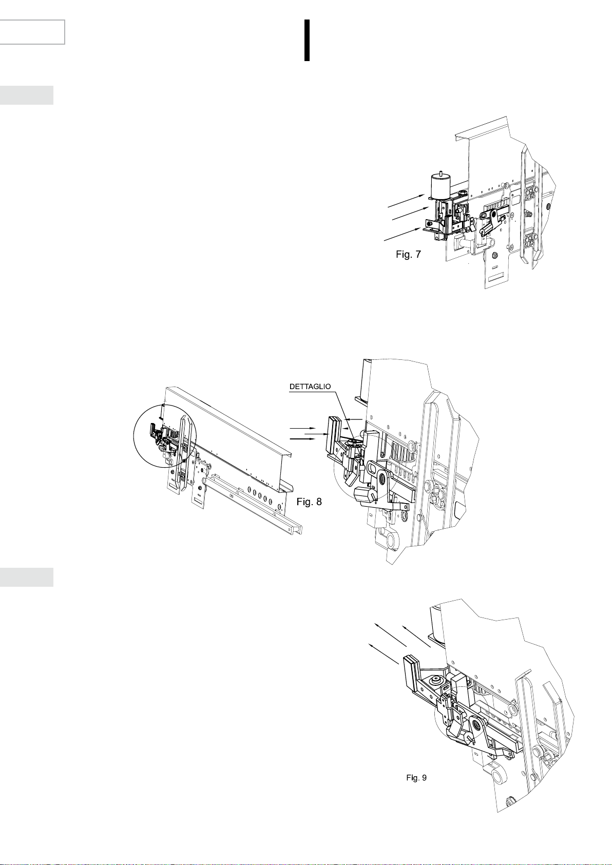
Keeping the trolley against the rubber block, push the lock device against
the housing and – while keeping it still – pull the pulley, thus giving
a medium tension to the belt. You can now tighten the nut to torque
(Figure 7).
Check the manual operation of the lock, lever in the direction of the arrows to make sure that the lock lever has some
clearance within the slot of the hooking lever mounted on the trolley (Figure 8).
If - when the manual operation is being checked- the lock lever collides
with the hooking one instead of within the slot, loosen again the nut
which was previously tightened, move the lock further away in order to
enable the correct hooking to the trolley, and repeat the adjustment of
the belt take-up as mentioned above (figure 9).
Carry out some manual openings and closings of the wing for safety,
in order to ascertain the mating between the block lever and the one
which hooks on the trolley. Furthermore, check – with the hooking lever
closed – if the wing can lock even in case of collision to the trolley.

10
10 11
EN
S6
S7
Once the correct operation of the systems is ascertained, proceed with the assembly of the manual release system.
The whole release system is supplied pre-assembled and packaged separately. The only thing to do to assemble it is
attaching the thimble by bolt and nut into the hole at the extremity of the lever as shown in Figure 10.
Attach then the bracket to the trolley trying to keep the spring in thrust as it is sufficient to facilitate the return after op-
eration.
To assemble the releasing device at the floor, you will find two holes on the upper bracket of the upright (rebate side)
which shall be used to assemble a kit supplied with the doors (as per Figure 11, otherwise refer to Figure 12).
Once the magnet support bracket is attached, align the car to the floor and move slowly closer to the magnet located on
the operator lock lever until – by opposition of the magnets – the lever releases the trolley. Tighten then the bolts for the
adjustment of the bracket, since the lock is now aligned.

12
EN
12 13
S8
If the lock device is requested for existing systems, there most likely will be no holes on the floor door bracket. Two holes
are therefore to be drilled as shown in Figure 12.

1212 13
D
Die Victory Türsperre kann an allen 2AT-Türen ?[operatori sind hier wohl Türen?, ) (Teleskopflügel) montiert werden, s.
Abb. 1, ohne große Änderungen vornehmen zu müssen.
MONTAGEANLEITUNG FÜR ZWISCHENETAGEN-TÜRSPERRE
Um Zugang zum Laufwagen zu erhalten, müssen zunächst die 4 Schrauben gelöst werden, mit denen das Kupplung-
selement am Laufwagen befestigt ist, s. Abb. 2.
Befestigen Sie den Kupplungshebel einschl. Handentriegelung am Laufwagen an den beiden zusammenfallenden
Bohrungen, s. Abb. 3, unter Verwendung der zwei Schrauben M6 und dazugehörigen Muttern aus dem mitgelieferten
Sperrschraubenset.
S2
S1

14
D
14 15
S3
Nach Befestigung des Kupplungshebels am Laufwagen ist das Kupplungselement wieder an den Laufwagen zu mon-
tieren, s. Abb. 4; das Maß (x) 13 mm muss eingehalten werden.
Lösen Sie die Mutter an der Riemenscheibe und halten die diese dabei mit einer Hand fest, so dass sie nicht herunter
fällt und sich der Riemen nicht vom Sitz löst, s. Abb. 5.
Setzen Sie die Sperrvorrichtung ein und schrauben Sie sie im Gewindeschaft der Riemenscheibe fest. Anschließend
setzen Sie die vorher entfernte Unterlegscheibe und Mutter in die Buchse, ziehen die Einheit jedoch noch nicht fest an,
s. Abb. 6.

14
14 15
D
S4
S5
Nun halten Sie den Laufwagen gegen das Gummistück im Anschlag und
schieben die Sperrvorrichtung in den Anschlag gegen das Gehäuse.
Halten Sie sie fest und ziehen die Riemenscheibe, so dass der Riemen
gespannt wird (mittlere Spannung). Jetzt kann die Mutter fest angezogen
werden, s. Abb. 7.
Anschließend wird der manuelle Betrieb der Sperrvorrichtung überprüft. Bei Verwendung? in Pfeilrichtung muss über-
prüft werden, ob der Sperrhebel mit einem geringfügigen Spiel im Langloch des Kupplungshebels am Laufwagen arbe-
itet, s. Abb. 8.
Stößt während der Überprüfung der manuellen Betriebs der Sperrheb-
el mit dem Kupplungshebel und nicht in dem Langloch zusammen,
muss die vorher angezogene Mutter wieder gelöst und die Sperrvor-
richtung entfernt werden, so dass sie richtig an den Laufwagen ankup-
pelt. Anschließend die Riemenspannung wieder einstellen, wie oben
dargestellt, s. Abb. 9.
Detail
Zur Sicherheit öffnen und schließen Sie die Tür einige Male manuell,
um zu prüfen, ob der Sperrhebel und der Kupplungshebel am Laufwa-
gen einkuppeln. Prüfen Sie außerdem bei geschlossenem Kupplung-
shebel, ob im Fall einer Störung der Zusammenstoß mit dem Laufwa-
gen auf jeden Fall die Tür sperrt.

16
D
16 17
S6
S7
Nachdem der einwandfreie Betrieb des Systems festgestellt wurde, kann mit der Montage der manuellen Entriegelung
begonnen werden. Das Montagekit für die Entriegelung wird in einem Plastikbeutel geliefert und ist schon vormontiert.
Zur Montage muss nur das Seilende und Schlaufe mit Schraube und Mutter in der Bohrung am Ende des Hebels bef-
estigt werden, s. Abb. 10.
Anschließend befestigen Sie den Haltewinkel am Laufwagen. Versuchen Sie dabei die Feder nur so weit wie nötig ge-
drückt zu halten, um den Rücklauf nach der Betätigung zu erleichtern.
Zur Montage der Etagen-Entriegelung finden Sie zwei Bohrungen an dem oberen Bügel des Türflügelschenkels in An-
schlagrichtung vor, die für die Befestigung eines im Lieferumfang der Tür enthaltenen Montagekit vorgesehen sind, s.
Abb. 11, (falls nicht, s. Abb. 12)
Nach Befestigung der Magnethalterung richten Sie die Fahrstuhlkabine am Etagenboden aus und nähern sich langsam
dem Magneten am Sperrhebel der Türsperre, bis der Hebel durch das Gegenüberliegen der Magnete den Laufwagen
auskuppelt. Da das Sperrsystem jetzt ausgerichtet ist, können Sie die Schrauben für die Bügeleinstellung anziehen.

16
16 17
D
S8
Wurde die Entriegelung für schon vorhandene Anlagen bestellt, kann es sein, dass keine Bohrungen am Bügel der
Etagentür vorhanden sind. In diesem Fall fertigen Sie 2 Bohrungen gem. Angaben in Abb. 12 aus.

18
F
18 19
Le Verrouilage Porte Victory peut être monté sur toutes les portes opérateur 2T (à ventaux téléscopiques) comme dans
la Figure 1 sans qu’il soit nécessaire d’exécuter de modifications importantes.
GUIDE A L’ASSEMBLAGE DU VERROUILLAGE PORTE HORS ETAGE
Tout d’abord, il faut dévisser les 4 vis qui fixent le dispositif d’accouplement au chariot (Figure 2) afin d’avoir accès au
chariot même.
Fixer le levier d’accrochage, qui comprend le décrochage manuel du chariot, sur les deux trous correspondants (Figure
3) à l’aide de deux vis M6 et relatifs écrous fournis dans le prêt-à-monter de fixation du verrouillage.
S2
S1

18
18 19
F
S3
Une fois que le levier d’accrochage est fixé au chariot, remonter le dispositif d’accouplement à chariot même (Figure 4),
gardant la cote (a) à 13 mm.
Relâcher l’écrou qui attache la poulie, tout en tenant la poulie même d’une main afin d’éviter qu’elle tombe et que la
courroie sorte de son siège, comme il est indiqué à la Figure 5.
Introduire le dispositif de verrouillage et le fixer à l’intérieur de la douille à pas de vis de la poulie. Introduire par la suite
la rondelle et l’écrou qui avaient été préalablement enlevés, sans serrer au couple final (Figure 6).

20
F
20 21
S4
S5
Tout en gardant le chariot contre le caoutchouc, presser le verrou contre
le siège, et – le gardant en position – tirer la poulie, donnant ainsi une
tension moyenne à la courroie. L’on peut maintenant serrer l’écrou au
couple final (figure 7).
Vérifier lo fonctionnement manuel du verrou, fair levier dans la direction des flèches pour s’assurer que le levier de ver-
rouilage ait du jeu à l’intérieur de la boutonnière du levier d’accrochage monté sur le chariot (Figure 8).
Si – lorsque l’on vérifie le fonctionnement manuel – le levier de ver-
rouilage est en collision avec celui d’accrochage au lieu qu’à l’intérieur
de la boutonnière, relâcher à nouveau l’écrou qui avait été serré au-
paravant, éloigner le verrou afin de permettre le bon accrochage au
chariot, et répéter l’opération de réglage de la courroie qui est décrite
ci-dessus (Figure 9)
Exécuter quelques ouvertures et fermetures manuelles du vantail pour
des raisons de sécurité, afin de vérifier l’accouplement entre le levier
de verrouillage et celui d’accrochage au chariot. Verifier aussi – le
levier d’accrochage fermé - si le vantail est verrouilé aussi au cas de
collision avec le chariot.
Table of contents
Languages:
Popular Door Lock manuals by other brands

LOCKLY GUARD
LOCKLY GUARD DEFENDER SLIDE EDITION installation guide

Alarm Lock
Alarm Lock Trilogy PDL6500 Programming instructions

Schlage
Schlage Connect BE469ZP quick start guide

Passtech
Passtech HP100 user guide

Signature Hardware
Signature Hardware GRIGGS 946757-DU manual

Siegenia
Siegenia KFV BS 2100 Assembly instructions