Victron energy 25A Buck-Boost DC-DC converter User manual

Manual
EN
Manual
ES
Manuale
IT
Manual
PT
Kılavuz
TR
Appendix
Buck-Boost DC-DC Converter
25A / 50A / 100A


1
EN ES IT PT TR Appendix
Introduction
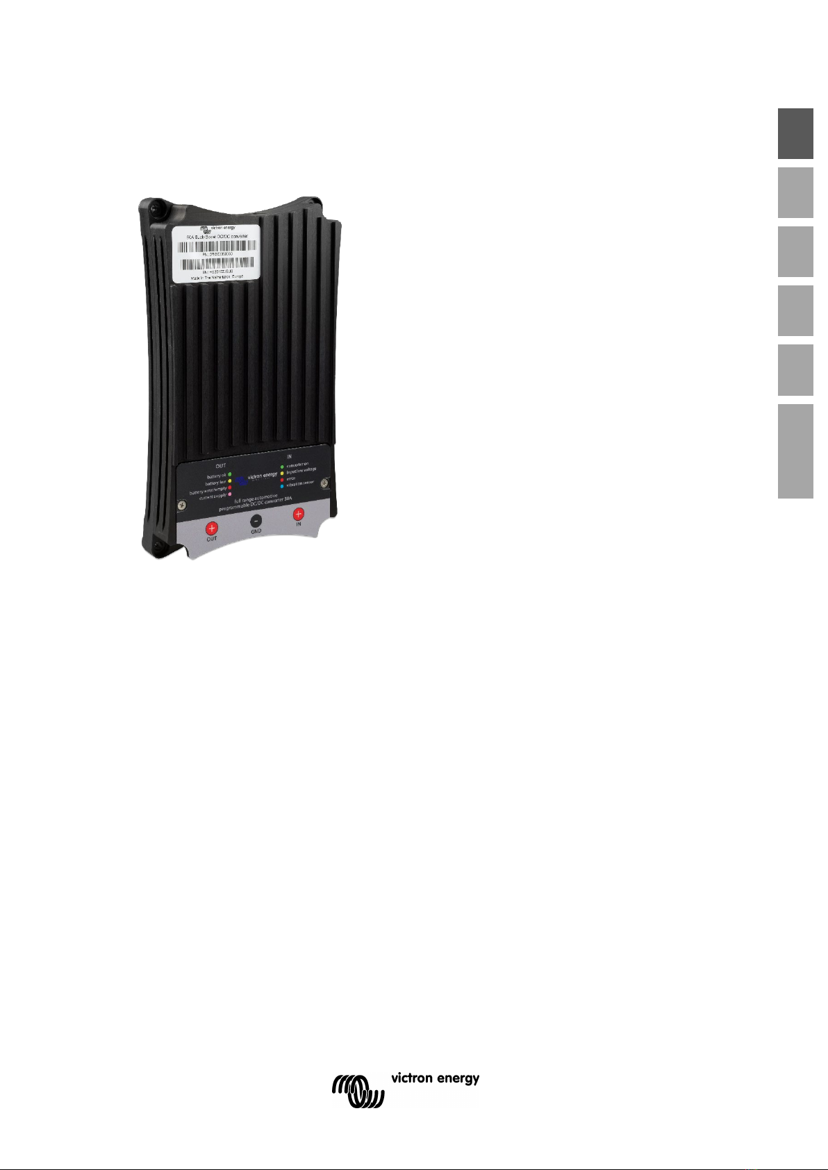
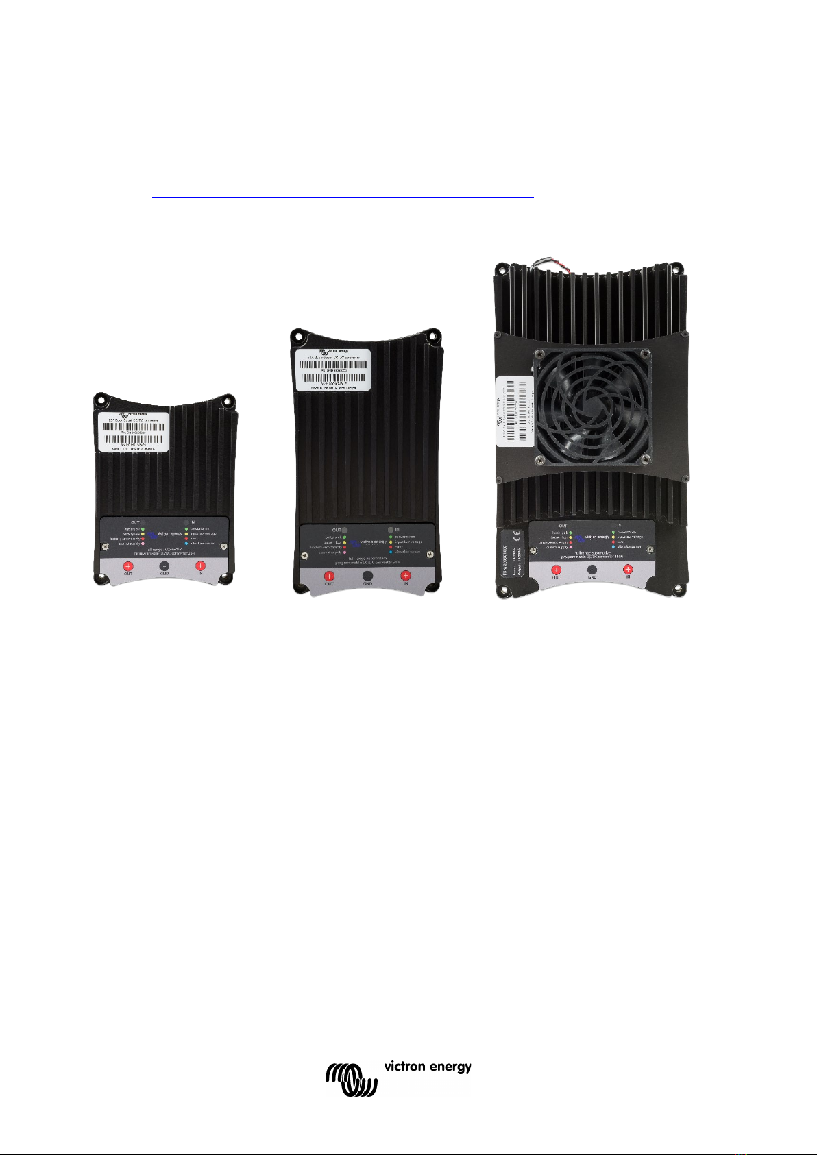
Full range programmable DC/DC converter 25/50/100A.
The solution for battery charging problems with Euro 5 and Euro 6 engines and alternator charge current
protection with lithium systems.
General description:
The Buck-Boost converter series is a program of specially developed DC/DC converters for fully-controlled charging
of an extra battery or a battery bank. Application is necessary in the case of vehicles with an alternator intelligent
control, and for general protection of the alternator in lithium systems.
Alternators of Euro 5 and 6 engines, which are controlled by the onboard electronics, often supply too low charging
voltage even with the engine running. As a result, a Buck-Boost converter is necessary to charge the extra battery. In
the case of lithium systems, the alternator must be protected against overload, resulting in overheating, which arises
because the voltage control of the alternator cannot anticipate zero resistance of lithium battery systems.
To ensure that the start battery of the vehicle is always loaded with priority, the units of Buck-Boost series will only
provide power when the engine is running. This is possible thanks to the built-in engine running detection and the
related programmable time-delayed switching. This also prevents the onboard voltage of the vehicle from becoming
too low. It is not necessary to intervene in the system of the vehicle, install a separate motor run sensor or intervene
in the CAN bus system. Apart from this detection, the Buck-Boost series equipment can also be switched on with a
programmable input.
The Buck-Boost series is fully programmable through a very simple and easy PC application. The output current has
an automatic limitation that is adjustable. The automatic stop becomes active as soon as the temperature comes
close to a pre-set maximum.
The output voltage is fully adjustable and is independent of the input voltage due to the automatic Buck-Boost control.
This control also ensures that the current will never exceed the set value. Also not when the input voltage is higher
than the output voltage.
Applications:
•Charging an extra/second battery (bank) with an eco
alternator of a Euro 5 or Euro 6 engine.
•Charging lithium batteries with an alternator without
temperature protection.
•Automatic activation and deactivation of the
alternator charge current, based on a unique engine
running detection protocol.
General features:
•Buck-Boost converter is fully programmable
•Input voltage 10..30 Vdc
•Output voltage 10..30 Vdc
•Output current (max.at 12V) 25, 50 or 100A
•Output current (max.at 24V) 12.5, 25 or 50A
•Adjustable current limiter
•Automatic activation when engine running
•Output for activation/deactivation of loads
•Battery temperature monitoring (optional)
•LED status indicators
•M8 connections
•USB for configuration/monitoring
•CAN-bus for control purposes and CAN-bus Temp
Sensor communication
•Battery monitor

2
The Buck-Boost range is fully programmable by means of a Windows application – TSConfig – that is very simple and
intuitive to use.
TSConfig.
We recommend updating your TSConfig program regularly so that you always have the latest version. Updates are
available at https://www.victronenergy.com/support-and-downloads/software
25A
50A
100A

3
EN ES IT PT TR Appendix
Warnings
Read this manual carefully before installing and commissioning the equipment.
Store the manual carefully and pass it on to a new user of this product!
Explanation of the symbols used
DANGER!
Safety instruction:
Failure to comply will result in death or serious
injury.
WARNING!
Safety instruction:
Failure to comply may result in death
or serious injury.
CAUTION!
Failure to do so may result in property damage
and limit the
functionality of the product.
INSTRUCTION
Additional information for operating the
product.
General safety instructions
The manufacturer cannot be held liable for damage in the following cases:
• mounting or connection errors
• product damage by mechanical impacts and overvoltage
• modifications of the product without the express permission of the manufacturer
• use with purposes other than those described in the manual
For safety reasons when installing and using electrical appliances, always observe the risks of electric shock, fire risk
and injury!

4
General safety
DANGER!
Use a fire extinguisher suitable for electrical appliances in the event of a fire. Always have a
fire extinguisher at hand in the premises and use it appropriately.
WARNING!
•Use the equipment only according to the instructions.
•Make sure that the plus (+) and minus (-) poles never touch each other.
•Disconnect the product from the battery when:
– performing cleaning and maintenance
– replacing a fuse (only by specialists)
•for disassembly of the product:
– Disconnect all connections.
– Ensure that all inputs and outputs are energized.
•If the product or connecting cable is visibly damaged, the product should not be put
into operation.
•If the connection cable of this product is damaged, it must be replaced by a qualified
personnel.
•Repairs to this product may only be performed by the manufacturer. Improper repairs
can lead to considerable hazards.
•This product must not be used by children and by persons with reduced physical,
sensory or mental abilities or lacking necessary experience and knowledge. Users
should have insight into the dangers that the use of the product entails.
•Electrical appliances are not toys. Store and use the product for this reason out of
reach of children, and ensure that children do not play with the product.
CAUTION!
•Before commissioning, ensure that the set voltage of the product corresponds to the
system voltage of the existing energy supply.
•Pay attention that other objects cannot cause a short circuit at the contacts of the
device.
•Store the product in a dry and cool place.
Safety when assembling the product
DANGER!
Do not mount the product in places where there is a risk of a gas or dust explosion.
WARNING!
Provide a stable mounting!
The product must be securely mounted and attached to prevent it falling, dropping, and
preventing contact of the connections with surrounding objects.
CAUTION!
•Do not expose the product to heat sources (solar radiation, heating, etc.).
•Avoid additional heating of the product.
•Install the product in a dry place protected against splashing water.

5
EN ES IT PT TR Appendix
Safety at the electrical connection of the product
DANGER!
Risk of fatal electric shock!
•When working on the electrical system, make sure that someone is around who can
help in case of an emergency.
•When installing on boats: Improper installation of electrical appliances on boats can
cause corrosion damage to the boat. Have the product connected by a qualified
electrician.
WARNING!
•Provide a sufficient cable intersection.
•Mount the cables so that they cannot be damaged by doors or hoods. Crushed
cables can lead to life-threatening situations, and should be replaced.
•Install the cables in such a manner that they cannot be tripped over, and any damage
to cables is excluded.
CAUTION!
•Use wire conduits if cables are to be routed through sheet walls or other feedthroughs
with sharp edges.
•Do not combine an AC cable and DC cable in the same channel (wire conduit).
•Do not loosen the conduits or sharply kink them.
•Attach the cables with the right materials and tools.
•Never pull the cables, take sufficiently long cable lengths of sufficient intersection in
relation to its length.
Safe use of the product
WARNING!
If the product is used in environments with lead-acid batteries, the room should be well
ventilated. Explosive hydrogen gas is released from these batteries, which can be ignited by
electric sparks.
CAUTION!
•Do not use the appliance
– in a salt-containing, damp or wet conditions
– nearby aggressive vapours
– near flammable materials
– in explosive environments
•Before use, check that the cables and connections are dry.
•Always disconnect the power supply when working on the product.
•Parts of the product may still be energized after the product has been disconnected.
•Do not disconnect cables when the product is still in use.
CAUTION!
•Prevent the product from being covered or being installed in a space that is too small.
•Provide proper ventilation.

6
Safety when handling batteries
WARNING!
Batteries may contain harsh and corrosive acids. Avoid any and all physical contact with the
battery fluid. In case of skin contact with battery fluids, wash the affected areas of the skin with
water.
In case of injuries due to acids, please be sure to consult a physician.
CAUTION!
•When working with batteries do not wear metal objects such as watches or rings.
•Lead-acid batteries can cause short-circuit currents that can lead to serious burns.
Risk of explosion!
•Wear protective goggles and safety clothing when working on batteries. When
working with batteries, do not touch your eyes .
•Do not smoke and make sure there are no sparks nearby the engine or the battery.
•Do not attempt to charge frozen or defective batteries. In this case, place the battery
in a frost-free room and wait until the battery is at ambient temperature. Then start the
loading procedure.
CAUTION!
•Use only rechargeable batteries.
•Use sufficient cable intersections.
•Secure the positive cable with a fuse.
•Prevent metal parts from falling on the battery. This may result in sparks or short-
circuiting of the battery and other electrical parts.
•Pay attention to the correct polarity when connecting.
•Please observe the battery and equipment manufacturers’ instructions listed in
corresponding manuals.
•In case the battery needs to be removed, always disconnect the ground connection
first. Then disconnect all other connections and disconnect all consuming points from
the battery before removing it.

7
EN ES IT PT TR Appendix
Connection
Simplified diagram: Connections:
OUT
GND
IN
IN : Converter
input
(alternator/starter battery)
GND : GND (chassis)
OUT : Converter output (extra battery)
Pin 1 : Input/output (purple wire)
Pin 2 : Input/output (green wire)
When Pin 1 or Pin 2 is being used, use the resistors
supplied to ensure safety.
This is no longer necessary in the most recent models
(recognisable by their ridged housing).
Microcontroller
Buck-Boost controllers
Sensor
3-axis
1 in/out
2 in/out
temp
Relay driver
Converter
output
GND
Converter
input
CAN.Bus connection
USB connection
OUT
GND
IN

8
OUTPUT led indicator
INPUT led indicator
LED indicators
The Buck-Boost DC-DC converter is equipped with two RGB LEDs.
The IN LED has the following functions:
Green: The converter is switched on (by the engine running detection, or by applying a voltage on pin 1).
Yellow:The input voltage is lower than the set threshold to allow the converter
to switch on.
Red: The internal temperature is higher than the set safety threshold. The converter is
switched on
Blue: Short light pulses = the engine running detection is active, the converter turns on after a delay.
Flashes slowly = the converter is switched off and blocked for switching on due to
A too low input voltage.
The OUT LED has the following functions:
Green: The converter is switched off. The connected battery has a correct terminal voltage.
Yellow:The converter is switched off. The connected battery has too low a terminal voltage.
Red: The converter is switched off. The connected battery is empty or the battery is not connected.
Purple: The converter is switched on and supplies power to the connected battery and/or electrical
consuming points.
Flashing purple: The converter is switched off. When the converter starts up, the set voltage of the
second battery is too low (safety circuit 31 is active).
The normal alerts of each LED blinks slowly for power saving (Setting 27).
Engine running detection
The converter has a unique engine running detection in order to be able to detect a running vehicle
engine. This prevents the converter from charging the starter battery if the alternator does not supply
power.
The converter is switched on:
When the engine is running and the supply voltage is >= (adjustable) volts and any (adjustable) minute
blocking is over.
Pin 1 input (as an alternative to the engine running detection)
The converter may also be switched on with a switch or relay contact.
Switch on:
The converter is switched on:
If pin 1 input >= 2 volts, and the supply voltage is >= (adjustable) volts and any blocking is over.
Important when installing!
Basic settings
At the time of commissioning, the following basic settings shall be applied:
Setting 12V – 12V 24V – 24V 12V – 24V
20 Output voltage 14.4V 28.8V28.8V
22 Maximum output current
60% of the current supplied by the vehicle’s alternator (max.)
24 Undervoltage threshold 11.8V – 12.2V 23.8V – 24.2V11.8V – 12.2V

9
EN ES IT PT TR Appendix
On-board voltage
The on-board voltage under setting 24 of the TS Config software shall not be set too low. This value may
be adjusted by a qualified electrician only!
Input and output fuse
Use the following input and output fuse and cable intersection depending on the Buck-Boost type:
12 VOLTS INPUT
Buck-Boost type
Fuse value / Ampères
Cable thickness (< 5 metres)
25A
40 Ampère (A)
16 mm2
50A *)
60 Ampère (A)
35 mm2
100A *)
125 Ampère (A)
50 mm2
12 VOLTS OUTPUT
Buck-Boost type
Fuse value / Ampères
Cable thickness (< 5 metres)
25A
40
Ampères (A) 16 mm2
50A *)
60 Ampères (A)
35 mm2
100A *)
125 Ampères (A)
50 mm2
24 VOLTS INPUT
Buck-Boost type
Fuse value / Ampères
Cable thickness (< 5 metres)
25A
30 Ampères (A)
16 mm2
50A *)
40 Ampères (A)
35 mm
2
100A *)
80 Ampères (A)
50 mm2
24 VOLTS OUTPUT
Buck-Boost type
Fuse value / Ampères
Cable thickness (< 5 metres)
25A
30 Ampère (A)
16 mm2
50A *)
40 Ampère (A)
35 mm2
100A *)
80 Ampère (A)
50 mm2
*) CAUTION. In order to use the 50A or 100A, the alternator must have sufficient charging capacity to be able to
supply the maximum input voltage that the converter requires. For details, please see the input voltage (max.) in
the table.
Connection
First connect all GND cables to the converter, the battery and the chassis, and then only the positive (+) cable.
This is important because in the converter everything refers to GND.
When the two plus (+) cables are connected without GND, the potential difference between the plus (+) connections
ensures uncontrolled and unsecured currents!
Always check that the GND connection on the middle M8 connection is correctly connected.
The converter has no reverse polarity protection!
Converter operation
The Buck-Boost DC-DC converter operates on the principle of buck-boost.
This means that the input voltage may be both higher and lower than the set output voltage. The amount
of the charge current remains in both situations always fully under control.
A brief overview of possible conversions:
Buck-Boost type
1
2V – 12V Default
24V
– 24V Default
12V
– 24V Default
25A charging current max.
25A
15A
10A
50A charging current max.
50A
25A
20A
100A charging current max.
100A
50A
50A

10
Charging current limiter
The output current is determined by the following factors:
Setting: The maximum desired charging current is set via the USB connection
(with the Windows application TSConfig).
Temperature: If the converter temperature comes close to the set maximum temperature, the charging
current is automatically limited. As a result, the temperature of the Buck-Boost inverter is
never inadmissibly high.
TSConfig application
The Buck-Boost converters can be configured extensively with TSConfig software. This software also includes a
monitor window, where real-time operation of the converter can be tracked.
The following image shows a screenshot of the TSConfig software:
The TSConfig software and manual can be downloaded from: https://www.victronenergy.com/support-and-
downloads/software
Wiring diagram
Starter
Battery
Service battery
Alternator
50A
100A

11
EN ES IT PT TR Appendix
CAN-bus Temp Sensor
The CAN-bus Temp Sensor is an accessory that is specially developed for all types of Buck-Boost converter.
The temperature is transmitted to the converter via the CAN-bus communication ports by means of a communication
cable. The CAN-bus Temp Sensor can also be used in combination with any Victron Multi or Quattro. This enables the
charging voltage to be regulated if the temperature is too low.
In LiFePO4 lithium systems, this sensor is needed in many system applications, because LiFePO4 batteries must not be
charged up when they are too cold. Charging lithium batteries when they are near or below freezing point will cause
permanent damage to the cells.
The CAN-bus Temp Sensor is a Buck-Boost accessory and must be ordered separately.
The 25A does not have a CAN connection, which means that the CAN-bus Temp Sensor cannot be used.
Wiring diagram
Starter Battery
50A
100A

12
Technical specifications
Buck-Boost DC-DC
Converter
25A 50A 100A
Input voltage range
10 to 30 Volt
Threshold undervoltage
10V
Output voltage range
10-30V
Maximum charging current
12V : 25A 24V : 15A
12V : 50A 24V : 25A
12V: 100A 24V: 50A
Power consumption
Converter switched off, LEDs
from energy saving mode)
7mA
Input voltage on/off (pin 1, purple wire)
Threshold voltage ‘On’
> 2V
Maximum input voltage
30V
Output pin 1 and pin 2
Output voltage as enabled
Vpinout = Vin
Maximum voltage (per pin)
Ipinout = 1.5A
GENERAL
Operating temperature range
-25...+60°C
Ambient temperature
Max power at 40°C
Weight
0.6 kg
1.4 kg
4.1 kg
Dimensions
165 x 120 x 30 mm
213 x 120 x 30 mm
288 x 162 x 95 mm

1
EN ES IT PT TR Appendix
Introducción
Convertidor CC/CC de 25/50/100A totalmente programable.
La solución a los problemas de carga de baterías con motores Euro 5 y Euro 6 y protección de corriente de
carga para alternadores con sistemas de litio.
Descripción general:
La serie de convertidores Buck-Boost es un conjunto de convertidores CC/CC especialmente desarrollados para la
carga totalmente controlada de una batería adicional o de una bancada de baterías. Su aplicación es necesaria en el
caso de vehículos con control inteligente del alternador y para la protección en general del alternador en sistemas de
litio.
Los alternadores de motores Euro 5 y 6, controlados por la electrónica de a bordo, a menudo suministran una
tensión de carga demasiado baja incluso cuando el motor está en marcha. El resultado es que se necesita un
convertidor Buck-Boost para cargar la batería adicional. En el caso de sistemas de litio, el alternador debe
protegerse contra la sobrecarga, que puede dar como resultado un sobrecalentamiento, debido a que el control de
tensión del alternador no puede prever la resistencia cero de los sistemas de baterías de litio.
Para garantizar que la batería de arranque del vehículo se carga prioritariamente, las unidades de la serie Buck-
Boost solo suministrarán energía cuando el motor esté en marcha. Esto es posible gracias al detector de motor en
marcha que incorpora y al conmutador de acción retardada programable correspondiente. Esto también evita que la
tensión de a bordo del vehículo baje demasiado. No es necesario intervenir en el sistema del vehículo, instalar un
sensor de marcha del motor por separado o intervenir en el sistema CAN bus. Aparte de esta detección, el equipo de
la serie Buck-Boost también puede activarse con una entrada programable.
La serie Buck-Boost es totalmente programable mediante una aplicación muy sencilla y fácil de usar. La corriente de
salida dispone de una limitación automática ajustable. La desactivación automática ocurre tan pronto se acerque la
temperatura al máximo preestablecido.
La tensión de salida es totalmente ajustable e independiente de la tensión de entrada, gracias al control Buck-Boost
automático. Este control también garantiza que la corriente nunca exceda el valor establecido. Tampoco cuando la
tensión de entrada sea superior a la tensión de salida.
Aplicaciones:
•Carga de una batería (o bancada) adicional con un
eco alternador de un motor Euro 5 o Euro 6.
•Carga de baterías de litio con un alternador sin
protección de temperatura.
•Activación y desactivación automática de la corriente
de carga del alternador con un protocolo único de
detección de funcionamiento del motor.
Características generales:
•El convertidor Buck-Boost es totalmente programable
•Tensión de entrada 10..30 Vcc
•Tensión de salida 10..30 Vcc
•Corriente de salida (máx. a 12V) 25, 50 ó 100A
•Corriente de salida (máx. a 24V) 12,5, 25 ó 50A
•Limitador de corriente ajustable
•Activación automática con motor en marcha
•Salida para activación/desactivación de cargas
•Supervisión de la temperatura de la batería
(opcional)
•Indicadores LED de estado
•Conexiones M8
•USB para configuración/seguimiento
•Comunicación con CAN-bus para control y con
sensor de temperatura CAN-bus
•
Monitor de baterías

2
La gama Buck-Boost se puede programar completamente a través de una aplicación de Windows – TSConfig – muy
intuitiva y fácil de usar.
TSConfig.
Le recomendamos que actualice su programa TSConfig regularmente para que disponga siempre de la última versión.
Puede encontrar las actualizaciones en https://www.victronenergy.com/support-and-downloads/software
25A
50A
100A

3
EN ES IT PT TR Appendix
Avisos
Lea este manual detenidamente antes de instalar y poner en marcha el equipo.
Guarde el manual en lugar seguro y páselo a cualquier nuevo usuario de este producto.
Explicación de los símbolos utilizados
¡PELIGRO!
Instrucciones de seguridad:
El incumplimiento podría provocar lesiones graves
o mortales.
¡AVISO!
Instrucciones de seguridad:
El incumplimiento podría provocar la muerte
o lesiones graves.
¡PRECAUCIÓN!
El incumplimiento podría provocar daños
materiales y limitar la
funcionalidad del producto.
INSTRUCCIONES
Información adicional para el funcionamiento
del producto.
Instrucciones generales de seguridad
El fabricante no se responsabiliza de daño alguno en los casos siguientes:
• errores de montaje o de conexión
• daños al producto provocados por impactos mecánicos y sobretensión
• modificaciones realizadas al producto sin autorización expresa del fabricante
• utilización con fines distintos a los descritos en este manual
Por motivos de seguridad, al instalar y utilizar aplicaciones eléctricas, tenga siempre en cuenta los riesgos de
electrocución, incendio y lesiones.

4
Seguridad general
¡PELIGRO!
En caso de incendio, utilice un extintor adecuado para aplicaciones eléctricas. Disponga
siempre de un extintor a mano en las instalaciones y utilícelo adecuadamente.
¡AVISO!
•Utilice el equipo exclusivamente según las instrucciones.
•Asegúrese de que los polos positivo (+) y negativo (-) nunca entren en contacto.
•Desconecte el producto de la batería cuando:
– Lleve a cabo su limpieza y mantenimiento
– Sustituya un fusible (sólo expertos)
•Para desmontar el producto:
– Desconecte todas las conexiones.
– Asegúrese de que todas las entradas y salidas están desenergizadas.
•Si el producto o los cables que lo conectan estuvieran visiblemente dañados, no
debería ponerse en marcha.
•Si el cable de conexión de este producto estuviera dañado, deberá ser sustituido por
personal cualificado.
•Cualquier reparación del producto deberá llevarla a cabo el fabricante Las
reparaciones inadecuadas podrían ser muy peligrosas.
•Este producto no debe ser utilizado por niños o por personas con capacidades
físicas, sensoriales o mentales limitadas, o por personas que carezcan del
conocimiento y experiencia necesarios. Los usuarios deberán ser conscientes de los
peligros inherentes a la utilización de este producto.
•Los aparatos eléctricos no son juguetes. Por ello, almacene y utilice el producto fuera
del alcance de los niños, y asegúrese de que estos no puedan manipularlo.
¡PRECAUCIÓN!
•Antes de su puesta en marcha, asegúrese de que la tensión del producto se
corresponde con la del sistema del suministro eléctrico disponible.
•Asegúrese de que ningún objeto pueda provocar un cortocircuito al entrar en
contacto con el dispositivo.
•Almacene el producto en un lugar seco y frío.
Seguridad al montar el producto
¡PELIGRO!
No monte este producto en lugares que presenten riesgo de explosión por gas o polvo.
¡AVISO!
¡Asegúrese de que el montaje sea estable!
El producto deberá montarse de forma segura y bien sujeto para evitar que se caiga y
evitando que las conexiones entren en contacto con objetos que se encuentren a proximidad.
¡PRECAUCIÓN!
•No exponga el producto a fuentes de calor (radiación solar, calefactores, etc.).
•Evite que el producto se sobrecaliente.
•Instale el producto en un lugar seco y protegido de salpicaduras.

5
EN ES IT PT TR Appendix
Seguridad de la conexión eléctrica del producto
¡PELIGRO!
¡Riesgo de descarga eléctrica mortal!
•Cuando trabaje en el sistema eléctrico, asegúrese de que hay alguien cerca que
pueda ayudar en caso de emergencia.
•Cuando se instale en embarcaciones: La instalación inadecuada de aparatos
eléctricos en barcos podría provocar corrosión en el mismo. Haga que el un
electricista cualificado conecte el producto.
¡AVISO!
•Utilice cables con una sección suficiente.
•Monte los cables de forma que no puedan verse dañados por puertas o capós. Unos
cables aplastados podrían resultar en amenazas vitales y deberán sustituirse.
•Instale los cables de tal forma que nadie pueda tropezarse con ellos ni dañarlos.
¡PRECAUCIÓN!
•Utilice canalizaciones si los cables tienen que ir a través de tabiques u otros
recorridos con bordes afilados.
•No ponga cables de CA y cables de CC en la misma canalización.
•No deje los cables demasiado sueltos o muy retorcidos.
•Sujete los cables con los materiales y herramientas adecuados.
•Nunca estire los cables, utilice cables con la longitud suficiente y con la sección
adecuada en relación con su longitud.
Uso seguro del producto
¡AVISO!
Si el producto va a utilizarse en un lugar que tenga baterías de plomo-ácido, este deberá estar
bien ventilado. Este tipo de baterías emiten gas de hidrógeno, que podría explotar de
producirse chispas eléctricas.
¡PRECAUCIÓN!
•No utilice el aparato
- En ambientes húmedos, mojados o con mucha presencia de salitre
- Cerca de vapores agresivos
- Cerca de materiales inflamables
- En entornos explosivos
•Antes de su uso, compruebe que los cables y las conexiones estén secas.
•Cuando trabaje en el producto, desconecte siempre la alimentación eléctrica.
•Algunas partes del producto podrían seguir energizadas después de desconectarlo.
•No desconecte el producto mientras esté siendo utilizado.
¡PRECAUCIÓN!
•Evite cubrir el producto, o instalarlo en un espacio demasiado pequeño.
•Procure que esté bien ventilado.

6
Seguridad al manipular las baterías
¡AVISO!
Las baterías pueden contener ácidos agresivos o corrosivos. Evite cualquier tipo de contacto
físico con el líquido de las baterías. En caso de que el líquido de la batería entre en contacto
con la piel, lave el área afectada con agua.
En caso de lesiones provocadas por ácidos, consulte sin falta a un médico.
¡PRECAUCIÓN!
•Cuando trabaje con baterías no lleve objetos metálicos, como relojes o anillos.
•Las corrientes de cortocircuito de las baterías de plomo-ácido pueden provocar
quemaduras graves.
¡Riesgo de explosión!
•Lleve gafas y ropa de protección cuando trabaje con baterías. No se toque los ojos
cuando trabaje con baterías.
•No fume y asegúrese de que no se produzcan chispas cerca del motor o de la
batería.
•No intente cargar baterías congeladas o defectuosas. En este caso, coloque la
batería en un lugar templado y espere a que la batería alcance la temperatura
ambiente. A continuación, inicie el procedimiento de carga.
¡PRECAUCIÓN!
•Utilice sólo baterías recargables.
•Utilice cables con la sección suficiente.
•Proteja el cable positivo con un fusible.
•Evite que caigan piezas metálicas sobre las baterías. Esto podría provocar chispas o
cortocircuitos en la batería y otras partes eléctricas.
•Asegúrese de la correcta polaridad de las conexiones.
•Siga las instrucciones del fabricante de la batería y del equipo, que encontrará en los
manuales correspondientes.
•En caso de que la batería deba retirarse, desconecte siempre la puesta a tierra en
primer lugar. A continuación, desconecte todas las conexiones y cargas
consumidoras de la batería antes de retirarla.
Other manuals for 25A Buck-Boost DC-DC converter
1
This manual suits for next models
2
Table of contents
Languages:
Other Victron energy Media Converter manuals

Victron energy
Victron energy 50A Buck-Boost DC-DC converter User manual

Victron energy
Victron energy Buck-Boost 100A User manual

Victron energy
Victron energy Orion-Tr User manual

Victron energy
Victron energy Orion 12/24-40 User manual

Victron energy
Victron energy ORI303100000 User manual

Victron energy
Victron energy 25A Buck-Boost DC-DC converter User manual

Victron energy
Victron energy VE.Net Blue Power Panel User manual