Videomitter MIT500 User manual

MIT500
2
© 2023 System Q Ltd
VideoMitter.com
Table of Contents
Introduction 3
User Information 3
Connections and Powering 4
Signal Transmission 6
Pairing 7
Multiple Pairs 8
Troubleshooting 9
Additional Antenna 11
Quick Links 12
Specifications 13
Conditions 14
General Company Disclaimer ....................................................................................... 14
WEEE Declaration ......................................................................................................... 14
Copyright ...................................................................................................................... 14

© 2023 System Q Ltd
3
Index
VideoMitter.com
Introduction
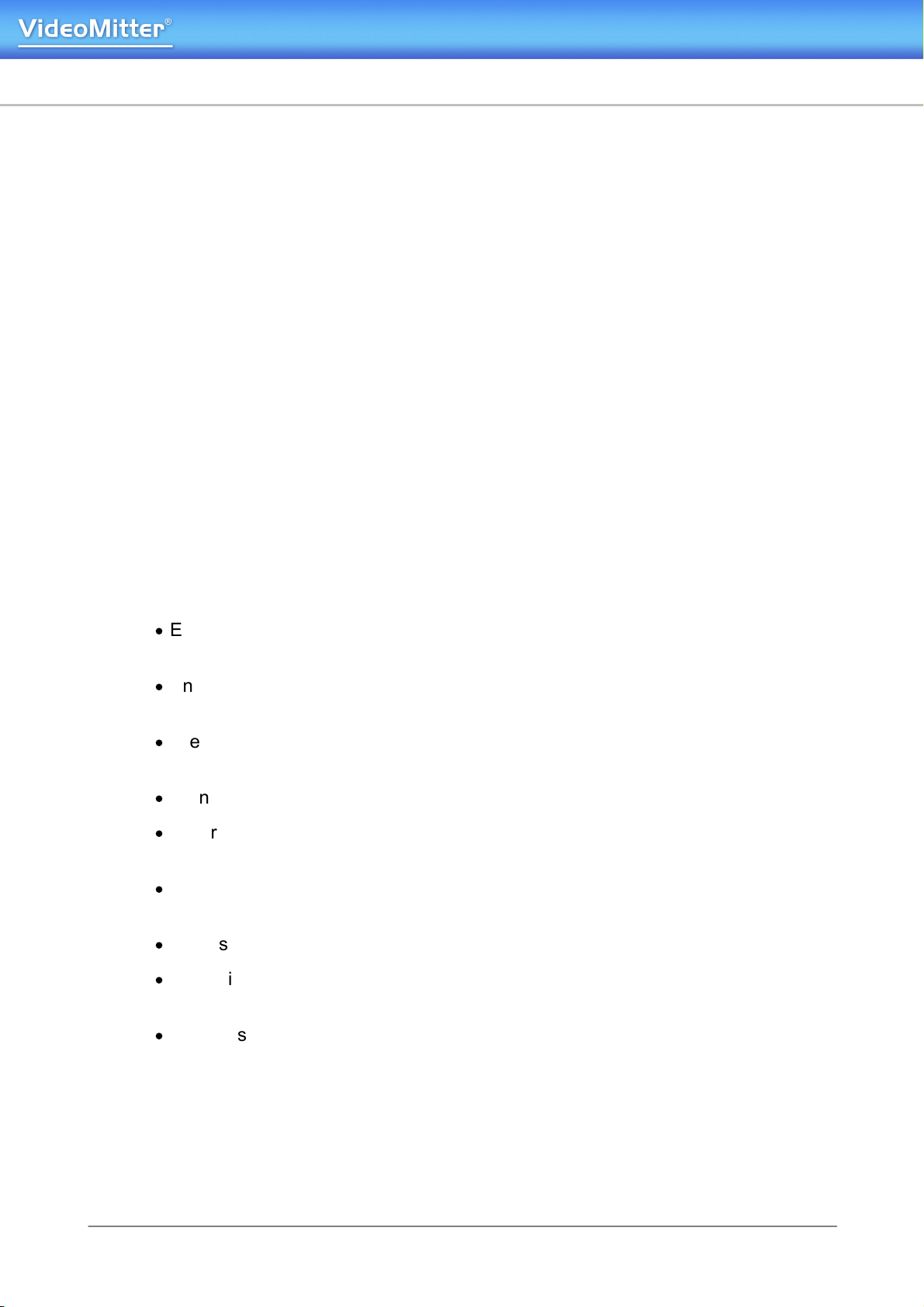
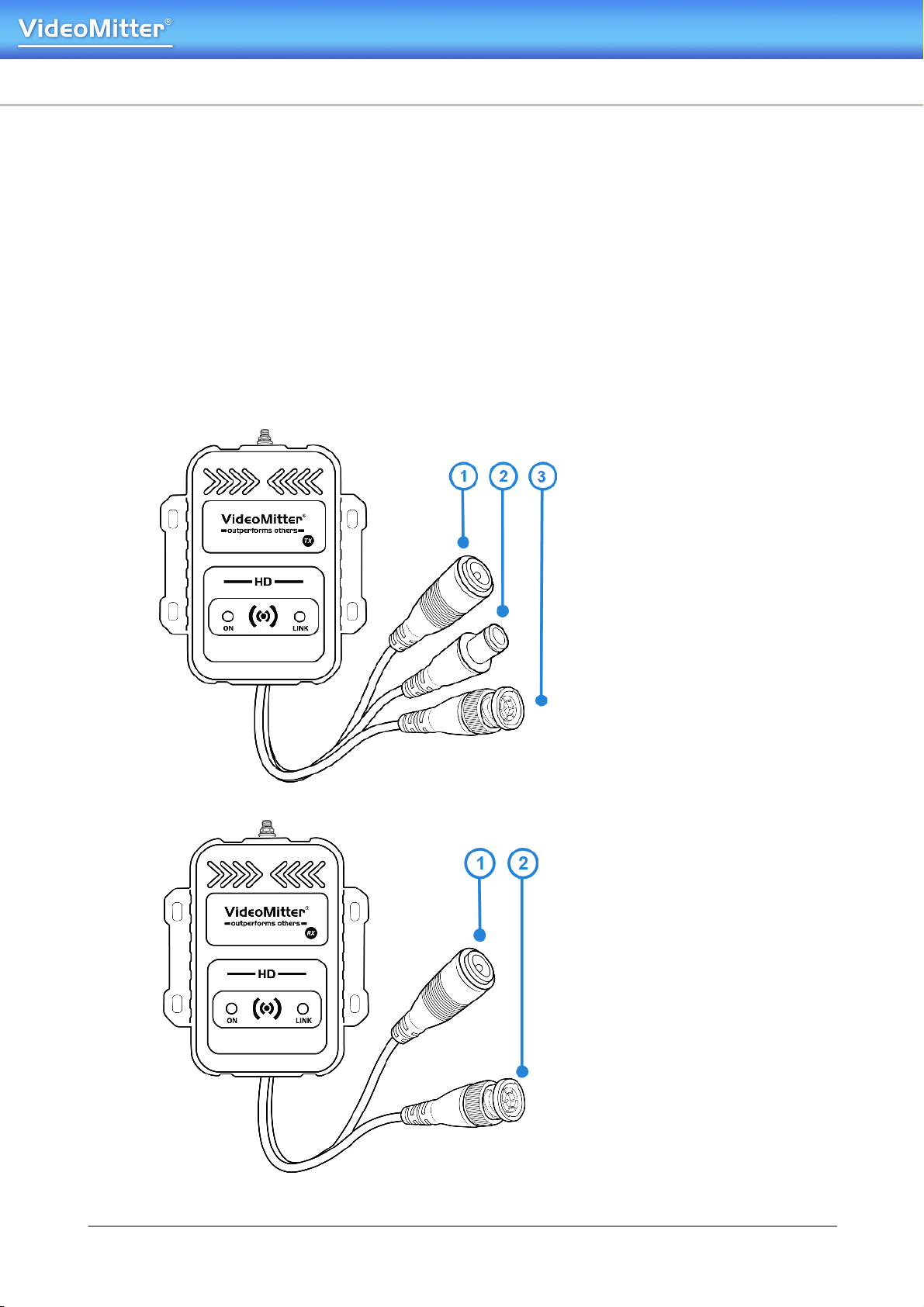
The 2MP HD MegaMitter can transmit one AHD CCTV camera wirelessly.
The MegaMitters are sold in pairs and one acts a transmitter and the other a receiver
for a one 2 one transmission.
For greater distances consider upgrading the antennas to directional ones which are
sold separately.
Up to 4 pairs of MegaMitters can be used on the same site but it is recommended to
use directional antennas when using multiple sets and keep them a minimum of 2m
apart.
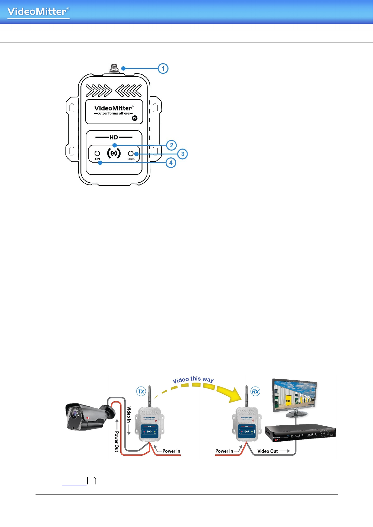
The MegaMitters require power from regulated 12V DC power supply.
Note: power supplies are sold separately.
User Information
·
Ensure the camera connected has a 4-in-1 selectable output set to AHD or have a
AHD video output (2MP).
·
Ensure the MegaMitters are installed in line of sight with no obstructions in between
the TX & RX.
·
The connections must be kept clean and dry, where they will not be exposed to high
temperatures, moisture or excessive dust.
·
Do not touch the product connections with wet hands.
·
Ensure the power is switched off if the product is not in use for a long period of
time.
·
There are no user serviceable parts in the product. Opening or attempting to repair
the product will void the warranty.
·
Only use a suitable regulated 12V DC power supply.
·
Do not install or use the device if the power cable or video connections are
damaged.
·
Do not use alcohol or solvents to clean the product, only clean using a damp cloth.

10/08/2023
4
MIT500
VideoMitter.com
Connections and Powering
Before installation it is recommended to connect the whole transmission
setup on a bench or local to the DVR / monitor. To ensure compatibility, and
that all parts are in working order.
Both the transmitter and receiver require a regulated 12V DC power supply
individually. When they are powered up a red power light will come on. The PSU for
the receiver and transmitter needs to be capable of supplying 12V D.C. @ 190mA
continuously as a minimum. (Not including the power out connection on TX for
powering a camera)
The Transmitter (TX) unit
has the following
connections:
1. 2.1mm 12V DC Power in
connection.
2. 2.1mm 12V DC power
out connection for power
pass-through so camera
and TX can share one
PSU.
3. Video in connection via a
BNC Lead.
The Receiver (RX) unit has
the following connections:
1. 2.1mm 12V DC power in
connection.
2. Video out connection via
a BNC Lead.

© 2023 System Q Ltd
5
Index
VideoMitter.com
Both units have the following:
1. Antenna Connection (RP
SMA Male Socket)
connects to extension
cables or direct connection
antenna models.
2. Pair Button.
3. Green Link Indicator LED.
4. Red Power Indicator LED.
Connecting Video
AHD 720p / AHD 1080p are the only compatible video input signals.
Connect the video input feed to the video BNC socket on the Transmitter.
Connect the video output feed to the BNC socket marked on the Receiver.
Powering a Camera
If the Transmitter (TX) power out connection for powering a camera is to be used,
then ensure the PSU is rated enough to power both the MegaMitter and the camera.
For Example; most eyeball cameras on average require 750mA. Combined with the
Transmitter this is roughly 950mA. Therefore a PSU rated a 12V D.C. @ 1.5A would
be recommended for the Transmitter and an eyeball camera. Other cameras may
require more current, so ensure the correct power rating is calculated.
To power a camera via power pass-through connect the power out cable (1) on the
transmitter to your camera’s power in female lead.
Note - If you press and hold the reset button you will need to re-pair the units, see
Pairing .
7

10/08/2023
6
MIT500
VideoMitter.com
Signal Transmission
Different site conditions will affect the signal transmission, and therefore will affect;
distance, range and performance of the MegaMitters.
In modern buildings sometimes the structure is
lined with “FOIL”. This can reflect or “ground” the
wireless signal, avoid transmitting through such.
If wiring is not an option then try mounting the
MegaMitter on the exterior of a building with the
connections in an ABS IP66 (waterproof) box.
When it is raining heavily microwave signals will
be absorbed by the rain and reduce the
distance it travels.
Keep the distance to a minimum between TX
and RX, or use directional antennas, see
Additional Antenna .
On some sites you may have other RF equipment that
can interfere with the MegaMitters.
Fitting directional antennas help “block” out the
interference, see Additional Antenna
Weather can affect transmission and reduce the
distance it travels.
Keep the distance to a minimum between TX
and RX, or use directional antennas, see
Additional Antenna .
Microwave signals will not go through hills, as
the densityof the hill absorbs the signal.
Ensure the MegaMitters are installed in line of
sight, avoid landscape obstacles and large
changes in elevation.
Allow for the use of directional antennas, see
Additional Antenna .
11
11
11
11

© 2023 System Q Ltd
7
Index
VideoMitter.com
Pairing
The MegaMitters are supplied bench tested, and pre-paired. Only one Receiver (RX)
can receive video from one Transmitter (TX), ensuring private secure connections.
When both the TX & RX are powered up and in within transmission range of each
other the green light will illuminate to indicate they are connected.
Pairing Process
As supplied the MIT500s are already paired, but if they do need pairing followthe
process below;
1. Connect AHD Video into the Tx. Connect 12V DC Power to both Tx and Rx. Press
the PAIR button down on the RECEIVER for 3 seconds. The Link LED will start
to flash.
2. A countdown will start for 30 seconds, then press and hold the PAIR button on
the TRANSMITTER until the link LED starts flashing.
3. Once pairing is complete both Link LEDs will display solid Green. If a monitor is
connected to the RECEIVER it will display a signal strength bar at the top left hand
corner of the display.

10/08/2023
8
MIT500
VideoMitter.com
Multiple Pairs
When installing it is good practice to keep the MegaMitters away from another
transmission devices including other MegaMitters. This is because interference can
cause poor performance which may result in intermittent loss of signal or non
operation.
The standard antenna that the
MegaMitters are supplied with is called
an “Omni-directional” antenna, this
means it transmits in “all” directions.
So when two transmitters are close to
each other they will be transmitting
signals at each other as well as the
receiver.
When using multiple pairs, keep the transmitters and receivers spaced apart. A
spacing of 1-2 metres is required between each transmitter, and the same between
each receiver.
It is recommended to use no more than 4 pairs per site to minimise any chance of
cross interference.
Don't install two transmitters close
together with omni directional antennas,
as the signal can cause distortion and
this can overwhelm the transmission
causing loss of signal.
Keep the MegaMitters at least 1-2
metres apart and add directional
antennas.

© 2023 System Q Ltd
9
Index
VideoMitter.com
Troubleshooting
No Video Signal displayed and the transmission signal
icon does not appear
This means there is no signal between the MegaMitters.
1. The wireless signal between the TX and RX is low,
meaning something is impeding the signal, stopping the
transmission - see Signal Transmission
2. The two devices are currently too far away from each other
with the current aerials.
3. Something is causing interference stopping the wireless
transmission between the two MegaMitters - see Signal
Transmission
4. The MegaMitters are not Paired, try the pairing process
again - see Pairing
No Video Signal is displayed but the transmission signal
is displayed
This means the wireless transmission between the two
MegaMitters is OK, but the input video signal is not
compatible or no video input signal is detected.
1. The video input signal is not being received by the TX.
Signal could be too low, or the camera is not powered.
2. The video input signal is not compatible. Check the signal
is AHD 720p / AHD 1080p.
Video is displayed in black and white / Corrupted Video
This means the video input signal is being detected by the
MegaMitter TX but is the wrong video format or the video
signal is too low.
1. The video input signal is not being received by the TX,
signal could be too low or no video is detected.
2. The video input signal is not compatible. Check the signal
is AHD 720p / AHD 1080p.
3. If a camera is also being powered from the same power
supply (at the TX), then the camera may require a separate
power supply to drive the camera and the MegaMitter.
6
6
7

10/08/2023
10
MIT500
VideoMitter.com
Flashing green Link LED
This means the MegaMitters units are not paired or there is no input video signal to
the TX unit.
1. The wireless signal between the TX and RX is low, meaning something is
impeding the signal, stopping the transmission - see Signal Transmission
2. The two devices are currently too far away from each other with the current
aerials.
3. Something is causing interference stopping the wireless transmission between
the two MegaMitters - see Signal Transmission
4. The MegaMitters are not Paired, try the pairing process again - see Pairing
5. The video input signal is not being received by the TX, signal could be too low or
no video is detected.
6. The video input signal is not compatible. Check the signal is AHD 720p / AHD
1080p.
Flashing red Power LED
This means the power supply does have enough power to drive the MegaMitter.
1. Check that the power light comes on when power is applied. Check the same at
both ends.
2. Disconnect video input or output connections as the video connection could be at
fault.
3. The issue could be related to voltage drop or the voltage being too low at the
MegaMitter.
4. The power supply may not be providing enough current output to the MegaMitter.
5. If a camera is also being powered from the same power supply (at the TX), then
the camera may require a separate power supply to drive the camera and the
MegaMitter.
Video loss at night
Not enough current supplied to the camera.
1. The issue could be related to voltage drop or the voltage being too low at the
MegaMitter.
2. The power supply may not be providing enough current output to the MegaMitter.
3. If a camera is also being powered from the same power supply (at the TX), then
the camera may require a separate power supply to drive the camera and the
MegaMitter.
6
6
7

© 2023 System Q Ltd
11
Index
VideoMitter.com
Additional Antenna
The antennas that are supplied with the MegaMitters are specified to work up to 200
metres with line of sight*, This range can be extended up to 1Km.
*Line of sight means no physical obstacles and the antennas can actually see each
other.
To see our full range of aerials please visit;
https://systemq.com/store/Category/Wireless-CCTV-Video-Antennas

© 2023 System Q Ltd
13
Index
VideoMitter.com
Specifications
Frequency
2.4Ghz
Video Format
AHD 720p / AHD 1080p
Range
200m (as supplied)
Max Range
Up to 1Km (with additional aerials)
Audio
No
IP Rating
IP65 (providing connections are made IP65)
Antenna
RP-SMA
Video Connection
BNC
Input Voltage
12V DC
Current Consumption
Tx 250mA Rx 140mA
Power Connection
2.1mm DC Socket
Operating Temperature
-30 ~ 70ºC
Delay
150mS Max
Modulation
16QAM/QPSK/BPSK
Transmission Channels
19 (FHSS – maximum 4 pairs per site
Pair separation distance
Minimum of 2m apart
Dimensions
110mm x 95mm x 25mm (Not including aerials or
wires)

10/08/2023
14
MIT500
VideoMitter.com
Conditions
11.1 General Company Disclaimer
All specifications are approximate. System Q Ltd reserves the right to change any
product specifications or features without notice. Whilst every effort is made to
ensure that these instructions are complete and accurate, System Q Ltd cannot be
held responsible in any way for any losses, no matter howthey arise, from errors or
omissions in these instructions, or the performance or non-performance of the
equipment that these instructions refer to.
11.2 WEEE Declaration
This symbol on the products and/or accompanying documents means that used
electronic equipment must not be mixed with general household waste. For
treatment, recovery and recycling please return this unit to your trade supplier or
local designated WEE/CG0783SS collection point as defined by your local
council.
11.3 Copyright
© Copyright 2023
VideoMitter is a registered trademark of System Q Ltd, Chesterfield. Derbyshire.
S40 2WB
Other manuals for MIT500
2
Table of contents
Other Videomitter Transmitter manuals
Popular Transmitter manuals by other brands

Endress+Hauser
Endress+Hauser cerabar S operating instructions

Chauvet DJ
Chauvet DJ FlareCON Air 2 user manual

BWI Eagle
BWI Eagle AIR-EAGLE SR PLUS Product information bulletin

RKI Instruments
RKI Instruments 65-2405RK-04 Operator's manual

Absolute Process Instruments
Absolute Process Instruments AP11400 G quick start guide

Monacor
Monacor JTS UF-20TB/5 instruction manual