manuals.online logo
Brands
  1. Home
  2. •
  3. Brands
  4. •
  5. Videotec
  6. •
  7. Heater
  8. •
  9. Videotec OHOVH1 User manual

Videotec OHOVH1 User manual

MNVKOHOVH12_0542
Bedienungsanweisung
Manuel d’instructions
Operating instructions
Manuale istruzioni
Kit riscaldamento tensione 115/230VAC, 40W
e 12VDC/24VAC, 20W
Heater kit voltage 115/230VAC, 40W
and 12VDC/24VAC, 20W
Kit chauffage tension 115/230VAC, 40W
et 12VDC/24VAC, 20W
Heizungskit Spannung 115/230VAC, 40W
und 12VDC/24VAC, 20W
Il produttore declina ogni responsabilità per eventuali danni derivanti da un uso improprio delle
apparecchiature menzionate in questo manuale. Si riserva inoltre il diritto di modificarne il contenuto senza
preavviso. Ogni cura é stata posta nella raccolta e nella verifica della documentazione contenuta in questo
manuale, tuttavia il produttore non può assumersi alcuna responsabilità derivante dall’utilizzo della stessa.
Lo stesso dicasi per ogni persona o società coinvolta nella creazione e nella produzione di questo manuale.
The manufacturer declines all responsibility for any damage caused by an improper use of the
appliances mentioned in this manual. Furthermore, the manufacturer reserves the right to modify its
contents without any prior notice. The documentation contained in this manual has been collected with
great care, the manufacturer, however, cannot take any liability for its use. The same thing can be
said for any person or company involved in the creation and production of this manual.
Le producteur décline toute responsabilité pour les dommages éventuels dus à une utilisation non appropriée
des appareils mentionnés dans ce manuel. On réserve en outre le droit d’en modifier le contenu sans préavis.
La documentation contenue dans ce manuel a été rassemblée et vérifiée avec le plus grand soin, cependant,le
producteur ne peut pas s’assumer aucune responsabilité dérivante de l’emploi de celle-là. La même chose
vaut pour chaque personne ou société impliquées dans la création et la production de ce manuel.
Der Hersteller lehnt jede Haftung für eventuelle Schäden ab, die aufgrund unsachgemäßer Anwendung der in
diesem Handbuch erwähnten Geräte entstanden ist. Ferner behält er sich das Recht vor, den Inhalt ohne
Vorkündigung abzuändern. Die Dokumentation in diesem Handbuch wurde sorgfältig ausgeführt und
überprüft, dennoch kann der Hersteller keine Haftung für die Verwendung übernehmen. Dasselbe gilt für jede
Person oder Gesellschaft, die bei der Schaffung oder Produktion von diesem Handbuch miteinbezogen ist.
ITALIANO ENGLISH
FRANCAIS DEUTSCH
INSTALLATION:
Le kit est prévu pour fonctionner avec une tension d'alimentation
de 115/230VAC or 12VDC/24VAC.
• Ouvrir le caisson et retirer le chariot interne.
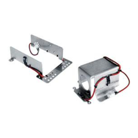
• La résistance pré-câblée (Fig. 1, point 2) doit être introduite entre les deux
dissipateurs avant la fixation pour garantir le contact et donc une diffusion de
chaleur correcte.
• Fixer les dissipateurs termiques du kit de chauffage (1 et 3) aux points prévus
sur le corps du caisson au moyen des vis fournies (4).
• Introduire le connecteur à deux pôles (5) à l'extrémité du câble de la
résistance pré-câblée dans le logement correspondant identifié J3 sur le circuit
de connexion et de câblage (6).
• Positionner le fil du chauffage en utilisant le presse-câble adhésif fourni avec
le kit.
• Repositionner le chariot interne et connecter la tension d'alimentation dans la
borne identifiée J1 sur le circuit de support.
• Fermer le caisson.
FRANCAIS
INSTALLATION:
Der Bausatz ist für den Betrieb mit einer Versorgungsspannung von
115/230VAC oder 12VDC/24VAC.
• Das Gehäuse öffnen und den Innenschlitten herausnehmen.
• Der vorverkabelte Widerstand (Fig. 1, Punkt 2) muß vor der Befestigung zwischen
die zwei Ableiter positioniert werden, um den Kontakt zu garantieren und somit
eine korrekte Wärmediffusion zu ermöglichen.
• Die Wärmeableiter des Heizungskits (1 und 3) an die am Gehäusekörper
vorgesehenen Punkte befestigen, indem man die mitgelieferten Schrauben (4)
verwendet.
• Den 2-Poligen Verbinder (5), der sich am Kabelende des vorverkabelten
Widerstands befindet, in den entsprechenden Verbinder, der am Anschluß und
Verkabelungskreislauf (6) mit J3 bezeichnet wird, einführen.
• Den Heizungsdraht durch den mitgelieferten Klebkabelhalter positioneren.
• Den Innenschlitten wieder einführen und die Betriebsspannung an die im
entsprechenden Kreislauf mit J1 bezeichnete Klemme anschließen.
• Das Gehäuse schließen.
DEUTSCH
INSTALLAZIONE:
Il kit è previsto per il funzionamento con una tensione di alimentazione
pari a 115/230VAC o 12VDC/24VAC.
• Aprire la custodia e rimuovere la slitta interna.
• La resistenza precablata (Fig. 1, punto 2) deve essere interposta tra i due dissipatori
prima del fissaggio per garantire il contatto e assicurare in questo modo una
corretta diffusione del calore.
• Fissare i dissipatori del kit di riscaldamento (1 e 3) nei punti predisposti sul corpo
della custodia utilizzando le viti fornite (4).
• Inserire il connettore a due poli (5) posto all’estremità del cavo della resistenza
precablata, nel suo corrispondente indicato con J3 sul circuito di collegamento e
cablaggio (6).
• Posizionare il filo del riscaldamento utilizzando il ferma-cavo adesivo fornito con il kit.
• Riposizionare la slitta interna e collegare la tensione di alimentazione nel morsetto
indicato con J1 sul circuito d’appoggio.
• Chiudere la custodia.
ITALIANO
INSTALLATION:
The kit is designed to operate with a power supply voltage of
115/230VAC or 12VDC/24VAC.
• Open the housing and remove the internal slide.
• The pre-wired resistance (Fig. 1, point 2) should be placed between the two
dissipators before fixing, to guarantee contact and in this way ensure correct
heat diffusion.
• Fix the heating dissipators of the kit (1 and 3) at the prepared points on the
housing body, using the screws supplied (4).
• Insert the two-pin connector (5), at the end of the pre-wired resistance
cable, in its corresponding socket shown as J3 on the connection and wiring
circuit (6).
• Position the heating wire using the adhesive cable-slide supplied with the kit.
• Reposition the internal slide and connect the power supply to the terminal
shown as J1 on the support circuit.
• Close the housing.
ENGLISH Fig. 1
IN 115/230VACOUT 115/230VAC
12VDC OUT
24VAC OUT
GND OUT
24VAC OUT
GND IN
24VAC IN
+12VDC
24VAC
Fig. 2 Fig. 3

This manual suits for next models

1

Other Videotec Heater manuals

Videotec UPTHT1 User manual

Videotec

Videotec UPTHT1 User manual

Videotec ODBH18K1 User manual

Videotec

Videotec ODBH18K1 User manual

Popular Heater manuals by other brands

Vermont Castings The Intrepid 1695CE Installation and operating manual

Vermont Castings

Vermont Castings The Intrepid 1695CE Installation and operating manual

SHX SHX02HS2000 operating manual

SHX

SHX SHX02HS2000 operating manual

Atlantic Compact 200 L ELECTRIC DIAGRAM

Atlantic

Atlantic Compact 200 L ELECTRIC DIAGRAM

kayami SM 1500 instruction manual

kayami

kayami SM 1500 instruction manual

Atlantic Shangai 2 manual

Atlantic

Atlantic Shangai 2 manual

Draper ESH2000C instructions

Draper

Draper ESH2000C instructions

Goldair Select GSRH150 operating instructions

Goldair

Goldair Select GSRH150 operating instructions

Termozeta TZR08 instruction manual

Termozeta

Termozeta TZR08 instruction manual

DeLonghi TRD0715T Important instructions

DeLonghi

DeLonghi TRD0715T Important instructions

STIEBEL ELTRON ETW 12 Operation and installation

STIEBEL ELTRON

STIEBEL ELTRON ETW 12 Operation and installation

Dimplex RPX Series quick start guide

Dimplex

Dimplex RPX Series quick start guide

Rosthal PTC-2702L instruction manual

Rosthal

Rosthal PTC-2702L instruction manual

Wacker Neuson E1100 Operator's manual

Wacker Neuson

Wacker Neuson E1100 Operator's manual

NOBOCOOL G3 Series installation instructions

NOBOCOOL

NOBOCOOL G3 Series installation instructions

AEG WKL 503 S/U Operation and installation manual

AEG

AEG WKL 503 S/U Operation and installation manual

Factory Buys Direct FBDC80V owner's manual

Factory Buys Direct

Factory Buys Direct FBDC80V owner's manual

Desa RM35E owner's manual

Desa

Desa RM35E owner's manual

Toyotomi LC-44 instruction manual

Toyotomi

Toyotomi LC-44 instruction manual

manuals.online logo
manuals.online logoBrands
  • About & Mission
  • Contact us
  • Privacy Policy
  • Terms and Conditions

Copyright 2025 Manuals.Online. All Rights Reserved.