INSTALLAZIONE:
•Inserire il connettore a 6 poli del cavo dell’alimentatore (Fig. 1) nel corrispondente
connettore sul circuito di appoggio, indicato con J5 (Fig. 2).
•Chiudere la custodia operando in maniera inversa a quanto descritto
precedentemente.
INSTALLATION:
•Insert the 6 poles connector of the power supply cable (1) in the correspondant
connector on the circuit, shown as J5 (Fig. 2).
•Close the housing by proceeding in the reverse order to that described above.
INSTALLATION:
•Insérer le connecteur à 6 pôles du câble de l'alimentation (Fig. 1) dans le
connecteur correspondant sur le circuit de support signalé comme J5 (Fig. 2).
•Fermer le caisson en effectuant les opérations indiquées ci-dessus mais en sens
contraire.
INSTALLATION:
•Den 6-poligen Kabelstecker des Netzteiles (Fig. 1) in die zugehörige, mit J5
bezeichnete Steckbuchse auf der Trägerschaltung einfügen (Fig. 2).
•Nun das Gehäuse in umgekehrter Reihenfolge schließen, wie oben beschrieben.
ITALIANO ENGLISH
FRANCAIS DEUTSCH
Prima di eseguire qualsiasi operazione ricordarsi di togliere tensione al
prodotto.
Per il corretto funzionamento è prevista una tensione d’alimentazione
pari a 230VAC, 50 Hz.
Non alimentare il kit con una tensione diversa da quella indicata!
Before carrying out any operation remember to disconnect the power
supply from the product.
For a correct working use a power supply voltage of 230VAC,
50 Hz.
Never power the kit with a voltage different from the one indicated!
Ne pas oublier de placer le produit hors tension avant de procéder à
toute opération.
Pour un fonctionnement correct, une tension d'alimentation de 230VAC,
50 Hz est prévue.
Ne pas alimenter le kit avec une tension autre que celle indiquée!
Vor Beginn jedweder Tätigkeit ist die Stromversorgung des Produktes
zu unterbrechen.
Für den einwandfreien Betrieb ist eine Versorgungsspannung von
230VAC, 50 Hz vorgesehen.
Das Kit darf nicht mit einer Spannung versorgt werden, die vom
angegebenen Wert abweicht!
ITALIANO ENGLISH
FRANCAIS DEUTSCH
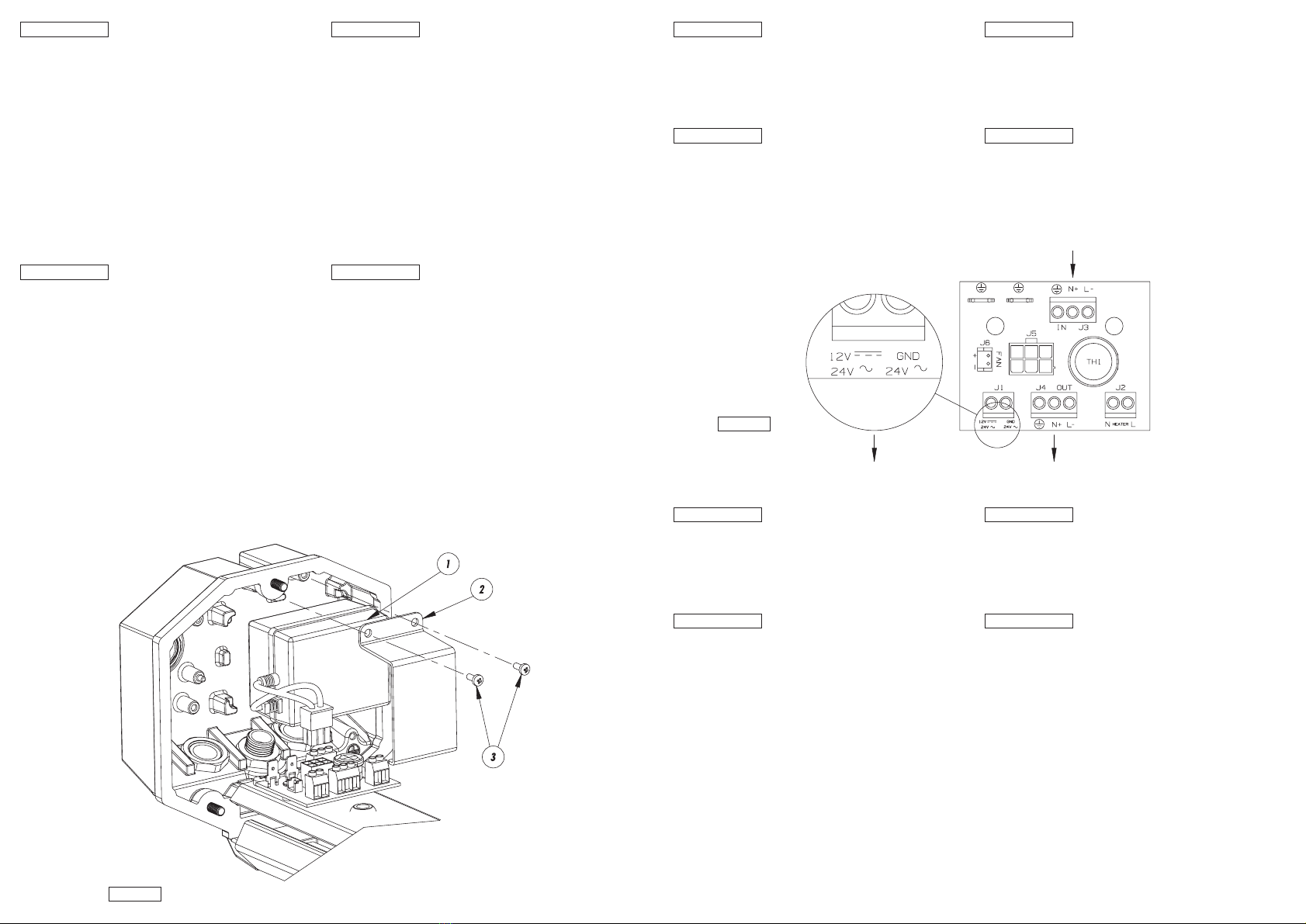
Fig. 2
Fig. 1
COMPOSANTS:
1. Alimentation 230VAC/24VAC, 400 mA
2. Support alimentation
3. Vis de fixation
L’alimentation n’est pas applicable pour les caissons équipés de
système pour le refroidissement installé.
INSTALLATION:
•Ouvrir le caisson en desserrant les 3 vis du fond postérieur.
•Positionner l'alimentation (1) fournie avec le kit dans le logement prévu sur le fond
postérieur du caisson (Fig. 1).
•Fixer l'alimentation au fond du caisson au moyen du support prévu (2) et des vis
(3) fournies avec le kit (Fig. 1).
FRANCAIS
KOMPONENTEN:
1. Netzteil 230VAC/24VAC, 400 mA
2. Halterung für Netzteil
3. Befestigungsschrauben
Das Netzteil ist in den Gehäusen mit installiertem Kühlsystem nicht
anwendbar.
INSTALLATION:
•Das Gehäuse wird geöffnet, indem man die 3 Schrauben der hinteren Abdeckplatte
entfernt.
•Das Netzteil (1) aus dem Lieferumfang des Kits in der vorgesehenen
Aufnahmestelle auf der hinteren Abdeckplatte des Gehäuses positionieren (Fig. 1).
•Das Netzteil mit der zugehörigen Halterung (2) und den beiliegenden Schrauben
(3) an der Abdeckplatte des Gehäuses fixieren (Fig. 1).
DEUTSCH
COMPONENTI:
1. Alimentatore 230VAC/24VAC, 400 mA
2. Supporto alimentatore
3. Viti di fissaggio
L’alimentatore non è applicabile nelle custodie munite di sistema per il
raffreddamento installato.
INSTALLAZIONE:
•Aprire la custodia svitando le 3 viti del fondo posteriore.
•Posizionare l’alimentatore (1) fornito in dotazione al kit nell’apposito
alloggiamento previsto sul fondo posteriore della custodia (Fig. 1).
•Fissare l’alimentatore al fondo della custodia con l’apposito supporto (2) e le viti (3)
fornite in dotazione al kit (Fig. 1).
ITALIANO
PARTS:
1. Power supply 230VAC/24VAC, 400 mA
2. Power supply bracket
3. Fixing screws
The power supply is not applicable to cases with installed cooling
device.
INSTALLATION:
•Open the housing unscrewing the 3 screws on the rear side.
•Place the equipped power supply (1) in the site view for this purpose of the rear
side of the housing (Fig. 1).
•Fix the power supply on the bottom of the housing using the special bracket (2) and
the equipped screws (Fig. 1).
ENGLISH