manuals.online logo
Brands
  1. Home
  2. •
  3. Brands
  4. •
  5. Videotec
  6. •
  7. Receiver
  8. •
  9. Videotec DTWRX User manual

Videotec DTWRX User manual

MNVKDTWRX_0717
Il produttore declina ogni responsabilità per eventuali danni derivanti da un uso improprio delle
apparecchiature menzionate in questo manuale. Si riserva inoltre il diritto di modificarne il contenuto senza
preavviso. Ogni cura é stata posta nella raccolta e nella verifica della documentazione contenuta in questo
manuale, tuttavia il produttore non può assumersi alcuna responsabilità derivante dall’utilizzo della stessa.
Lo stesso dicasi per ogni persona o società coinvolta nella creazione e nella produzione di questo manuale.
The manufacturer declines all responsibility for any damage caused by an improper use of the
appliances mentioned in this manual. Furthermore, the manufacturer reserves the right to modify its
contents without any prior notice. The documentation contained in this manual has been collected with
great care, the manufacturer, however, cannot take any liability for its use. The same thing can be said
for any person or company involved in the creation and production of this manual.
Le producteur décline toute responsabilité pour les dommages éventuels dus à une utilisation non
appropriée des appareils mentionnés dans ce manuel. On réserve en outre le droit d’en modifier le
contenu sans préavis. La documentation contenue dans ce manuel a été rassemblée et vérifiée avec
le plus grand soin, cependant,le producteur ne peut pas s’assumer aucune responsabilité dérivante de
l’emploi de celle-là. La même chose vaut pour chaque personne ou société impliquées dans la création
et la production de ce manuel.
Der Hersteller lehnt jede Haftung für eventuelle Schäden ab, die aufgrund unsachgemäßer Anwendung
der in diesem Handbuch erwähnten Geräte entstanden ist. Ferner behält er sich das Recht vor, den
Inhalt ohne Vorkündigung abzuändern. Die Dokumentation in diesem Handbuch wurde sorgfältig
ausgeführt und überprüft, dennoch kann der Hersteller keine Haftung für die Verwendung übernehmen.
Dasselbe gilt für jede Person oder Gesellschaft, die bei der Schaffung oder Produktion von diesem
Handbuch miteinbezogen ist.
ITALIANO ENGLISH
FRANCAIS DEUTSCH
CONTROLLI WIPER/WASHER:
• Le tastiere DCJ and DCT VIDEOTEC utilizzano i pulsanti WIPER/WASHER: tenendoli
premuti attivano la relativa funzione, rilasciandoli il WIPER/WASHER si ferma.
• La tastiera DCTEL VIDEOTEC (Macro) e i prodotti PELCO D utilizzano i comandi AUX 3
e AUX 4. AUX 3 attiva e disattiva il WIPER mentre AUX 4 attiva e disattiva il WASHER.
SOLUZIONE DEI PROBLEMI:
Qualora si presentassero dei problemi di funzionamento, si consiglia di effettuare
nell’ordine i seguenti controlli:
• Aprire l’alloggiamento del ricevitore prestando particolare attenzione a non venire
in contatto con le parti in tensione.
• Controllare l’accensione del led verde sulla scheda base, qualora fosse spento togliere
alimentazione sezionando il dispositivo e controllare i fusibili sulla scheda washer.
• Controllare la corretta configurazione dei dip switch. Se si dovesse riscontrare una
configurazione errata, togliere alimentazione, configurare correttamente i dip
switch e fornire nuovamente alimentazione al dispositivo.
• Controllare il corretto cablaggio della linea di telemetria. Se i cavi A e B sono
invertiti, il dispositivo non funziona. Controllare la terminazione della linea RS485.
WIPER/WASHER CONTROL:
• DCJ and DCT VIDEOTEC keyboards use WIPER/WASHER buttons: when pressed, they
activate the corresponding function, when released the WIPER/WASHER stops.
• VIDEOTEC DCTEL keyboard (Macro) and PELCO D products use AUX 3 and AUX 4
commands. AUX 3 enables and disables the WIPER and AUX 4 enables and disables
the WASHER.
TROUBLESHOOTING:
If there are problems during operation, we recommend carrying out the following checks
in the order given below:
• Open the receiver housing, taking special care to prevent contact with live parts.
• Make sure the green LED is on, on the base board; if it is off, disconnect the power
supply by isolating the device and check the fuses on the washer board.
• Make sure the DIP switches are configured correctly. If there is a configuration error,
disconnect the power supply, configure the DIP switches correctly and re-connect the
power supply to the device.
• Make sure the telemetry line wiring is correct. If cables A and B are inverted, the
device will not work. Check the termination of the RS485 line.
CONTRÔLES WIPER/WASHER:
• Les pupitres DCJ et DCT VIDEOTEC utilisent les touches WIPER/WASHER: en les
appuyant on active la fonction relative, en les laissant le WIPER/WASHER s’arrête.
• La pupitre DCTEL VIDEOTEC (Macro) et les produits PELCO D utilisent les commandes
AUX 3 et AUX 4. AUX 3 active et disactive le WIPER et AUX 4 active et disactive le
WASHER.
RÉSOLUTION DES PROBLÈMES:
En cas de problèmes de fonctionnement, il est conseillé d’effectuer dans l’ordre les
contrôles suivants:
• Ouvrir le logement du récepteur en ayant soin d’éviter tout contact avec les
parties sous tension.
• Contrôler l’allumage de la DEL verte sur la carte base, si la DEL est éteinte,
couper l’alimentation en sectionnant le dispositif et contrôler les fusibles sur la
carte washer.
• Contrôler la configuration des Dip-switch. En cas de configuration incorrecte,
couper l’alimentation, configurer correctement les Dip-switch et rétablir
l’alimentation du dispositif.
• Contrôler le câblage de la ligne de télémétrie. Si les câbles A et B sont
inversés, le dispositif ne peut fonctionner. Contrôler la terminaison de la ligne
RS485.
KONTROLLE WIPER/WASHER:
• Die DCJ und DCT Videotec Tastaturen benutzen die WIPER/WASHER Tasten: beim Drucken
wird die entsprechende Funktion befähigt; beim Wiederlassen wird die Funktion gestoppt.
• Die DCTEL VIDEOTEC (Macro)-tastatur und die PELCO D- Produkte benutzen die AUX
3 und AUX 4- Befehle. AUX 3 betreibt und deaktiviert die WIPER, während AUX 4
betreibt und deaktiviert die WASHER- Funktion
STÖRUNGSBEHEBUNG:
Bei auftretenden Betriebsstörungen wird empfohlen, die folgenden Kontrollen in der
genannten Reihenfolge vorzunehmen:
• Den Empfängersteckplatz öffnen. Achtung, dass Sie nicht mit spannungsführenden
Teilen in Berührung kommen.
• Prüfen, ob die grüne Led auf der Grundplatine aufleuchtet. Falls sie erloschen ist,
unterbrechen Sie durch Abtrennen der Einrichtung die Stromversorgung und prüfen
Sie die Schmelzsicherungen auf der Karte der Waschanlage.
• Prüfen, ob die Dipschalter richtig konfiguriert sind. Wird eine falsche Konfigurierung
festgestellt, die Stromversorgung unterbrechen, die Dipschalter richtig einstellen und
die Stromversorgung der Einrichtung wieder herstellen.
• Prüfen, ob die Telemetrieleitung richtig verkabelt ist. Sollten die Kabel A und
B vertauscht sein, funktioniert die Einrichtung nicht. Kontrollieren Sie die
Abschlussbeschaltung der Leitung RS485.
ITALIANO ENGLISH
FRANCAIS DEUTSCH
Bedienungsanweisung
Manuel d’instructions
Operating instructions
Manuale istruzioni
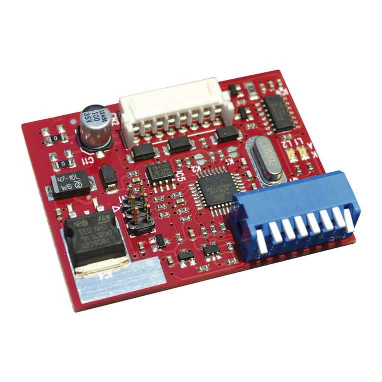
DTWRX: scheda opzione controllo
telemetria tergi/pompa
DTWRX: wisher/pump telemetry
control optional board
DTWRX: carte option contrôle
télémétrie essuie-glace/pompe
DTWRX: Zusatzplatine zur Telemetriesteuerung
der Scheibenwaschanlage mit Pumpenbetrieb
INSTALLAZIONE:
Il ricevitore DTWRX è un accessorio dei sistemi di lavaggio a pompa del
tipo UPTWAS. L’installazione del ricevitore deve essere effettuata da
personale qualificato.
Non alimentare il sistema UPTWAS ad una tensione diversa da quella
specificata nei dati di targa.
Il ricevitore DTWRX include un dispositivo di sicurezza che blocca
il funzionamento della pompa a temperature inferiori ai –10°C per
evitarne il danneggiamento.
• Prima di procedere al montaggio della scheda DTWRX togliere alimentazione al
sistema UPTWAS, sezionando entrambe i conduttori.
• Aprire la scatola del dispositivo UPTWAS.
• Collegare la linea di telemetria sul connettore CN4 in corrispondenza agli ingressi
485/A e 485/B (Fig. 2). Si consiglia di utilizzare un cavo twistato con sezione
minima 0.22mm2(AWG24).
• Se sulla linea RS485 è connesso un solo dispositivo, oppure se questo sia al termine
della linea, è richiesta la chiusura del DIP8 per attivare la terminazione.
• Se previsto collegare il comando per il tergi (soltanto in versione 230V AC) al
connettore CN2, secondo istruzioni del prodotto.
• Inserire la scheda DTWRX nell’apposito alloggiamento (connettore CN5, Fig. 3).
• Configurare i dip switch del ricevitore e richiudere la scatola (Fig. 1).
• Fornire alimentazione al dispositivo, controllare l’esecuzione dei comandi ed
utilizzare normalmente.
INSTALLATION:
The DTWRX receiver is an accessory for wiper systems with
UPTWAS-type pumps. The receiver must be installed by skilled
personnel.
Always power the UPTWAS system at the voltage specified on the data
plate.
The DTWRX receiver has a safety device that stops pump operation at
temperatures below -10°C, to prevent damage.
• Before assembling the DTWRX board, disconnect the power supply to the UPTWAS
system, isolating both conductors.
• Open the box of the UPTWAS device.
• Connect the telemetry line to connector CN4 corresponding to inputs 485/A
and 485/B (Fig. 2). We recommend using twisted cable with minimum section
0.22mm2(AWG24).
• If only one device is on the RS485 line, or if this one terminates the line, you need
to close DIP 8 to enable termination.
• If provided, connect the wiper control (only for the 230V AC version) to the CN2
connector, following the instructions for the product.
• Insert the DTWRX board in the seating provided for this purpose (CN5
connector, Fig. 3).
• Set the receiver DIP switch and close the box properly (Fig. 1).
• Connect the power supply to the device, make sure the controls work correctly and
use as normal.
ITALIANO ENGLISH
INSTALLATION:
Le récepteur DTWRX est un accessoire des systèmes de lavage à pompe
de type UPTWAS. L’installation du récepteur doit exclusivement être
effectuée par un personnel qualifié.
Ne pas alimenter le système UPTWAS à une tension différente de celle
indiquée sur la plaque.
Le récepteur DTWRX comprend un dispositif de sécurité bloquant le
fonctionnement de la pompe en cas de température inférieure à –10°C
pour éviter son endommagement.
• Avant de procéder au montage de la carte DTWRX, couper l’alimentation du système
UPTWAS en sectionnant les deux conducteurs.
• Ouvrir le boîtier étanche du dispositif UPTWAS.
• Connecter la ligne de télémétrie sur le connecteur CN4 à hauteur des entrées 485/A
et 485/B (Fig. 2). Il est conseillé d’utiliser un câble torsadé d’une section min. de
0,22mm2(AWG24).
• En cas de connexion d’un seul dispositif sur la ligne RS485, ou si ce dernier est placé
en extrémité de ligne, la fermeture du DIP8, qui active la terminaison, est nécessaire.
• Si prévu, connecter la commande pour l’essuie-glace (version 230V AC uniquement) au
connecteur CN2 selon les instructions du produit.
• Installer la carte DTWRX dans le logement prévu (connecteur CN5, Fig. 3).
• Configurer les Dip-switch du récepteur et refermer le boîtier (Fig. 1).
• Alimenter le dispositif, contrôler l’exécution des commandes et procéder à l’utilisation
normale.
INSTALLATION:
Der Empfänger DTWRX ist ein Zubehör für mit Pumpe arbeitenden
Waschanlagen des Typs UPTWAS. Der Empfänger muss von Fachleuten
installiert werden.
Das System UPTWAS darf nicht mit einer anderen als der auf den
Kenndatenschildern angegebenen Spannung gespeist werden.
Der Empfänger DTWRX umfasst eine Sicherung, die den Pumpenbetrieb
bei Temperaturen unter –10°C sperrt, um Schäden vorzubeugen.
• Vor dem Einbau der Karte DTWRX muss die Spannungsversorgung des Systems
UPTWAS durch Abtrennen beider Stromleiter unterbrochen werden.
• Den dicht schließenden Kasten der Einrichtung UPTWAS öffnen.
• Die Telemetrieleitung an den Eingängen 485/A und 485/B mit dem Steckanschluss
CN4 verbinden (Fig. 2). Es wird empfohlen, ein verdrilltes Kabel mit einem
Mindestquerschnitt von 0.22mm2(AWG24) zu verwenden.
• Wenn an die Leitung RS485 nur ein Gerät angebunden ist oder dieses sich am
Leitungsende befindet, muss der Schalter DIP8 geschlossen und damit die Leitung
mit Abschlusswiderstand beschaltet werden.
• Falls erforderlich, die Bedienung für die Wischer (nur in der Version 230 V AC)
gemäß den Produktanleitungen an den Stecker CN2 anschließen.
• Die Karte DTWRX in den zugehörigen Steckplatz einfügen (Verbinder CN5, Fig. 3).
• Die Dipschalter des Empfängers einstellen und den Kasten wieder schließen (Fig. 1).
• Das Gerät mit Strom versorgen, die Ausführung der Steuerbefehle testen und die
Einrichtung wie vorgesehen verwenden.
FRANCAIS DEUTSCH
DIP SWITCH
Fig. 1
+/
- /
L
N
ALIMENTAZIONE PRINCIPALE
MAIN SUPPLY
ALIMENTATION PRINCIPALE
HAUPTSTROMVERSORGUNG
FUSIBILE
FUSE
FUSIBLE
SICHERUNG
CONNETTORE DTWRX
DTWRX CONNECTOR
CONNECTEUR DTWRX
DTWRX VERBINDER
COLLEGAMENTO TELEMETRIA RS485
RS485 TELEMETRY CONNECTION
CONNECTION TELEMETRIE RS485
RS485 TELEMETRIE VERBINDUNG
COLLEGAMENTO TERGICRISTALLO 230V AC
230V AC WIPER CONNECTION
CONNECTION ESSUIE-GLACE 230V AC
230V AC WISCHER VERBINDUNG
LEVEL
GND
CMD
GND
ALM
ALM/G
485/A
485/B
GND
Fig. 2
Fig. 3
DIP 8 DIP 7 DIP 6 DIP 5 DIP 4 DIP 3 DIP 2 DIP 1 Impostazioni - Settings - Configurations - Einstellungen
X
Terminazione della linea RS485
Termination of the RS485 line
Terminaison de la ligne RS485
Abschlussbeschaltung der Leitung RS485
OFF linea 485 non terminata / ON linea 485 terminata
OFF line 485 not terminated / ON line 485 terminated
OFF ligne 485 non terminée / ON ligne 485 terminée
OFF Leitung 485 nicht abgeschlossen / ON Leitung 485 abgeschlossen
XProtocollo - Protocol
Protocole - Protokoll OFF Videotec Macro
ON Pelco D
XBaudrate - Baudrate
Vitesse en bauds - Baudrate
MACRO
OFF 9600
ON 38400
PELCO D
OFF 2400
ON 9600
Esempi - Examples - Exemples - Beispiele
OFF OFF OFF OFF OFF RISERVATO - RESERVED - RÉSERVÉ - RESERVIERT
OFF OFF OFF OFF ON INDIRIZZO/ADDRESS/ADRESSE/ADRESSE 01
OFF OFF OFF ON OFF INDIRIZZO/ADDRESS/ADRESSE/ADRESSE 02
OFF OFF OFF ON ON INDIRIZZO/ADDRESS/ADRESSE/ADRESSE 03
... ... ... ... ... ...
ON ON ON ON ON INDIRIZZO/ADDRESS/ADRESSE/ADRESSE 31
CONFIGURAZIONE - CONFIGURATION - CONFIGURATION - KONFIGURATION:
Other manuals for DTWRX

2

Other Videotec Receiver manuals

Videotec RDDT433 User manual

Videotec

Videotec RDDT433 User manual

Videotec DTMRX1 User manual

Videotec

Videotec DTMRX1 User manual

Videotec UEAP User manual

Videotec

Videotec UEAP User manual

Videotec DTWRX User manual

Videotec

Videotec DTWRX User manual

Videotec DTWRX User manual

Videotec

Videotec DTWRX User manual

Videotec MICRODEC485 User manual

Videotec

Videotec MICRODEC485 User manual

Videotec EXDTRX3 User manual

Videotec

Videotec EXDTRX3 User manual

Videotec DTRX3 User manual

Videotec

Videotec DTRX3 User manual

Videotec RDRX2435 User manual

Videotec

Videotec RDRX2435 User manual

Videotec TWM1 User manual

Videotec

Videotec TWM1 User manual

Videotec UEAC User manual

Videotec

Videotec UEAC User manual

Videotec NXPTZSFP User manual

Videotec

Videotec NXPTZSFP User manual

Videotec DTRXDC User manual

Videotec

Videotec DTRXDC User manual

Popular Receiver manuals by other brands

Pioneer SX-770 Installation, operating and service manual

Pioneer

Pioneer SX-770 Installation, operating and service manual

Shure AD4Q user manual

Shure

Shure AD4Q user manual

Onkyo TX-SR501E Service manual

Onkyo

Onkyo TX-SR501E Service manual

Atlas RX-110 Installation and operation manual

Atlas

Atlas RX-110 Installation and operation manual

Massoth DiMAX manual

Massoth

Massoth DiMAX manual

CSI FiberLink 3353 Series user manual

CSI

CSI FiberLink 3353 Series user manual

Niles ZR-4630 ZR-4630 Installation & operation guide

Niles

Niles ZR-4630 ZR-4630 Installation & operation guide

GRAUPNER HoTT GR-18 manual

GRAUPNER

GRAUPNER HoTT GR-18 manual

Dish Network SR200 user guide

Dish Network

Dish Network SR200 user guide

FreeFlight ADS-B FDL-978 Series installation manual

FreeFlight

FreeFlight ADS-B FDL-978 Series installation manual

Aiwa Z-R500 Service manual

Aiwa

Aiwa Z-R500 Service manual

Springtree DMX512 User manual and installation guide

Springtree

Springtree DMX512 User manual and installation guide

Philips D2999 manual

Philips

Philips D2999 manual

Garmin GDL 51 user guide

Garmin

Garmin GDL 51 user guide

Nusky N2 user manual

Nusky

Nusky N2 user manual

FAAC XT 868 SLH LR quick start guide

FAAC

FAAC XT 868 SLH LR quick start guide

Altimium TP70WP user manual

Altimium

Altimium TP70WP user manual

Integra DTR-7.3 Service manual

Integra

Integra DTR-7.3 Service manual

manuals.online logo
manuals.online logoBrands
  • About & Mission
  • Contact us
  • Privacy Policy
  • Terms and Conditions

Copyright 2025 Manuals.Online. All Rights Reserved.