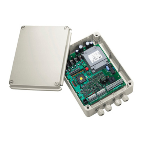
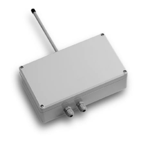
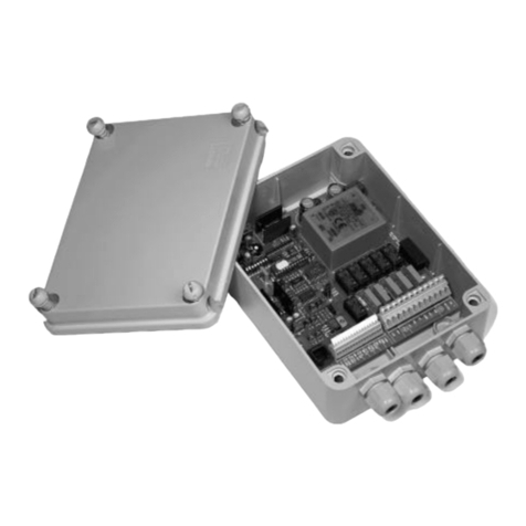
Videotec EXDTRX3 User manual


EN - English - Instructions manual
3
Contents
ENGLISH
1 About this manual........................................................................................................ 5
1.1 Typographical conventions ................................................................................................................................ 5
2 Notes on copyright and information on trademarks ................................................ 5
3 Safety rules ................................................................................................................... 5
4 Identification ................................................................................................................ 6
4.1 Product description and type designation................................................................................................... 6
4.2 Product markings................................................................................................................................................... 7
5 Preparing the product for use..................................................................................... 7
5.1 Contents and unpacking..................................................................................................................................... 7
5.2 Safely disposing of packaging material ......................................................................................................... 8
6 Assembling and installing ........................................................................................... 8
6.1 Installation ................................................................................................................................................................ 8
6.1.1 Receiver opening ................................................................................................................................................................... 8
6.1.2 EXDTRX3 power supply........................................................................................................................................................ 8
6.1.3 EXDTRX324 power supply................................................................................................................................................... 9
6.1.4 Configuration of dip switches and jumpers...............................................................................................................10
6.2 Configuration.........................................................................................................................................................11
6.2.1 Receiver identification number setting .......................................................................................................................11
6.2.2 Receiving mode....................................................................................................................................................................11
6.2.3 Setting of RS485 line load.................................................................................................................................................11
6.2.4 Type of lenses used..............................................................................................................................................................11
6.2.5 Auxiliary contacts.................................................................................................................................................................11
6.2.6 Communication speed protocol setup........................................................................................................................12
6.2.7 AUX3 / AUX4 auxiliary devices setting .........................................................................................................................12
6.2.8 Connection with the control unit...................................................................................................................................12
6.2.9 Connection with the RS485 line .....................................................................................................................................12
6.2.10 Connecting more than one receiver in cascade (point-to-point connection) ............................................13
6.2.11 More than one receiver per line, connection with twisted pair cable (multipoint connection)...........13
6.2.12 Mixed configurations (point-to-point / multi-point) ............................................................................................14
6.2.13 Connection with the Current Loop line.....................................................................................................................15
6.2.14 Connection with the RS232 line...................................................................................................................................15
6.2.15 Adjusting the voltage of the optics controls...........................................................................................................15
6.2.16 Connecting the pan & tilt and optics cables............................................................................................................16
6.2.17 Setting the receiver for PRESET functions ................................................................................................................16
6.2.18 Testing the receiver...........................................................................................................................................................16
6.2.19 Use of the alarm contacts...............................................................................................................................................17
6.2.20 Operation mode of AUX4 ...............................................................................................................................................17
6.2.21 Local keys for P&T motor movement .........................................................................................................................17
6.2.22 PELCO D commands recognised by the receiver...................................................................................................17
6.2.22.1 Example of Patrol sequence programming...................................................................................................................................18
6.2.23 Switching on and switching off....................................................................................................................................18
6.2.24 Dip switch SW6 and SW4 configuration table.........................................................................................................18
7 Maintaining and cleaning.......................................................................................... 19
EN - English - Instructions manual
4
8 Disposal of waste materials....................................................................................... 19
9 Troubleshooting ......................................................................................................... 19
10 Technical specifications ........................................................................................... 20
10.1 General ..................................................................................................................................................................20
10.2 Mechanical ...........................................................................................................................................................20
10.3 Electrical................................................................................................................................................................20
10.4 Communications................................................................................................................................................20
10.5 Protocol .................................................................................................................................................................20
10.6 Accessories...........................................................................................................................................................20
10.7 Environment........................................................................................................................................................20
10.8 Compliance to.....................................................................................................................................................20
10.9 Cable glands ........................................................................................................................................................21
11 Technical drawings................................................................................................... 21
12 Appendix A - CORTEM declaration.......................................................................... 22

EN - English - Instructions manual
5
1 About this manual
Before installing and using this unit, please read this
manual carefully. Be sure to keep it handy for later
reference.
1.1 Typographical conventions
g DANGER!
High level hazard.
Risk of electric shock; disconnect the
power supply before proceeding with any
operation, unless indicated otherwise.
o DANGER!
Explosion hazard.
Read carefully to avoid danger of explosion.
h WARNING!
Medium level hazard.
This operation is very important for the
system to function properly. Please read
the procedure described very carefully and
carry it out as instructed.
j INFO
Description of system specifications.
We recommend reading this part carefully
in order to understand the subsequent
stages.
2 Notes on copyright and
information on trademarks
The quoted names of products or companies are
trademarks or registered trademarks.
3 Safety rules
h The manufacturer declines all responsibility
for any damage caused by an improper use
of the appliances mentioned in this manual.
Furthermore, the manufacturer reserves
the right to modify its contents without any
prior notice. The documentation contained
in this manual has been collected with great
care, the manufacturer, however, cannot
take any liability for its use. The same thing
can be said for any person or company
involved in the creation and production of
this manual.
• Make sure that all the devices are suitable for the
application and for the environment in which they
will be installed.
• Make sure that the connected devices are
completely compatible and suitable for use.
• Make sure the operating temperatures are
compatible with the devices.
• When installing the devices make sure the system
and installer personnel are absolutely safe.
• Make sure that the device is firmly anchored so
that it cannot become detached.
• Since the user is responsible for choosing the
surface to which the device is to be anchored,
we do not supply screws for attaching the device
firmly to the particular surface. The installer is
responsible for choosing screws suitable for the
specific purpose on hand.
• The device must be installed and maintained only
and exclusively by qualified technical personnel.
• Use appropriate tools for the purpose. The
particular nature of the site where the device is to
be installed may mean special tools are required
for installation.
• Make sure that the installation complies with local
regulations and specifications.

EN - English - Instructions manual
6
4 Identification
4.1 Product description and type
designation
Telemetry receiver in an explosion-proof box for
EXPTC and EXPTD explosion-proof Pan & Tilt. It allows
installations in potentially hazardous areas.
EXDTRX3/EXDTRX324 allows the full control of Pan &
Tilt's functions, presets and patrol functions.
The receiver is epoxypolyester powder painted,
RAL7032 colour, IP66.
The explosion-proof box has 4 holes for 3/4" NPT
cable glands.
The cable glands must be selected according to what
is indicated by the EN/IEC 60079-14 Standard.
Available in 230Vac (EXDTRX3) and in 24Vac
(EXDTRX324).
j We recommend using VIDEOTEC cable
glands or equivalent (Tab. 06, page 21).
• This device must be installed out of the reach of
the user or of anyone who might happen to touch
it by chance.
• Before doing any technical work on the device,
disconnect the power supply.
• Do not use power supply cables that seem worn
or old.
• Only qualified technical personnel should be
allowed to open the device, and they should work
in a non-explosive atmosphere. Tampering with
the device will invalidate the guarantee.
• Do not allow children or untrained people to use
the device.
• The device can only be considered to be switched
off when the power supply has been disconnected
and the connection cables to other devices have
been removed.
• Before powering the device install an overload
protection device in the electrical equipment for
the building.
• The user must not install any apparatus inside the
device if it generates dangerous radiation.
• For technical services, consult only and exclusively
authorised technicians.
• Keep this handbook carefully; it must be available
for consultation on the installation site.
• Never, under any circumstances, make any
changes or connections that are not shown in this
handbook: improper use of the device can cause
serious hazards, risking the safety of personnel and
of the system.
• Use only VIDEOTEC original spare parts.
• Before proceeding with installation check the
supplied material to make sure it corresponds
to the order specification by examining the
identification labels ("4.2 Product markings",
page 7).
• Refer and keep with care the CORTEM instruction
manual of the security explosion-proof box.

EN - English - Instructions manual
7
06. GOST-R certification:
• GOST-R certificate number
• Classification of the area type, protection
method and temperature class for which this
product can be used according to the GOST-R
STANDARDS
Label on the electronic card:
• Model identification code;
• IP Grade;
• Voltage (Volt);
• Frequency (Hertz);
• Maximum current (Ampere);
• Product serial number.
h Before installation, make sure the power
supply and protection specifications of the
device correspond to those in the original
order. Use of unsuitable appliances can
cause serious hazards, risking the safety of
personnel and of the installation.
5 Preparing the product
for use
h Any change that is not expressly approved
by the manufacturer will invalidate the
guarantee.
5.1 Contents and unpacking
When the product is delivered, make sure that the
package is intact and that there are no signs that it
has been dropped or scratched.
If there are obvious signs of damage, contact the
supplier immediately.
Keep the packaging in case you need to send the
product for repairs.
Check the contents to make sure they correspond
with the list of materials as below:
• EXDTRX3 / EXDTRX324 receiver
• 2 3/4" NPT IP66 IECEX-ATEX-GOST screws plugs
• Instructions manual
4.2 Product markings
j On the receivers
there are 4 labels.
Labels on the packaging:
• Model identification code;
• Product description;
• IP Grade;
• Voltage (Volt);
• Frequency (Hertz);
• Maximum current (Ampere);
• Product serial number (Extended 3/9 bar code).
Labels on the explosion-proof box:
• Box code (CORTEM);
• Voltage (Volt);
• Frequency (Hertz);
• Power (Watt);
• Maximum current (Ampere);
• Box certificate number (CORTEM);
• Box serial number (CORTEM).
Label on the explosion-proof box:
Serial N°/Сер. №:
Camera/Камера:
WARNING! HEATING RESISTOR POWERED:
DO NOT OPEN WHEN POWERED
ПРЕДУПРЕЖДЕНИЕ! ОТКРЫВАТЬ,
ОТКЛЮЧИВ ОТ СЕТИ (24V/220V)
VIDEOTEC S.p.A.
Via Friuli, 6 - 36015 Schio (VI) - ITALY
www.videotec.com
50/60 Hz
20 Wmax
Model/Модель:
USE STAINLESS STEEL SCREWS, TYPE A2 UNI 5931, DIN 912
01
02
03
04
05
06
EXDTRX324
6 A 40 Wmax
24 V
ГБ05
1ExdeeCT6 и DIP A21 ТАТ85°C
РОСС IT.ГБ05.В02787
Housing/Оболочка:
Fig. 01
01. EX symbol
02. Manufacturer’s name and address
03. Model identification code
04. Serial number
05. Housing
• Power voltage (V)
• Absorbed current (A)
• Frequency (Hz)
• Housing consumption (W)

EN - English - Instructions manual
8
Security screw, to screw/unscrew, for the housing (01)
opening/closing. Body-cover (02) coupling threaded
joint. As required, insert and screw the 3/4" NPT cable
glands and/or the 3/4" NPT blanking caps (03).
01
02
03
Fig. 02
Fig. 03 Internal/external hearth-screws positions.
6.1.2 EXDTRX3 power supply
h The power supply of EXDTRX3 receiver
is 230Vac, 50/60Hz. The receiver must be
earthed using the internal and external
earth screws (Fig. 03, page 8).
Power the receiver via terminal J1 (MAIN INPUT)
located on the support board. Connect the live phase
to terminal L, neutral to terminal N and earth to
terminal a.
5.2 Safely disposing of
packaging material
The packaging material can all be recycled. The
installer technician will be responsible for separating
the material for disposal, and in any case for
compliance with the legislation in force where the
device is to be used.
Bear in mind that if the material has to be returned
due to a fault, using the original packaging for its
transport is strongly recommended.
6 Assembling and
installing
g Disconnect the power supply before
proceeding with any operation, unless
indicated otherwise.
h Only specialised personnel should be
allowed to assemble and install the device.
h Use only cables suitable for the application
and that meet the standards required by
the installation.
h The receiver is not supplied with already
mounted cable glands. Installers must
make sure they choose cable glands that
are in compliance with the EN/IEC 60079-14
standard.
h The unused cable gland holes must be
closed using NPT 3/4" plugs that are
suitable for the housing marking.
6.1 Installation
6.1.1 Receiver opening
For a correct receiver opening and closing, refer to
the following drawings.
o The receiver opening and closing must be
carry out in a non-explosive atmosphere.

EN - English - Instructions manual
9
6.1.3 EXDTRX324 power supply
h The power supply of EXDTRX324 receiver
is 24Vac, 50/60Hz. The receiver must be
earthed using the internal and external
earth screws (Fig. 03, page 8).
Fig. 05
To power the camera use terminal J5, in the part
corresponding to CAMERA OUT (24Vac).
To power the housing heater use terminal J5, in the
part corresponding to HEATER OUT.
J1 - IN 230Vac
J5 - HEATER
OUT 24Vac
J5 - CAMERA
OUT 24Vac
Fig. 04

EN - English - Instructions manual
10
6.1.4 Configuration of dip switches and jumpers
In the following picture identify the dip switches and the configuration jumpers.
IN 24Vac
Ground
Fig. 06
h Be sure the connector is earthed.

EN - English - Instructions manual
11
6.2.2 Receiving mode
According to the communication type to set follow
the following settings:
• Current Loop: JP2 and JP3 to CL position
• RS485: See below "6.2.3 Setting of RS485 line load",
page 11
• RS232: No setting needed
6.2.3 Setting of RS485 line load
• Jumpers: JP5 and JP6
• JP5 in A position: Load connected in RS485 mode
• JP5 in B position: Load disconnected in RS485
mode
• JP6 in A position: Load connected in RS485 mode
• JP6 in B position: Load disconnected in RS485
mode
6.2.4 Type of lenses used
g An inaccurate setup of this parameters can
cause damages to the lenses!
The EXDTRX3 / EXDTRX324receiver can control both
polarity inversion lenses and common wire lenses. In
case of common wire lenses connect the common
wire to FOCUS-.
6.2.5 Auxiliary contacts
The receiver has 4 auxiliary contacts:
• AUX1: 12Vdc, 350mA
• AUX2: 24Vac, 180mA
The following are clean contacts:
• AUX3: 24Vac, 1A
• AUX4: 24Vac, 1A
6.2 Configuration
j The receiver configuration phase allows
to optimize its functioning according to
the particular requirements of the plant.
The unit must be configured exclusively
during the installation phase and by an
installer. We recommend proceeding
with the configuration of the parameters
in a systematic way in order to avoid
installation troubles.
The settings that must be configured the setup phase
are the following:
• Identification number of the receiver;
• Receiving mode setup;
• Type of lenses used;
• Communication speed and protocol;
• AUX3 / AUX4 auxiliary devices;
• Connection with the control unit;
• Control voltage of lenses;
• Connection of the positioning device and the
lenses cables;
• Alarms setting;
• Test of the receiver active functions (for PRESET
operations).
6.2.1 Receiver identification number
setting
Configure the SW1, SW2 and SW3 rotative switches
according to the address to assign to the receiver as
follows:
• SW1: Hundred
• SW2: Ten
• SW3: Unit
Examples:
• Receiver address n. 359:
Set SW1 to 3, SW2 to 5 and SW3 to 9
• Receiver address n. 27:
Set SW1 to 0, SW2 to 2 and SW3 to 7
• Receiver address n. 4:
Set SW1 to 0, SW2 to 0 and SW3 to 4

EN - English - Instructions manual
12
6.2.8 Connection with the control unit
The RJ11 connector (J1 in the Fig. 06, page 10)
supplied to the circuit enables the reception and
the transmission of digital data in RS232 or RS485
allowing a rapid connection of several units in case
of test runs or for the connection of conversion
interfaces available on the market (RS232-optical
fiber, etc.).
The final connection must be in RS485 mode with
DCJ, DCT and DCTEL keyboards. This mode allows to
reach a maximum distance of 1200m.
It is also possible to use control keyboards in Current
loop communication mode.
6.2.9 Connection with the RS485 line
The keyboards (DCJ, DCT and DCTEL) and the receiver
can be directly connected using the telephone
cable supplied by the manufacturer, using the RJ11
(J1 in the Fig. 06, page 10) connector present in
the circuit, as illustrated in the reference diagram
hereunder.
J1DCT
White
Yellow Black
Blue
Fig. 07 Communication mode RS485, max distance 1200m.
j The receiver has the load inserted in
reception and is connected to line A or B on
the keyboard with the load inserted.
On the receiver side it is also possible to make a
simpler connection to terminals RX-485A and RX-
485B as in the following scheme.
TX-B
TX-A
RX-B
RX-A
RS485
TX 485A (White)
TX 485B (Yellow)
To RJ11
keyboard
connector
Receiver
clamps
Fig. 08
6.2.6 Communication speed protocol
setup
h An inaccurate protocol or communication
speed selection can cause damages to the
receiver!
Used in digital transmission systems the EXDTRX3 /
EXDTRX324 receiver can communicate with a speed
varying from 300 to 38400 baud, depending on the
selected protocol.
• Dip switch: Switches 1, 2 and 8 of SW4 e 1 of SW6
PROTOCOL
BAUD RATE SW6 SW4
Dip 1 Dip 1 Dip 2 Dip 8
VIDEOTEC - 300 baud OFF ON OFF ON
VIDEOTEC - 1200 baud OFF OFF ON ON
VIDEOTEC - 9600 baud* OFF OFF OFF ON
VIDEOTEC - 19200 baud OFF ON ON ON
MACRO - 1200 baud OFF OFF ON OFF
MACRO - 9600 baud OFF OFF OFF OFF
MACRO - 19200 baud OFF ON ON OFF
MACRO - 38400 baud OFF ON OFF OFF
PELCO D - 2400 baud ON OFF OFF **
PELCO D - 4800 baud ON ON OFF **
PELCO D - 9600 baud ON OFF ON **
PELCO D - 19200 baud ON ON ON **
Tab. 01 * Default setup.
** Switch setting is indifferent; ON or OFF.
6.2.7 AUX3 / AUX4 auxiliary devices
setting
It is possible to set the functioning of the AUX3 /AUX4
auxiliary devices by setting dip 6 of switch SW4:
• Dip 6 of SW4 set to the OFF (default) position:
The operator has to press the control key in order
to activate the auxiliary device and then to press it
again in order to deactivate it.
• Dip 6 of SW4 set to the ON position: The auxiliary
device remain activated as long as the operator
keeps pressing the relevant control key.
j AUX4 can be activated also on alarm
contact ("6.2.20 Operation mode of AUX4",
page 17).

EN - English - Instructions manual
13
Terminals RX-485A and RX-485B which have the load
inserted, should be connected to terminals TX-485A
and TX-485B respectively of the preceding unit,
which also have the load inserted:
RS485
TX-B
TX-A
RX-B
RX-A
RS485
TX-B
TX-A
RX-B
RX-A
RS485
TX-B
TX-A
RX-B
RX-A
From previous
receiver To next
receiver
Fig. 10
j For the connection in question (point-
to-point) faulty operation of one of the
receivers will switch off all the devices in
cascade.
6.2.11 More than one receiver per line,
connection with twisted pair cable
(multipoint connection)
All receivers connected to the same line should use
the same communication protocol RS485.
For each of the lines the following remarks are valid:
• Only one of the keyboards (that at one end of the
line) has the load inserted;
• Only one of the receivers (at the other end of the
line) has the load inserted;
• The total length of the line should not exceed
1200m.
6.2.10 Connecting more thanone receiver
in cascade (point-to-point connection)
The receivers are able to regenerate the received
signal internally and retransmit it along a new
communication line to the subsequent receiver. Each
of the three sections of line (L1, L2, L3) is considered
independent, and connects only two devices
point-to-point, each with inserted load, over a
maximum distance of 1200m. The distance between
the keyboard and receiver D can therefore be up
to 3600m (1200m between keyboard and receiver
B, 1200m between receiver B and receiver C, and a
further 1200m between receiver C and receiver D, for
a total of 3600m).
C DB
A
EXPT EXPT
DCT
L2
L1
EXPT
EXDTRX3
EXDTRX324 EXDTRX3
EXDTRX324
EXDTRX3
EXDTRX324
L3
Fig. 09
The connection between the keyboard and the first
receiver must be carried out as illustrated in the
diagram in Fig. 08, page 12.

EN - English - Instructions manual
14
6.2.12 Mixed configurations (point-to-
point / multi-point)
This is a combination of the two previous connection
modes and, depending on the combination chosen,
allows the user to exploit the advantages of the
two types of connection to the utmost, significantly
reducing the probability of faulty operation.
The following is an example of mixed connection:
R2R1
K2
EXPTEXPT
EXDTRX3
EXDTRX324
EXDTRX3
EXDTRX324
R3 R4
EXPT EXPT
EXDTRX3
EXDTRX324 EXDTRX3
EXDTRX324
L4L3L2
L1
L1
K1
DCTDCT
Fig. 13
In the example shown, if receiver R3 jams (multi-
point connection in line L3) it will not cause faulty
operation in receiver R4.
R3 is not at the ends of line L3and
it is not therefore necessary to terminate it.
If receiver R2 jams, since it is the "generator" of line
L3, all receivers connected to it in cascade (R3 and R4)
will not receive the commands.
RS485
TX-B
TX-A
RX-B
RX-A
RS485
TX-B
TX-A
RX-B
RX-A
RS485
TX-B
TX-A
RX-B
RX-A
From previous
receiver To next
receiver
Fig. 14
A2 A3A1
EXPT EXPTEXPT
EXDTRX3
EXDTRX324 EXDTRX3
EXDTRX324
EXDTRX3
EXDTRX324
A
DCT
Fig. 11
Line A on keyboard has been used for
communication with telemetry. The ends (Keyboard
- Receiver A3) should have the termination resistor
inserted. Receivers A1, A2 should not have the
termination resistor inserted. The maximum line
length, from end to end (from the keyboard to
receiver A3), is 1200 meters.
RS485
TX-B
TX-A
RX-B
RX-A
RS485
TX-B
TX-A
RX-B
RX-A
RS485
TX-B
TX-A
RX-B
RX-A
From previous
receiver To next
receiver
Fig. 12
j For the connection (multi-point) faulty
operation of one of the receivers will not
influence the other receivers.

EN - English - Instructions manual
15
6.2.14 Connection with the RS232 line
GND
RX
RS232
Al connettore
RJ11 della
tastiera
TX RS232 (Nero)
GND RS232 (Verde)
Morsetti sul
ricevitore
Fig. 17 Communication mode RS232, max distance 15m.
6.2.15 Adjusting the voltage of the
optics controls
• Connect the power supply cable and power the
unit (LD1 lit up);
• Insert a load between terminals FOCUS NEAR and
FOCUS FAR to absorb at least 10 mA (use a resistor
from 100 to 1000 ohm);
• Position the tester prods on terminals FOCUS NEAR
and FOCUS FAR;
• Keep one of the two FOCUS keys on the control
unit pressed down;
• Adjust the control voltage of the optics by
adjusting trimmer TR1 ( default 12Vdc).
h Don’t make unloaded voltage regulation
(without inserting the load) otherwise the
adjustment will be incorrect.
6.2.13 Connection with the Current
Loop line
The various devices can be connected directly using
the telephone cable supplied by the manufacturer.
For normal connections in the field, refer to the
connections made using the shunt boxes RJ, supplied
by the manufacturer, following the reference tables
given below:
KEYBOARD EXDTRX3, EXDTRX324
TX CL Yellow Terminal RX CL
GND CL Red Terminal AGND
Tab. 02 Current Loop Communication Mode, max. distance
1500 meters from receiver, Jumper JP2 and JP3 in
position CL.
From the receiver side the connection should be
made to terminals RXCL and AGND according to the
following scheme:
AGND
TX
AGND
RX
CURRENT LOOP
To RJ11
keyboard
connector
TX CL (Yellow)
GND CL (Red)
Receiver
clamps
Fig. 15
• If the receiver is connected in cascade to another
EXDTRX3 / EXDTRX324 unit, the reception mode
should be set in Current Loop with jumpers JP2
and JP3 in position CL.
• Terminals RX CL and AGND should be connected
to the preceding unit terminals TX CL and AGND
respectively as in the following scheme:
Current
Loop
AGND
TX
AGND
RX
Current
Loop
AGND
TX
AGND
RX
Current
Loop
AGND
TX
AGND
RX
From previous
receiver To next
receiver
Fig. 16

EN - English - Instructions manual
16
6.2.18 Testing the receiver
After having connected the positioning device and
the lens cables, to check the correct working of the
devices, it’s possible to perform an automatic test
which will show the allowed functions:
h Since during this phase the positioning
devices makes automatically some
predetermined movements. Do not lean
on during the test and do not obstruct its
trajectory.
Proceed according to the following indications:
• Power the receiver on;
• Identify the Up arrow-switch (P4 switch) and the
reset switch (P1 switch);
• Keep pushing the Up switch and press the reset
switch;
• Release the reset switch (keep pushing the Up
switch): the automatic test starts;
• After the starting of the test, release the Up switch.
The receiver starts up one function at a time, for
about 3 seconds:
• Pan: Left-right (Led P)
• Tilt: Low-high (Led T)
• Zoom: Wide-tele (Led Z)
• Focus: Far-near (Led F)
• Iris: Close-open (Led I)
The result of the test is shown from the 5 control leds
P, T, Z, F, I (placed near the arrow-switches, Fig. 06,
page 10) at the end of the of the movement of the
Pan&Tilt and lens:
• Led switched on and fixed: The relevant function
(PAN= P, TILT= T, ZOOM= Z, FOCUS= F, IRIS= I)
works correctly;
• Led switched on and blinking: The relevant
function doesn’t work or is not present and cannot
be used for preset/scan/patrol functions.
After some seconds from the end of the test the
receiver automatically starts working.
h A blinking of at least one of the leds at the
end of the test (provided that this function
is included) indicates a malfunction to
which you must find a remedy before the
receiver starts working.
6.2.16 Connecting the pan & tilt and
optics cables
g Before carrying out the following
operations make sure that the pan & tilt
control voltage and the setting for optics
type are correct.
• Disconnect the power supply to the unit;
• Make the connections with the optics and pan &
tilt;
• Reconnect the power supply to the unit.
h For optics and pan & tilt with PRESET
functions (PAN, TILT, ZOOM, FOCUS and
IRIS, VCC and GND), the maximum length
of the preset cables should not exceed 5
metres, otherwise positioning on the stored
positions will be incorrect.
6.2.17 Setting the receiver for PRESET
functions
The receiver has integrated preset functions (for
pan&tilt and the optics).
With PELCO D and MACRO protocols, it is possible to
store up to 40 positions, which can be recalled using
the Scan and Patrol functions on the keyboard.
The receiver is able to make a test to automatically
detect which preset functions are present and
configuring the device is therefore a simple
operation. However, it is necessary to take certain
precautions:
• Before making the receiver test (to determine
which preset functions are active), make sure
the cables for pan&tilt and the optics have been
connected correctly;
• For the preset cables (PAN, TILT, ZOOM, FOCUS,
IRIS, VCC and GND) use cables with a maximum
length of 5m.

EN - English - Instructions manual
17
6.2.22 PELCO D commands recognised
by the receiver
As well as recognising standard PELCO D commands
relating to joystick and lens movements, the receiver
is able to recognise and execute the following
extended PELCO D commands.
PELCO D
COMMAND
EXDTRX3 /
EXDTRX324
COMMAND
NOTE
Set Auxiliary Aux ON Recognise values
between 1 and 4
Clear Auxiliary Aux OFF Recognise values
between 1 and 4
Set Pattern Start Autopan Toggle --
Run Pattern Patrol Toggle --
Remote Reset Receiver Reset --
Go To Preset
“1÷40”
Scan Recognise values
between 1 and 40
Set Preset“1÷40” Preset position Recognise values
between 1 and 40
Clear Preset
“1÷40”
Reset of Preset
Single Position
Recognise values
between 1 and 40
Set Preset“41” Starting Patrol
parameters
acquisition
(see example**)
--
Set Preset“…” Patrol “Position
From”
Recognise values
between 1 and 40
Set Preset“…” Patrol “ Position
To”
Recognise values
between 1 and 40
Set Preset“…” Patrol “Pause” Recognise values
between 1 and 99
Set Preset“42” Patrol Start --
Set Preset“43” Patrol Stop --
Set Preset“44” Washer-Wiper* --
Set Preset“55”
Set Preset“66”
Reset of all Preset
positions
The two
commands
must be given in
sequence
Tab. 03 * With the following timing: in the first second, only
the Washer is activated, in the next two seconds the
Washer and Wiper are activated simultaneously, and
then during the last second the Washer is switched off
and just the Wiper is left on.
6.2.19 Use of the alarm contacts
The 4 alarm contacts of EXDTRX3 / EXDTRX324
receiver are associated with the first four preset
positions; as soon as the alarm is activated,
the positioning device and the lens adopt the
corresponding preset position; the last alarm
activated takes always priority. The EXDTRX3 /
EXDTRX324 can also receive an alarm command
even through theDCJ, DCT and DCTEL control
keyboard (which in turn receives it from the SM164B
and SM328B matrix); in such case the positioning
device and the lens move themselves into the preset
position n°1.
In order to use the alarm contacts it is necessary to
set the SW4 according to the following instructions:
• Dip 3 of SW4 set to the ON position: The alarm
contacts are activated;
• Dip 3 of SW4 set to the OFF position: The alarm
contacts are deactivated;
• Dip 4 of SW4 set to the ON position: The alarm
contacts are normally open;
• Dip 3 of SW4 set to the OFF position: The alarm
contacts are normally closed.
6.2.20 Operation mode of AUX4
• Switches: Dip 5 of SW4
Settings:
• Dip 5 of SW4 OFF: Normal operation;
• Dip 5 of SW4 ON: AUX4 is activated on alarm and
deactivated when the alarm signal stops.
6.2.21 Local keys for P&T motor
movement
The receiver has 4 local arrow-keys (on board) for
the P&T motor movement in the 4 directions (Up,
Down, Left, Right, Fig. 06, page 10). These keys are
very useful during P&T motor installation in order
to control the position of limit switches and/or the
right setting of the P&T motor. The arrow-keys have
total priority and, when pressed, they deactivate at
the moment the receiver remote use (by keyboards).
When the arrow-keys are released the receiver
functions are fully restored.
The combination of Up key and reset key is used to
carry out the auto-test ("6.2.18 Testing the receiver",
page 16).

EN - English - Instructions manual
18
6.2.24 Dip switch SW6 and SW4
configuration table
SW6
Dip Position Function
1 ON PELCO D protocol
1 OFF VIDEOTEC or MACRO
protocols (setting the dip 8
of SW4)
2, 3, 4 Indifferent No function
SW4
Dip Position Function
1, 2 OFF, OFF 9600 baud* (VIDEOTEC and
MACRO), 2400 PELCO D
1, 2 ON, OFF 300 baud VIDEOTEC, 38400
baud MACRO, 4800 baud
PELCO D
1, 2 OFF, ON 1200 baud (VIDEOTEC and
MACRO), 9600 baud PELCO D
1, 2 ON, ON 19200 baud (VIDEOTEC,
MACRO and PELCO D)
3 OFF Unused alarms*
3 ON Used alarms
4 OFF N.C. alarms*
4 ON N.O. alarms
5 OFF -
5 ON Alarms on Aux4
6 OFF -
6 ON To release Aux3 and Aux4
7 OFF -
8 ON** VIDEOTEC standard
protocol****
8 OFF*** MACRO protocol **** ((DCIR,
DCJ, DCT and DCTEL)
Tab. 04 * Default settings.
** Compatible with keyboards DCIR, DCJ, DCT and
DCTEL with VIDEOTEC standard protocol.
*** Compatible with keyboards DCIR, DCJ, DCT and
DCTEL with MACRO protocol.
**** Selectable only if the dip 1 of SW6 is in OFF
position.
6.2.22.1 Example of Patrol sequence
programming.
If you want to set up a Patrol sequence that starts
from Preset position 19, ends at Preset position 33
and stops for one minute at every position reached:
: Enables parameter insertion;
: Start Patrol at position 19;
: End Patrol at position 33;
: Pause of 60 seconds at every position
reached;
: Start of sequence;
: End of sequence.
6.2.23 Switching on and switching off
Before connecting the unit:
• Make sure that the goods supplied correspond
to the required specifications by controlling the
rating plates ("4.2 Product markings", page 7);
• Make sure that the fuses of the EXDTRX3 /
EXDTRX324 receiver are not damaged;
• Make sure that the receiver and the other
components of the plant are closed in order to
avoid the direct contact with live elements;
• Make sure that all parts are accurately and firmly
fixed;
• The power cords must not hamper the normal
operations of the installer and the movement of
the positioning device;
• Make sure that all power sources and the
connecting cables are able to bear the system
consumption.
This manual suits for next models
1
Table of contents
Languages:
Other Videotec Receiver manuals

Videotec
Videotec DTRXDC User manual

Videotec
Videotec DTWRX User manual

Videotec
Videotec MICRODEC485 User manual

Videotec
Videotec RDRX2435 User manual

Videotec
Videotec NXPTZSFP User manual

Videotec
Videotec DTWRX User manual

Videotec
Videotec DTRX3 User manual

Videotec
Videotec DTMRX1 User manual

Videotec
Videotec RDDT433 User manual

Videotec
Videotec UEAP User manual