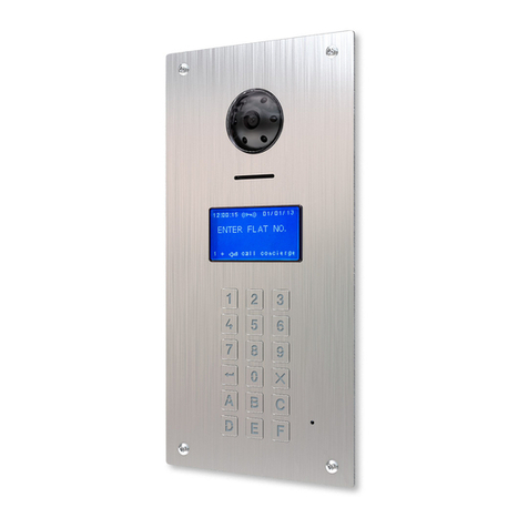
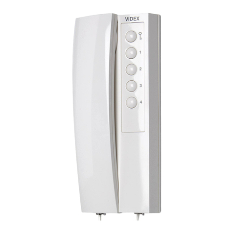
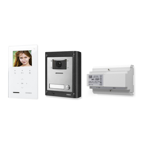
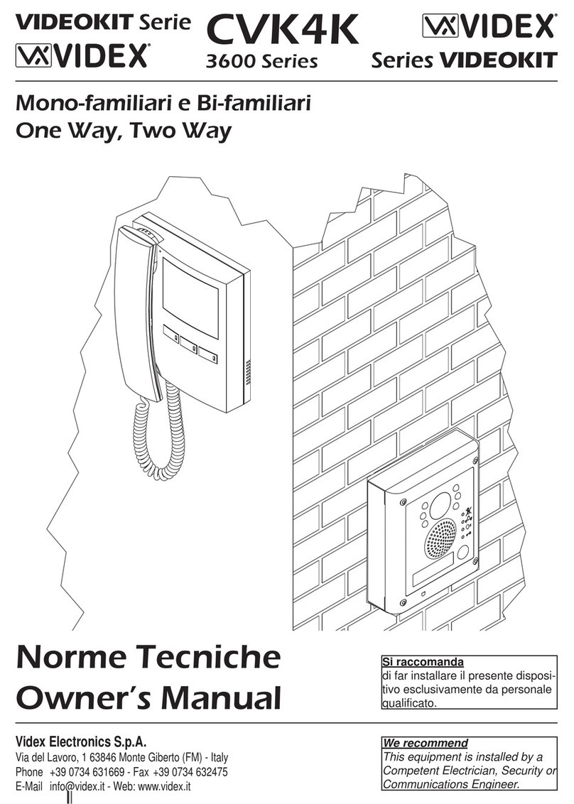
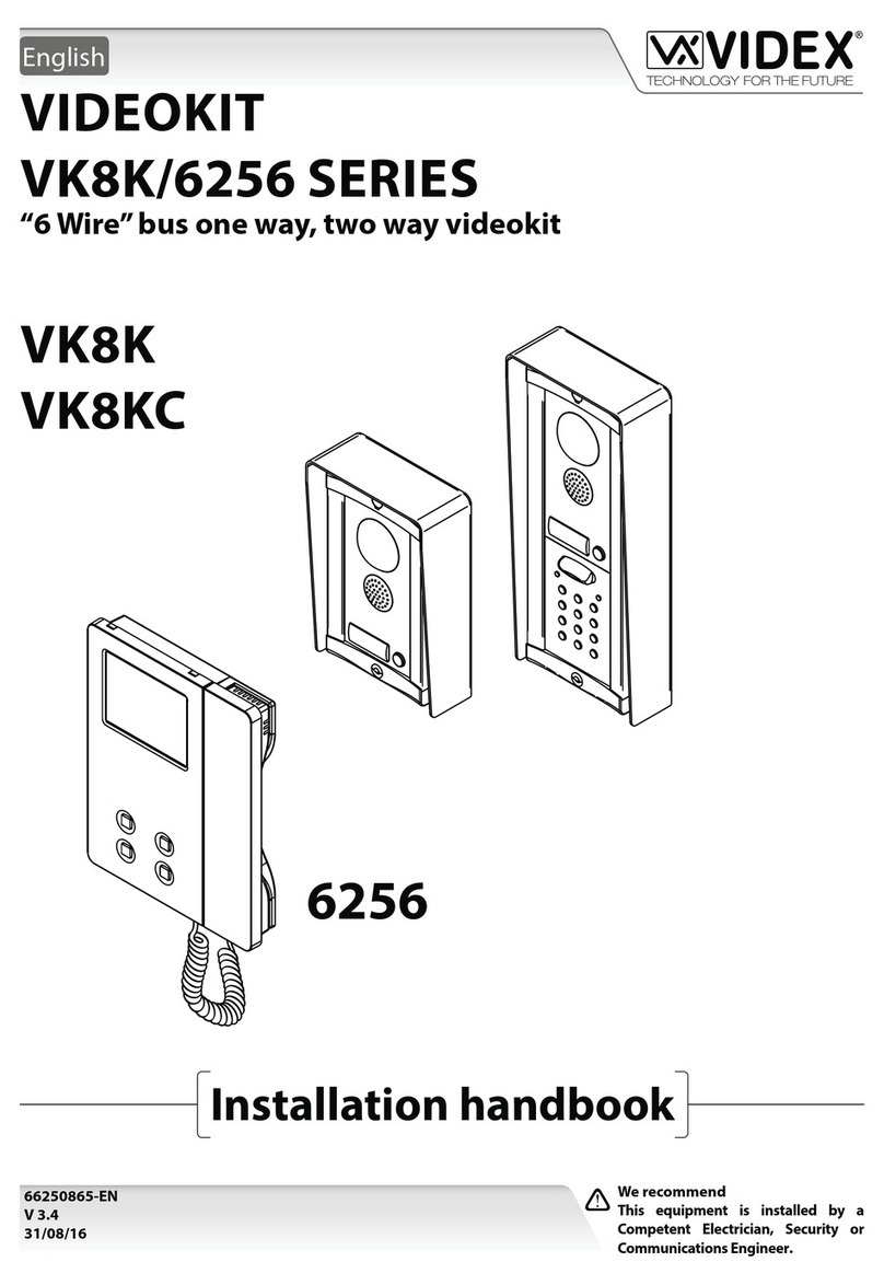
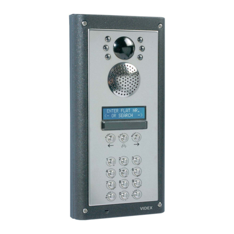
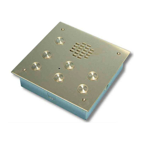
Videx VR120 VANDAL User manual

VR120 VANDAL RESISTANT AUDIO
AND VIDEO DOOR ENTRY SYSTEMS
(136 AMPLIFIER)
TECHNICAL MANUAL EDITION 1.0

120 VANDAL RESISTANT AUDIO AND VIDEO TECHNICAL MANUAL VER 1.0Page 2

CONTENTS
PAGE
Manual Introducon 4
System Introducon 4
System Components 5
Door Panels 5 - 7
Addional Panel Components 7 - 9
VR120 Panel Dimensions 9
VR120 Back Box Dimensions 10 - 11
Power Supplies & Control Equipment 12 - 15
Audiophones 16
• 3000 Series Audiophones 16
• 5000 Series Apartment Staons 17 - 19
Videophones 19
• 3600 Series Videophones 19 - 25
• 5000 Series Handsfree Eclipse 25 - 28
Accessories 29
Deskmount Kits 30 - 32
Installaon 32
Cable Type and Cable Size Guide 33 - 36
Block Diagrams 36
• Audio System Block Diagram 36
• Video System Block Diagram 37
Panel & Back Box Installaon 38
Panel Care 39
Tesng the Installaon 40
Accessories Connecon Guide 41 - 42
Codelock Programming Guide 43 - 44
Timeclock Programming Guide 45
Wiring Diagrams 46
• Audio System Wiring Diagram 46
• Video System Wiring Diagram 47
Trouble Shoong 48 - 49
Notes 50 - 51
Page 3120 VANDAL RESISTANT AUDIO AND VIDEO TECHNICAL MANUAL VER 1.0

MANUAL INTRODUCTION
The informaon in this manual is intended as an installaon and commissioning guide for the Videx
VR120 range of vandal resistant door panels, to be used with standard electronic call tone telephones
or videophones using the Art.520M and Art.893N power supplies. This manual should be read carefully
before the installaon commences. Any damage caused to the equipment due to faulty installaons
where the informaon in this manual has not been followed is not the responsibility of Videx Security
Ltd.
VIDEX run free training courses for engineers who have not installed this system
before. Technical help is also available on 0191 224 3174 during oce hours or via
e-mail tech@videx-security.com.
An electronic copy of this technical manual can be downloaded by scanning the QR
code to the right.
SYSTEM INTRODUCTION
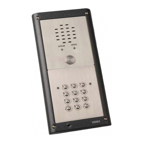
The VR120 door panels are all 120mm wide and have CALL PROGRESS LEDs for ‘SPEAK’, ‘DOOR OPEN’
and ‘BUSY’ along with disnct audio reassurance tones to assist the visitor. The panels come with
buons that are IP68 rated with the opon of a yellow bezel oering a high contrast to the facia for DDA
requirements. All face plates are deep engraved with 6mm in-lled black characters to idenfy each
buon. Oponal colours for specic applicaons can be specied along with custom logos. The VR120
face plates are aached to their back box with either 4 or 6 an-vandal xings depending on panel size
and opons. All face plates are ed with a purpose manufactured neoprene seal to prevent the ingress
of dust and liquid.
All audio ampliers and microphones are protected with a ne oset stainless steel mesh to protect
against vandalism. All speakers have Mylar cones to further protect against the eects of moisture.
Full control of volume levels to the amplier and the telephones can be adjusted independently on the
136 amplier with two POT controls, one for the speaker and one for the microphone. Also addional
features including speech me, lock release me and reassurance volume can be adjusted by the
posioning of a series of dip-switches and jumpers.
Flush back boxes are standard. Stainless steel bezel ush boxes and surface
with rain shield are also available across the range (see pages 10 and 11).
Key Features
• 12 Gauge stainless steel.
• IP68 rated buons with oponal yellow bezel.
• SPEAK, BUSY and OPEN call progress LEDs.
• Call progress reassurance tones.
• Dry contact relay output for lock release or gate controller.
• Timed call, speech and lock release.
• Speaker and microphone volume adjustment.
These panels can be used for single entrance or mulple entrance systems.
We would suggest using this system on small to medium sized installaons of
no more than 20 apartments.
120 VANDAL RESISTANT AUDIO AND VIDEO TECHNICAL MANUAL VER 1.0Page 4

SYSTEM COMPONENTS
A
standard audio system will comprise of a door panel, power supply and audio telephones. A standard
video system will comprise of a door panel, audio and video power supplies, video spliers and
videophones. The individual parts are described below.
DOOR PANELS
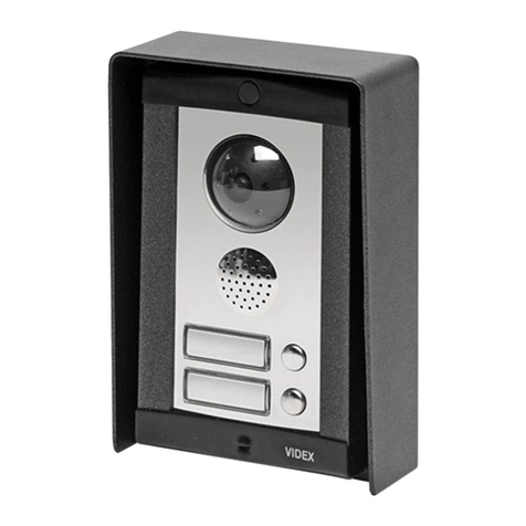
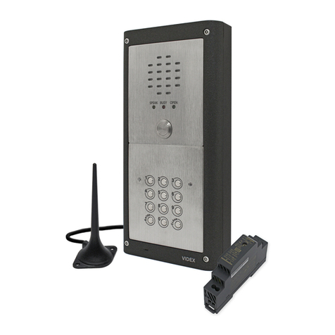
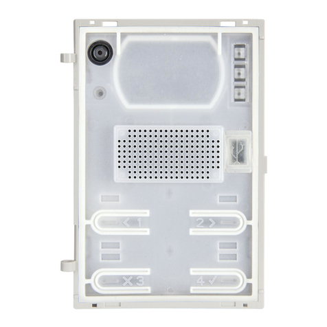
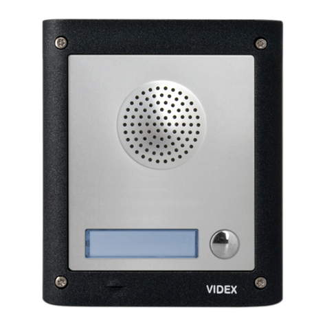
An audio or video vandal resistant door panel will consist
of a 136 amplier module, buon connector board and
‘n’ number of buons. Addionally call buons can be
engraved to suite the apartment numbers.
Speaker module connecons, switches and jumper
Dip-Switches
The four way dip-switch bank has the following funcons.
Please note: dip-switches must be set before power up. Any
changes made when power is on will not take eect unl a
power down reset.
Speech Time
Switch 1 OFF 1 minute
Switch 1 ON 2 mintues
Relay Time
Switch 2 OFF
Switch 3 OFF 2 seconds Switch 2 ON
Switch 3 OFF 8 seconds
Switch 2 OFF
Switch 3 ON 4 seconds Switch 2 ON
Switch 3 ON 20 seconds
Speech Live
Switch 4 OFF Only when called
Switch 4 ON (only possible on
one door systems)
Speech live whenever
handset lied
Jumper
Jumper JP controls the reassurance tone volume level at the door panel.
adjustment for speech volume
at the apartment (microphone)
adjustment for speech volume level
at the door staon (speaker)
POTS
Speech volume adjustments are carried out at the door panel using a small trimmer driver.
Posion H High volume reassurance tone
Posion L Low volume reassurance tone
No Jumper No reassurance tone
Page 5120 VANDAL RESISTANT AUDIO AND VIDEO TECHNICAL MANUAL VER 1.0

VX136 Amplier Module VX136 Current Rang on +12Vdc
Connecon Funcon Condion Current (mA)
1 Receive speech from apartment Standby 18mA
2 Transmit speech to apartment System busy 58mA
+ +12Vdc input During a call 122mA
- 0V (Ground) Live speech 108mA
5 Switched 0V from phone to trigger door release relay Lock Release 125mA
TElectronic call tone output to common side of call buons Maximum 130mA
- 0V for use with push to exit input (PTE)
PTE Switched 0V input from push to exit buon to trigger door release relay
CCommon connecon of dry contact relay
NC Normally closed connecon of dry contact relay
NO Normally open connecon of dry contact relay
D+ External link to door open (+12V side) LED. Not used with this kit
D- External link to door open (0V side) LED. Not used with this kit
BSY Busy signal for use with mulple door systems (Normally high, 12V. Low when busy 0V)
SL Switched 0V output to switch on video PSU. (0V throughout a call, open collector in standby)
F1 Switched 0V output to switch on camera. (0V throughout a call, open collector in standby)
Camera module connecons
Camera module (Art.VR4KCMC)
Connecon Funcon
SL Acve low input to enable the camera (the jumper JP2 must be in the ‘SL’ posion)
SB Heater ground input
V1 Balanced video signal sync+
V2 Balanced video signal sync-
V Coax video signal VR4KCMC Current Rang on +12Vdc and +20Vdc
- Video ground input Condion Current (mA)
SB +12Vdc heater input SB (+12Vdc heater) 90mA
+20 +20Vdc power supply input +20Vdc during call 160mA
+12 +12Vdc power supply input +12Vdc during call 175mA
Camera sengs
The JP1 jumper sets the video mode:
• NC = balanced video signal (V1 and V2).
• COAX = coax video signal (V and -).
120 VANDAL RESISTANT AUDIO AND VIDEO TECHNICAL MANUAL VER 1.0Page 6

The JP2 jumper sets the camera switching ‘ON’ mode:
• ON = the camera switches ‘ON’ if supplied with either +12Vdc on terminals +12 and – or with
+20Vdc on terminals +20 and – power supply inputs.
• SL = the camera switches ‘ON’ when 0v is applied to the SL terminal (A permanent +12Vdc or
+20Vdc is required on either the +12 and – terminals or the +20 and – terminals).
ADDITIONAL PANEL COMPONENTS
Both audio and video vandal resistant panels can also come with coded access and/or proximity access
and an inducon loop facility incorporated into the panel.
CODELOCK (Art.VR4KCLM)
The codelock module can be powered from 12-24V AC or DC and includes two dry contact relay
outputs and two switched 0V push to exit buon inputs which can be used to trigger relay 1 & 2. 1
code per relay can be programmed into the device. Codes can be 4-8 digits long. Relay me can be 01-
99 seconds or latching (00). When in latching mode, enter the code followed by Enter to latch and the
code followed by Clear to unlatch.
Code lock module (Art.VR4KCLM)
Connecon Funcon
+ 12-24V AC or DC power input
- 0V power input
C1 Relay 1 common connecon
NO1 Relay 1 normally open connecon
NC1 Relay 1 normally closed connecon
C2 Relay 2 common connecon
NO2 Relay 2 normally open connecon
NC2 Relay 2 normally closed connecon
SW1 Switched 0V input to trigger relay 1
SW2 Switched 0V input to trigger relay 2
VR4KCLM Current Rang on + input
Condion Current (mA)
Standby 18mA
Relay Trigger 35mA
Max 40mA
Codelock programming can be found on
pages 43 - 44.
Page 7120 VANDAL RESISTANT AUDIO AND VIDEO TECHNICAL MANUAL VER 1.0

Proximity module (VP/PM) VP/PM Current Rang on 12V
Connecon Funcon Colour Condion Current (mA)
-0V power connecon Grey Standby 80mA
12V 12Vdc power input White Operaon 70mA
RK Serial data connecon to controller Yellow Max 85mA
LR Red LED control line (also controls the internal
sounder) Brown
LG Green LED control line (also controls the internal
sounder) Green
VPROX PROXIMITY READER (VP/PM)
The VP/PM proximity reader will work with any of the Videx
VProx controllers (VP20, VP100, VP250, VP1000 and
VP4000). The VP/PM reader requires ve connecons as
shown in the table above. For more informaon regarding
the programming and set up of the proximity system please
consult the VProx manual supplied with the controller.
Inducon Loop (VRIND) Current Rang
Connecon Funcon Condion Current (A/mA)
1+12V/24V dc posive power Standby 40 - 50mA
2+12V/24V ac power Live speech (AC) 2.5 - 2.8A
3+12V/24V ac power Live Speech (DC) 2.5 - 2.8A
4GND dc power MAX 3A
50V reference (earth if required)
6Spare (unused)
7Terminal 1 connecon on intercom phone
8Terminal 1 connecon on door amplier
9Voltage signal input (unused)
AExternal aerial feed (If A/B connecons are being used then
internal aerial must be disconnected)
BExternal aerial feed
INDUCTION LOOP
The Inducon Loop module can be ed to Vandal
Resistant panels and is connected to the Videx door
amplier module and enables users with a hearing
aid (set to the ‘T’ posion) to hear speech from the
internal intercom phone.
The unit is already ed with an internal aerial
which eliminates the need for an external
aerial to be connected. It can be powered
by 12V/24V AC or DC power with a resng
current of approximately 50mA. A volume
adjustment can also be made using the on-board volume POT.
The inducon loop requires its own 12Vdc 3A power supply the SP28.
volume POT
120 VANDAL RESISTANT AUDIO AND VIDEO TECHNICAL MANUAL VER 1.0Page 8

INDUCTION LOOP POWER SUPPLY (SP28)
The SP28 power supply is a 13.8Vdc regulated power supply
with a current rang of 3A. It features a baery back up
facility as standard and can be used with a 7Ah sealed lead acid
baery.
Current (A) Mains Fuse DC Out Fuse Baery Trickle Charge Fuse
3A T630mA F3.0A T315mA
Type Audio Video Audio + Video + Audio + Video +
Buons Prox Prox Codelock Codelock
1 120x220 120x280 120x280 120x400 120x280 120x400
2 120x220 120x280 120x280 120x400 120x280 120x400
3 120x220 120x280 120x280 120x400 120x280 120x400
4 120x220 120x400 120x280 120x400 120x400 120x500
5 120x220 120x400 120x280 120x400 120x400 120x500
6 120x220 120x400 120x280 120x400 120x400 120x500
7 120x280 120x400 120x400 120x500 120x400 120x500
8 120x280 120x400 120x400 120x500 120x400 120x500
9 120x280 120x400 120x400 120x500 120x400 120x500
10 120x280 120x400 120x400 120x500 120x400 120x500
11 120x280 120x400 120x400 120x500 120x400 120x500
12 120x280 120x400 120x400 120x500 120x400 120x500
VR120 PANEL DIMENSIONS
Panel sizes (Part No. VR120/136-n where n = number of buons)
Examples
A = 6 way audio
B = 3 way audio and video
C = 12 way audio with inducon loop
D = 12 way audio and video with code lock
Page 9120 VANDAL RESISTANT AUDIO AND VIDEO TECHNICAL MANUAL VER 1.0
A
B
C
D

Back Box Sizes
Panel Size 120x220 120x280 120x400 120x500
Box
Flush 100x200x50
(VRFB120x220)
100x260x50
(VRFB120x280)
100x380x50
(VRFB120x400)
100x480x50
(VRFB120x500)
Flush Bezel Box: 157x257
Bezel: 123x223x60
(VRBB120x220)
Box: 157x317
Bezel: 123x283x60
(VRBB120x280)
Box: 157x437
Bezel: 123x403x60
(VRBB120x400)
Box: 157x537
Bezel: 123x503x60
(VRBB120x500)
Surface 124x224x80
(VRSB120x220)
124x284x80
(VRSB120x280)
124x404x80
(VRSB120x400)
124x504x80
(VRSB120x500)
FLUSH BACK BOX
VR120 BACK BOX DIMENSIONS
There are three VR120 panel back box opons available, a standard ush back box, a ush back box
with bezel and a surface back box with rainshield.
VRFB120x280
VRFB120x400
VRSB120x220
120 VANDAL RESISTANT AUDIO AND VIDEO TECHNICAL MANUAL VER 1.0Page 10

FLUSH BEZEL BACK BOX
SURFACE BACK BOX (RAINSHIELD)
Page 11120 VANDAL RESISTANT AUDIO AND VIDEO TECHNICAL MANUAL VER 1.0

POWER SUPPLIES AND CONTROL EQUIPMENT
The standard power supply is the Art.520M. Outputs of 12Vdc (200mA max), 8Vdc (300mA max) and
13Vac (1A max) are available. The dc outputs are designed to power the amplier modules only
and cannot be used to power other devices such as code locks, lock releases etc. These items must be
connected to the AC output of this power supply. The Art.520MR is the same as the Art.520M but also
includes a built in dual pole relay which is controlled by the inputs M, B and A and is used on mulple
entrance video systems to switch the video signal between entrances.
Audio and Video System Power Supplies
Terminal Funcon
+12 12Vdc output (200mA max.)
+ 8Vdc output (300mA max.)
- 0V (Ground)
~13Vac (1A max.)
M Relay control - GND
B Relay control - +20V signal
A Relay control - +12V signal
NC2 Normally closed 2 contacts
C2 Common 2 contacts
NO2 Normally open 2 contacts
NC1 Normally closed 1 contacts
C1 Common 1 contacts
NO1 Normally open 1 contacts
230V~Mains in (Live connecon)
0V Mains in (Neutral connecon)
The standard power supply with baery back-up facility is the Art.521B. Outputs of 13.8Vdc (1A max)
and 13Vac (1.6A max) are available. It also includes a baery back-up set of terminals to connect a
12v DC baery (typically the NP7-12 baery). The 13.8Vdc output is designed to power the amplier
modules and can also be used to power other devices such as code locks, DC lock releases etc. The
13Vac output can be used to power AC lock releases.
Terminal Funcon
+13.8Vdc output (1A max. 800mA connuous)
- 0V (Ground)
SW 13.8Vdc output ON/OFF switch (closed to
enable output)
SW
13V~13Vac output (1.6A max.)
13V~
-0V baery (Ground)
+B +12v baery (100mA baery recharge input)
230V~Mains in (Live connecon)
0V Mains in (Neutral connecon)
Art.520M and Art.520MR
Art.521B
Fuse
compartment
120 VANDAL RESISTANT AUDIO AND VIDEO TECHNICAL MANUAL VER 1.0Page 12

The Art.893N1 power supply is a +20Vdc (800mA connuous 1A surge max.) PSU and is used to power
videophones and camera modules or as a booster supply when more than two videophones are
required in an apartment. This power supply only has an output when either a -negave trigger is
applied to –C or when a +posive trigger voltage is applied to +C. At all other mes the + and D+ outputs
are switched o. The D+ output is a +20Vdc output that is protected by a diode.
Art.893N1
Video System Power Supply
Terminal Funcon
D+ Switched +20Vdc output via diode (triggered by
–C or +C, 1A max. 800mA connuous)
+Switched +20V dc output (triggered by –C or
+C, 1A max. 800mA connuous)
- 0V (Ground)
-C -negave trigger input (from 0V to +4V)
+C +posive trigger input (from +8V up to +30V)
230V~ Mains in (Live connecon)
0V Mains in (Neutral connecon)
The Art.701T meclock is a digital meclock with BST/GMT automac correcon, back lit LCD display
and trade buon input. This me clock operates from a 12Vac or dc power supply. The output is a
dry contact relay. It is primarily used with this system when a trade facility (buon) is required. This
allows the dry contact relay to drive the lock release directly. The relay can be programmed to release
the lock for 1 – 99 seconds. The meclock has the following key features:
Key Features
• 12Vac or dc power input.
• Dry contact 3A rated relay output (CO, NO and NC).
• Six fully programmable ON/OFF mes (the me periods can be
set for a single day of the week, weekends, week days or
all days. To disable simply set the ON me the same as the
OFF me).
• Three month rechargeable on board baery backup that
will maintain the correct me and all me bands during
mains failures. The baery backup facility can be disabled, by
moving JP3 into posion B.
• Automac Brish summer me correcon (BST/GMT). If this
feature is not required it can be disabled, by moving JP2 into posion
A.
• Manual override buon to toggle the relay on and o in standby mode.
(NOTE: If manually toggled to OFF during an ON or OFF me it will not switch back ON automacally unl the next ON
me and if manually toggled to ON during an ON or OFF me will not switch back to OFF unl the next ON then OFF
me expires. Going though the programming menu or switching o then on will restore the ON/OFF state to the me
band sengs).
• Trade buon input: When the me clock is used in trade mode, the relay will only energise when the trade buon is
pressed and then, only during an acve me band. The me clock can be switched into trade mode by moving JP1 into
posion A. When JP1 is in posion B the relay will energise for the full duraon of an acve me band.
Art.701T (28G)
Timeclock
Page 13120 VANDAL RESISTANT AUDIO AND VIDEO TECHNICAL MANUAL VER 1.0

• Trade acvated relay me can be adjusted from 1 second up to 99 seconds during programming.
• All informaon is displayed on an easy to read 2 lines 16 characters back lit LCD display.
• The me clock is mounted within an ABS white wall mountable plasc box.
Jumper Sengs
The Art.701T meclock mode and sengs can be adjusted by a series of three jumpers JP1, JP2 and JP3.
• JP1 sets up the mode of operaon, trade buon mode or meclock mode.
• JP2 sets up the BST/GMT me correcon mode.
• JP3 sets up the baery back up facility (switched ON or OFF).
JP1 in posion A = Trade buon mode
JP1 in posion B = Timeclock mode
JP2 in posion A = Automac BST/GMT me
correcon disabled
JP2 in posion B = Automac BST/GMT me
correcon enabled
JP3 in posion A = Baery back up enabled
JP3 in posion B = Baery back up disabled
JP1
JP2
JP3
The Art.701T meclock programming can be found on page 45.
Terminal Funcon Current Rang on + input
+ 12Vac or dc voltage input Condion Current (mA)
- 0V (Ground) Standby 47mA
-0V trade buon connecon During Operaon 67mA
TR Trade buon input (Switched 0V) Max 70mA
CO Common connecon on relay
Max. current and voltage for relay
3A @ 24Vdc and 3A @ 120Vac
NO Normally open connecon on relay
NC Normally closed connecon on relay
120 VANDAL RESISTANT AUDIO AND VIDEO TECHNICAL MANUAL VER 1.0Page 14

Video Distribuon Boxes
There are two types of video distribuon boxes available, the Art.316 and the Art.894, depending on
the type of video signal required (balanced video or coax video).
The Art.316
The Art.316 is a non-coax (balanced video) 4 way video distribuon box. It has 4 video outputs and
therefore can feed up to 4 non-coax video monitors. It also incorporates a ‘loop through’ video
connecon so that more than one Art.316 can be used in series. When
connected in series the last Art.316 in line must be ed with 2x75 Ohm
‘end of line’ resistors. Each resistor must be ed across terminals –
(neg)/V1 and across terminals –(neg)/V2 on the output ‘loop through’
connecon.
The Art.894 is a 4 way coax video distribuon box. It has 4 video outputs and therefore can feed up to
4 coax videophones. It also incorporates a coax video connecon IN and OUT so that more than one
Art.894 can be used in series. Any spare output, including the main coax feed out, must be ed with a
75 Ohm resistor. The Art.894 requires +12Vdc power and is fed from the videophone.
The Art.894
Terminal Funcon
Vin Video signal (centre core)
input Current Rang on +12 input
M Coax screen (GND) Condion Current (mA)
VOut
Video signal output to
next Art.894 or end of line
terminaon
Standby 0
V1, V2, V3, V4 Video signal output (centre
core) to four videophones
During
Operaon 105mA
+12 +12Vdc power input (from
videophones) Max 110mA
If permanently powered by +12Vdc connect +12 (posive)
and M (ground) into a 12Vdc psu. Current rang 105mA
Terminal Funcon
V1 +sync balanced video IN/OUT
V2 -sync balanced video IN/OUT Current Rang on +20Vdc
V1a, V1b,
V1c, V1d
+sync balanced video output to
videophone (4 outputs)
Condion Current
(mA)
V2a, V2b,
V2c, V2d
-sync balanced video output to
videophone (4 outputs)
Standby
(switched +20Vdc) 0mA
+
(+20Vdc)
+20Vdc feed through to
videophones and from psu During Operaon 40mA (per
monitor)
-(GND) 0V feed through to videophones
and from psu Max 160mA
If permanently powered by +20Vdc then current rang on +20Vdc 170mA
Page 15120 VANDAL RESISTANT AUDIO AND VIDEO TECHNICAL MANUAL VER 1.0

AUDIOPHONES
T
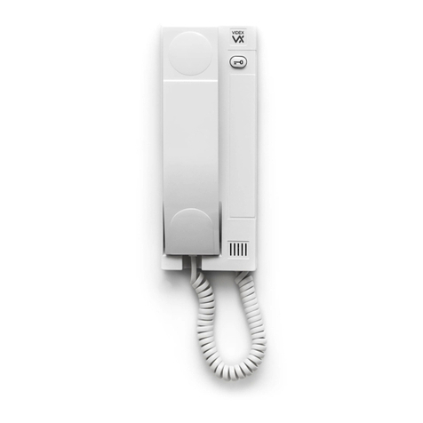
he Art.3011 audiophone is a smart line electronic call tone phone
and includes a lock release push buon and a 3 level call tone
volume switch and requires a minimum of 5 cores for connecon.
Audiophones & Apartment Staons
Art.3011
T
he Art.3111 electronic call tone phone includes a lock release
push buon and spare dry contact push to make buon for
other services. It also includes a 3 level call tone volume switch
and requires a minimum of 5 cores for connecon.
Art.3111
Terminal Funcon
1 Transmit speech to the door panel
2 Receive speech from the door panel
3 0V (Ground)
4 Electronic call tone input
5 Lock trigger (Switched 0V)
6 Not used
8 Dry contact switch
(for Art.3111 and Art.3112 only)
9
T
he Art.3112 electronic call tone phone includes a lock release
push buon and a spare dry contact push to make buon for
other services. Addionally it includes a slide mute switch to turn
the phone o when the tenant does not want to be disturbed. It
also includes a 3 level call tone volume switch. Like the Art.3011 and
Art.3111 it requires a minimum of 5 cores for connecon.
Art.3112
Art.3011
Terminal Funcon
1 Transmit speech to the door panel
2 Receive speech from the door panel
3 0V (Ground)
4 Electronic call tone input
5 Lock trigger (Switched 0V)
6 Not used
3000 Series Audiophones
Art.3111 Art.3112
terminal
connecons
terminal
connecons
3 level call
tone switch
120 VANDAL RESISTANT AUDIO AND VIDEO TECHNICAL MANUAL VER 1.0Page 16

5000 Series Apartment Staons
T
he Art.5112 audio apartment staon includes a talk buon and lock
release buon, two spare push buons, a three way privacy ON/OFF
switch and a call tone volume switch. It requires a minimum of 6 cores
for connecon and is available in three dierent nishes, white,
silver (/CR) and carbon bre (/CA).
Art.5112
Art.5112/CA
Art.5112/CR
Art.5112
The Art.5112 also has 3 control adjustment POTS:
Microphone Volume (VR2)
This POT adjusts the microphone speech volume from the apartment staon
towards the door intercom panel (rotate le to increase or right to decrease).
Conversaon Time (VR1)
This POT adjusts the conversaon me duraon from a minimum of 2 seconds
to a maximum of 45 seconds (rotate le to increase or right to decrease). This
me resets each me the speak buon is pressed.
Loudspeaker Volume (VR3)
This POT adjusts the loudspeaker speech volume from the intercom door panel
towards the apartment staon (rotate le to increase or right to decrease).
Terminal Signal Funcon Current Rang on +12V
1 2A Receive speech from the door panel Condion Current (mA)
2 4A Electronic call tone input Standby 0
3 +12V +12V DC power supply input During a call 0
4 GND Ground Privacy ON 13.5mA
5 1A Transmit speech to the door panel Live speech 55mA
6Spare push buon two (Switched 0V) Lock release 48mA
7 5A Lock Trigger (Switched 0V) Max 60mA
8Spare push buon one (Switched 0V)
9 +DOL Door open LED +posive power supply input
10 -DOL Door open LED –negave power supply input
control adjustment POTS
terminal
connecons
Page 17120 VANDAL RESISTANT AUDIO AND VIDEO TECHNICAL MANUAL VER 1.0

T
he Art.5118 audio apartment staon includes a talk buon and lock release
buon, one spare push buon, a privacy ON/OFF buon. It also has a two
buon speech line volume adjustment and a two buon melody volume
adjustment. It requires a minimum of 6 cores for connecon and is available
in three dierent nishes, white, silver (/CR) and carbon bre (/CA).
Art.5118 Art.5118/CA
Art.5118/CR
Art.5118
Speech and Melody Volume control
Speech line volume control.
This can be adjusted during a
conversaon when the speech
is live. Pressing the right buon
to increase or the le buon
to decrease the volume.
Melody volume control. This
can be adjusted when the
system is in standby. Pressing
the right buon to increase or
the le buon to decrease the
melody volume.
• Press and hold the two melody buons (for approximately 10 seconds) unl the unit plays the melody currently
stored and emits a beep.
• Press the melody buon again (le or right) to listen to the available melodies (maximum of 9).
• When the chosen melody has been reached, do not press any other buons, wait for approximately 3 seconds unl
the unit emits a beep.
• The new melody will be stored.
Art.5118 Programming
Programming the Melody (factory preset melody 1)
Programming the number of rings (factory preset = 6 rings)
• Press and hold the talk buon (for approximately 10 seconds) unl the unit emits a beep.
• Press the talk buon again for as many mes as the number of rings required, i.e. pressing the buon 6 mes
= 6 rings (maximum of 9 rings).
• Once the number of rings has been reached, do not press any other buons, wait for approximately 3 seconds unl
the unit emits a beep.
• The new number of rings will be stored.
Programming the privacy duraon me (factory preset = no me out, manual control)
• Press and hold the privacy buon (for approximately 10 seconds) unl the unit emits a beep.
• Press the privacy buon again to set the privacy me required. Each me the buon is pressed it will increase
the privacy duraon me by 15 minutes (starng from 0 up to a maximum of 20 hours, i.e. pressing the privacy
buon 8 mes = 2 hours up to a maximum of 80 presses for 20 hours).
• Once the required privacy duraon me has been reached, do not press any other buons, wait for approximately
3 seconds unl the unit emits a beep.
• The new privacy duraon me will be stored.
• To set the privacy with no me out, i.e. manual control, press and hold the privacy buon (for approximately
10 seconds) unl the unit emits a beep, do not press any other buons, wait for approximately 3 seconds unl the
unit emits a beep again.
• The new privacy duraon me will be stored.
120 VANDAL RESISTANT AUDIO AND VIDEO TECHNICAL MANUAL VER 1.0Page 18

Terminal Signal Funcon Current Rang on +12V
1 2A Receive speech from the door panel Condion Current (mA)
2 4A Electronic call tone input Standby 6mA
3 +12V +12V DC power supply input During a call 18-78mA
4 GND Ground Privacy ON 10mA
5 1A Transmit speech to the door panel Live speech 26mA
6 LB Local bell facility Lock release 30mA
7 5A Lock Trigger (Switched 0V) Max 80mA
8Spare push buon one (Switched 0V)
9 +DOL Door open LED +posive power supply input
10 -DOL Door open LED –negave power supply input
terminal
connecons
• Press and hold the lock buon (for approximately 10 seconds) unl the unit emits a beep.
• Press the lock buon again to set the door open me. Each me the buon is pressed it will increase the door
open me by 1 second (starng from 1 up to a maximum of 255 second, i.e. pressing the lock buon 10 mes
= 10 seconds to a maximum of 255 for 4 minutes and 15 seconds).
• Once the required door open me has been reached, do not press any other buons, wait for approximately 3
seconds unl the unit emits a beep.
• The new door open me will be stored*.
Programming the door open me (factory preset = 1 second)
Restoring all programming to factory preset
Please note that this operaon will restore all programming back to factory default sengs.
• Unplug the Art.5118 from the mounng pcb.
• Press and hold down the talk buon as the Art.5118 is plugged back into the mounng pcb.
• The LED close to the talk buon will ash once to conrm all sengs have been reset back to factory default.
• Release the talk buon.
VIDEOPHONES
Videophones & Handsfree Eclipse
3600 Series Videophones
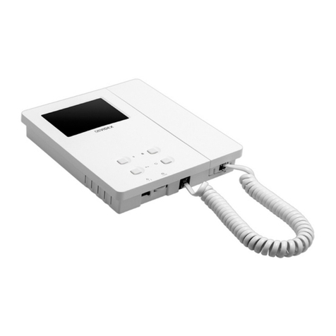
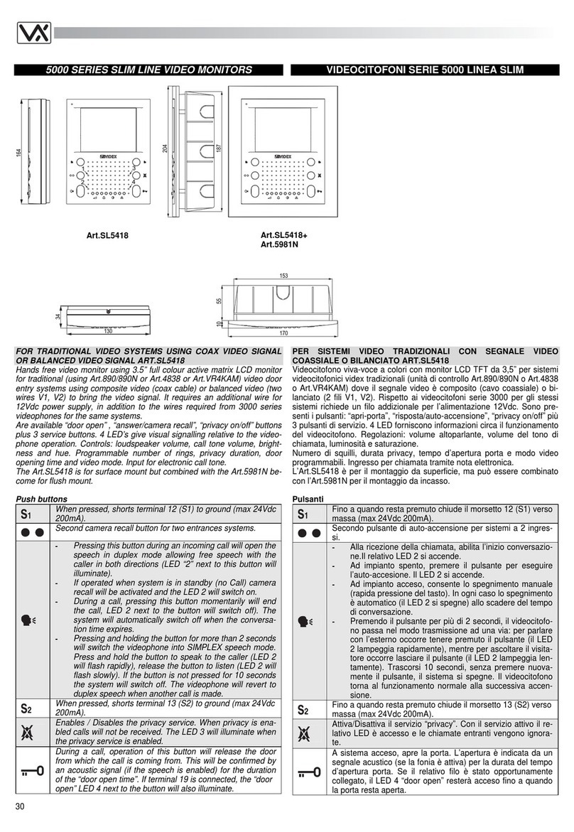
The Art.3612 colour videophone incorporates a colour 3.5” LCD
display and includes a lock release push buon, camera recall buon
and a spare push buon for other services or depending on seng
can act as a secondary camera recall buon on a two entrance video
system. Coax and non-coax (balanced) video can be used by seng the
relevant dip-switches on the rear of the monitor. An Art.5980 back
plate is required with this videophone.
Art.3612
Controls
• 3 level call tone volume (privacy posion plus 2 levels).
• Picture brightness adjustment.
• Picture hue adjustment.
Art.3612
Page 19120 VANDAL RESISTANT AUDIO AND VIDEO TECHNICAL MANUAL VER 1.0
*(NOTE: when used with the VR120 panel the door open me should
remain set to 1 second as the VR120 panel will control the door open
me by seng the dip-switches on the amplier, refer to page 5)

Minimum Cable Requirement:
• 9 cores + coax for video systems using coax video signal.
• 11 cores for video systems using balanced video signal.
Art.5980
terminal
connecons
Terminal Signal Funcon Current Rang on +20V
1 +12V +12V out to power video splier Condion Current (mA)
2 TV1 Camera recall Standby 0mA
3 TV2 Spare buon (see dip-switch sengs) During call 155mA
4 1 +20V power input Live speech 155mA
5 2 Door release command (Switched 0V) Lock release 160mA
6 3 Transmit speech to door panel Max 200mA
7 4 Receive speech from door panel
8 5 Speech ground
9 6 Video power ground
10 7 Local call tone input (electronic call tone)
11 V/V1 Coax centre core / V1 balanced video –negave sync
12 M/V2 Coax Screen / V2 balanced video +posive sync
13 R Speech common for intercommunicang systems
14 C Call tone input (electronic call tone)
15 - Speech ground for intercommunicang systems
16 T Service push buon common
17 Unused connecon
18 Unused connecon
19 12Vi +12Vdc power supply input to switch on the buon LED when the volume switch is in the
privacy posion
20 DOL +12Vdc power supply input to switch on the key buon LED
Connecons
call tone & privacy switch
handset connecon
brightness & hue adjustments
120 VANDAL RESISTANT AUDIO AND VIDEO TECHNICAL MANUAL VER 1.0Page 20
Table of contents
Other Videx Intercom System manuals

Videx
Videx 5178 User manual

Videx
Videx 4000 Series User manual

Videx
Videx 3187 User manual

Videx
Videx ESVK/6788 Series System manual

Videx
Videx 3000 Series User manual

Videx
Videx 6358 System manual

Videx
Videx 4812 User manual

Videx
Videx S6200MV User manual

Videx
Videx VK8K/6256 Series System manual

Videx
Videx 4000 Series User manual

Videx
Videx 2505 User manual

Videx
Videx VR5178 User manual

Videx
Videx 4843 User manual

Videx
Videx ESVK Series System manual

Videx
Videx Smart Series User manual

Videx
Videx 4000 Series User manual

Videx
Videx ESVK 6388 Series System manual

Videx
Videx VX2200 User manual

Videx
Videx 6200 Series User manual

Videx
Videx 940ST User manual