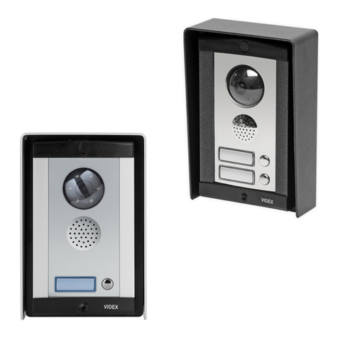
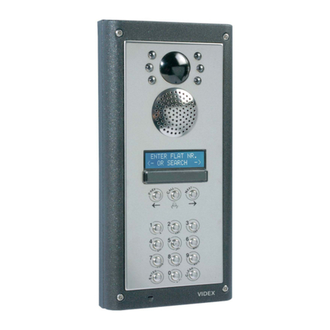
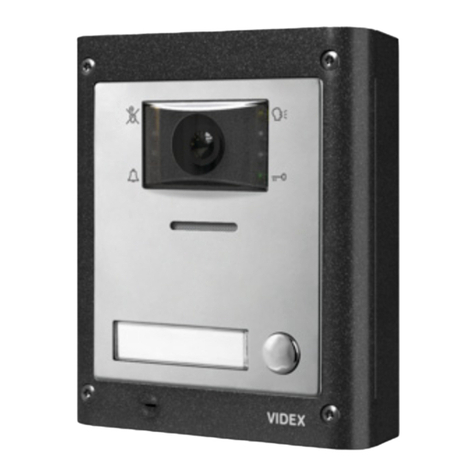
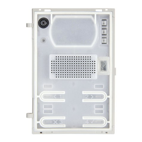
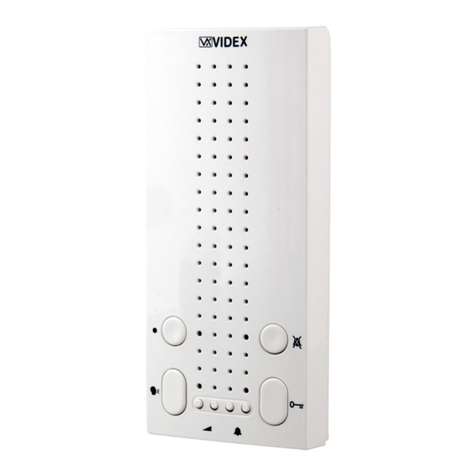
Videx 4000 Series 4384 User manual

66251850 - V2.7 - 15/05/21
- 1 -
4000 Series
Art.4384/4384X - Installation instructions
D
C
E
A
BB
Fig. 1 Front
ON
12345678
STEEL
MATTE
ALI
HIGH BRASS
GUN METAL
4384X-1
4384X-0
4384X-2
EXPANSION
BUTTONS
NC
VAUX
+C
C
NO
GND
PTE
BUS
BUS
+V2
GNDV
VID2
A
B
GND
RS485
4384-1
4384-0
4384-2
Made in Italy
G
F
O
H
I
L
M
N
Fig. 2 Back
DESCRIPTION
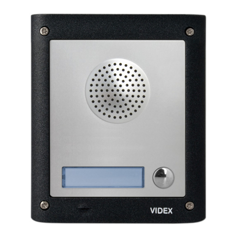
Speaker unit module for VX2300 digital system with built-in col-
our camera with autoiris lens and white light illumination LEDs.
Art.4384X versions are also equiped with a built-in proximity
key reader and programming modes.
The unit circuitry incorporates:
• The transmitting amplier with microphone and volume control;
• The receiving amplier with volume control;
• The audio balance circuit with“BALANCE”control;
• The enslavement relay to enable the electric lock (3 contacts:
common, normally open and normally closed). It can work
also as capacitor discharge to supply directly the electric lock;
• The call buttons from (0, 1 or 2 depending on the module version;
• The illumination LEDs for the card name holder;
• The camera comprised of illumination LEDs.
LEGEND
ACamera with illumination
LEDs
BOperation LEDs
CLoudspeaker
DCard name holder with built
in-in proximity key reader
(only Art.4384X versions)
ECall push button
FCamera horizontal and
vertical adjustment (not
available in Wide Angle
versions)
GBalance
HLoudspeaker volume
IMicrophone volume
L8 way dip-switch
MRS485 connection terminals
(only Art.4384X versions)
NIDC male connectors
OConnection terminals
AVAILABLE VERSIONS
Art.4384-0 Art.4384X-0
1
Art.4384-1
Art.4384X-1
1
2
Art.4384-2
Art.4384X-2
LEDS
The rst LED (red), if switched ON, indicates that it is
not possible to make a call because a call or a conver-
sation is in progress (from the outdoor station from
which you are calling or from another outdoor station
on systems with multiple entrances).
The second LED (red), if switched ON, indicates that a
call is in progress. The LED will be switched OFF when
the call is answered.
The third LED (yellow), if switched ON, indicates that it is
possible to speak.The LED will be switched OFF at the end
of conversation (or at the end of the conversation time).
The fourth LED (green), if switched ON, means that the
door lock has been operated. It will be switched OFF at
the end of the“door opening”time.
CONTROLS
Balance
Prevent Larsen eect on bidirectional audio conversation.
Loudspeaker volume
Adjust the loudspeaker volume.
Rotate clockwise to increase or anti-clockwise to decrease
Microphone volume
Adjust the microphone volume.
Rotate clockwise to increase or anti-clockwise to decrease
Art.4384 Speaker unit with built-in camera
Art.4384X Speaker unit with built-in camera & proximity key reader

66251850 - V2.7 - 15/05/21
- 2 -
4000 Series
Art.4384/4384X - Installation instructions
PROGRAMMING
The programming consists of the following settings:
• Unit ID (1..15);
• Door opening time (2 or 6 seconds);
• Conversation time (1 or 2 minutes);
• Addressing order of the buttons.
• Main camera selection for Art.4384 versions or programming mode for Art.4384X versions.
The settings are carried out through the 8 way dip-switch (reference Lon Fig. 2) accessible from the rear side of the module.
PROGRAMMING THE UNIT ID
Switch Nr.1 Nr.2 Nr.3 Nr.4 ID
ON
1 3 5 72 4 6 8 OFF OFF OFF OFF 1
ON
1 3 5 72 4 6 8 ON OFF OFF OFF 2
ON
1 3 5 72 4 6 8 OFF ON OFF OFF 3
ON
1 3 5 72 4 6 8 ON ON OFF OFF 4
ON
1 3 5 72 4 6 8 OFF OFF ON OFF 5
ON
1 3 5 72 4 6 8 ON OFF ON OFF 6
ON
1 3 5 72 4 6 8 OFF ON ON OFF 7
ON
1 3 5 72 4 6 8 ON ON ON OFF 8
ON
1 3 5 72 4 6 8 OFF OFF OFF ON 9
ON
1 3 5 72 4 6 8 ON OFF OFF ON 10
ON
1 3 5 72 4 6 8 OFF ON OFF ON 11
ON
1 3 5 72 4 6 8 ON OFF ON ON 12
ON
1 3 5 72 4 6 8 OFF OFF ON ON 13
ON
1 3 5 72 4 6 8 ON OFF ON ON 14
ON
1 3 5 72 4 6 8 OFF ON ON ON 15
ON
1 3 5 72 4 6 8 ON ON ON ON 16
PROGRAMMING THE DOOR OPENING TIME
Switch Nr.5 Setting Up
ON
1 3 572 4 6 8 OFF = 2 seconds
ON
1 3 572 4 6 8 ON = 6 seconds
PROGRAMMING THE CONVERSATION TIME
Switch Nr.6 Setting Up
ON
1 3 5 72 4 68OFF = 1 minute
ON
1 3 5 72 4 68ON = 2 minutes
PROGRAMMINGTHE ADDRESSING ORDER OFTHE BUTTONS
Switch Nr.7 Setting Up
Button matrix Internal buttons
ON
1 3 5 72 4 6 8 OFF = 1 - 40 = 1, 2
ON
1 3 5 72 4 6 8 ON = 41 - 80 = 41, 42
PROGRAMMING THE MAIN CAMERA SELECTION
ONLY ART.4384 VERSIONS
Switch Nr.8 Setting Up
ON
1 3 5 72 4 6 8OFF = Main camera internal
ON
1 3 5 72 4 6 8ON = Main camera external
PROGRAMMING MODES ONLY ART.4384X VERSIONS
Switch 8 sets the programming mode: "Standard" (switch in OFF
position) or "Advanced" (switch in ON position).
In "Standard" mode settings are made by switches from 1 to 7.
In "Advanced" mode all programming is made via the "VX2X00
Programmer" PC software connected to RS485 via an Art.481 in-
terface. Please note that in this case the programming made by
switches from 1 to 7 wil be ignored.
Switch Nr.8 Setting Up
ON
1 3 5 72 4 6 8OFF "Standard" programming mode
ON
1 3 5 72 4 6 8ON "Advanced" programming mode
Art.4384 Speaker unit with built-in camera
Art.4384X Speaker unit with built-in camera & proximity key reader

66251850 - V2.7 - 15/05/21
- 3 -
4000 Series
Art.4384/4384X - Installation instructions
Art.4384 Speaker unit with built-in camera
Art.4384X Speaker unit with built-in camera & proximity key reader
RS485 CONNECTION
With switch 8 in ON position the
module can be connected using an
RS485 bus connection via an RS485
to USB converter (Art.481) as shown
in Fig. 3.
This method of connection can be
used for programming and setup of
the module.
Over distances shorter than 500mt
the bus termination jumper on the
Art.481 can be set to the OPEN po-
sition.
ON
12345678
STEEL
MATTE
ALI
HIGH BRASS
GUN METAL
4384X-1
4384X-0
4384X-2
EXPANSION
BUTTONS
NC
VAUX
+C
C
NO
GND
PTE
BUS
BUS
+V2
GNDV
VID2
A
B
GND
RS485
4384-1
4384-0
4384-2
Made in Italy
485 / 232
RS-485
USB-PC
A B GND
RS-232
Art. 481
USB-Serial Converter
Open
Close
BUS
Termination
switch to RS485 position
RS485 cable
USB cable
PC
BUS termination jumper
in the closed position
Fig. 3
404x FLAT CABLE CONNECTION
To power the button module connect one of the inbuilt IDC male connectors to the IDC male connector of the camera unit mod-
ule through the at cable provided. Further buttons expansion modules can be connected to the free IDC male connector of the
previous expansion module (Fig. 4).
OR
Art.CFL17
17 cm lenght at cable
(Supplied)
Art.CFL45
45 cm lenght at cable
(to be ordered separately
)
Fig. 4
J2 AND J1 JUMPERS BACKLIT LEDS SETTINGS
For proper functioning please set J2 and J1 jumpers of any connected button expansion module Art.404x as shown in the table below.
NOTE: when more modules are connected, following the connection order, every two modules, the previous must be set as module
1 while the next must be set as module 2.
USING ONE SINGLE EXPANSION BUTTON MODULE
J2 J1
B A B A
USING A COUPLE EXPANSION BUTTON MODULES
1
2
Expansion button module 1
J2 J1
B A B A
Art.4384 - Art.4384X
Expansion button module 2
J2 J1
B A B A
NOTE: to connect more than 2 expansion button modules,
please refer also to the installation diagrams.

66251850 - V2.7 - 15/05/21
- 4 -
4000 Series
Art.4384/4384X - Installation instructions
HOW TO CONNECT AN ELECTRIC LOCK
The“door-open”relay can operate either as “dry contact” or “capacitive discharge”mode.
• In “dry contact” operation mode the relay works in a traditional way, a power supply or a power source is needed to operate the
lock (12-24Vac/dc 2A max), and activation lasts according to the door opening time programmed.
• In “capacitive discharge” operation mode the relay’s contacts, when active, supply directly the lock (12Vac/dc 1A max) for a mo-
ment. You don’t need a power supply for the lock and the door opening time programmed does not aect the activation time.
A possibile deterioration of the mechanical performance of the electric lock, might cause the“capacitive discharge” to malfunction
in time. In case the electric lock is used in very dusty environments or in peculiar climate conditions, we suggest to use the “open
door”relay in“dry contact” mode.
13V
230V
50/60 Hz
ART.321
230V
12Vac
12Vac 1.6A Max using Art.321
24Vac/dc 2A Max using other power supplies
Using CAPACITIVE
DISCHARGE
Using separate P.S.U.
4653
2
1
ON
Unit ID:
87
EXPANSION
BUTTONS
Art.4384-1
1
4653
2
1
ON
Unit ID:
87
EXPANSION
BUTTONS
Art.4384-1
1
Videx Electronics S.p.A.
Via del Lavoro 1, 63846 Monte Giberto (FM)
Phone: +39 0734 631669 - Fax +39 0734 631669
www.videx.it - info@videx.it
Autore:
Data modifica:
Data creazione:Title:
Notes:
Titolo:
Note: Cod.File:
Foglio
/11
Marco Rongoni
esvk-
g
005.dw
g
13/06/2019
13/06/2019
12Vac/dc 1A Max
Fig. 5 Using capacitive discharge
13V
230V
50/60 Hz
ART.321
230V
12Vac
12Vac 1.6A Max using Art.321
24Vac/dc 2A Max using other power supplies
Using CAPACITIVE
DISCHARGE Using separate P.S.U.
4653
2
1
ON
Unit ID:
87
EXPANSION
BUTTONS
Art.4384-1
1
4653
2
1
ON
Unit ID:
87
EXPANSION
BUTTONS
Art.4384-1
1
Videx Electronics S.p.A.
Via del Lavoro 1, 63846 Monte Giberto (FM)
Phone: +39 0734 631669 - Fax +39 0734 631669
www.videx.it - info@videx.it
Autore:
Data modifica:
Data creazione:Title:
Notes:
Titolo:
Note: Cod.File:
Foglio
/11
Marco Rongoni
esvk-
g
005.dw
g
13/06/2019
13/06/2019
12Vac 1.6A Max using Art.321
24Vac/dc 2A Max using other power supplies
Fig. 6 Using separate P.S.U.
OPERATION
Once the device has been programmed and connected correctly, it will generate upon each pressing of a push button, a code correspond-
ing to the PHONE ID (address programmed on the 8 way dip-switch inside each telephone) of the telephone being called.
TO CALL A USER
Press the relevant button to call the user: 2 quick beeps will indicate if the system is busy, otherwise the call will be signalled by a
slow intermittent acoustic signal until the call is answered, the conversation time expires (programmable time) or the call is inter-
rupted by pressing a push button for a minimum of 2 seconds.
A short intermittent acoustic signal plus the relevant LED switched ON indicates that the door is open. If a wrong push button is
pressed or if there is no answer, a new call will cancel the previous one.
MOUNTING NOTES
When an expansion button module (Art.404x)
is usedcombined withspeaker units withinbuilt
camera (Art.4384-1, Art.4384-2, Art. 4384X-1,
Art. 4384X-2) remember to set the expansion
modules properly in order to avoid overwriting
the addresses; indeed the inbuilt buttons ad-
dresses are already set (Fig. 7).
1
6
7
8
9
10
1
2
6
7
8
9
10
Art.4384 -Art.4384X
switch
Nr.7
ON
12345678OFF
Art.404x jumper
n=5
R
Fig. 7
Art.4384 Speaker unit with built-in camera
Art.4384X Speaker unit with built-in camera & proximity key reader

66251850 - V2.7 - 15/05/21
- 5 -
4000 Series
Art.4384/4384X - Installation instructions
PROGRAMMING TAGS ONLY ART.4384X VERSIONS
MASTER TAG
The external module is supplied with a master tag. The master tag is programmed in-factory, it is white to easily stand out. This tag
enables user tags to be programmed or cleared.
If the master tag is lost, a new one will have to be ordered and a specic procedure performed to program it on the external module.
In this instance, it will be necessary to reprogram all the user tags.
USER TAG
The user tags can be programmed on the external module using the master tag to access programming mode:
1.Place the master tag in front of the tag reader.
↪The external module emits two high-pitched “bip”.
BIP BIP
2.Press the call button (the lower call button in the case of a 2-button external module).
↪The external module emits a low-pitched continuous “beeping” sound.
BIIIIIIP
3.Release the call button.
↪The low-pitched “beeping” sound stops.
4.Place the user tag to be programmed in front of the tag reader.
↪The external module emits a high-pitched “beeping” sound, the tag is programmed. If you do
not remove the tag quickly, may be emitted the alert for an already programmed tag.
BIP
5.Repeat the step 4 for each tag to program.
Note: the external module emits three low-pitched “beeping” sounds if an already programmed
tag is placed in front of the tag reader.
BIP BIP BIP
Note: the external module emits three high-pitched “beeping” sounds to indicate that its
memory is full (50 tags maximum). In this instance, it is not possible to program new tags.
BIP BIP BIP
6.To exit programming mode:
» place the master tag in front of the tag reader, or
» wait 10 seconds after the most recent programming operation.
↪ The external module emits two low-pitched “beeping” sounds in order to indicate
that it is in operational mode.
BIP BIP
USING TAGS
Place a tag in front of the tag reader:
↪If the tag is programmed, the external module emits two high-pitched “beeping” sounds
and its relay is activated.
BIP BIP
↪If the tag is not programmed, the external module emits three low-pitched “beeping”
sounds and its relay is not activated.
BIP BIP BIP
CLEARING USER TAGS
The following procedure will clear the programming on all user tags.
Clearing the user tag programming is carried out on the external module using the master tag to run the procedure:
1.Place the master tag in front of the tag reader.
↪The external module emits two high-pitched “bip”.
BIP BIP
2.Press the call button (the lower call button in the case of an external 2-button module) BIP.
↪The external module emits a low-pitched continuous “beeping” sound.
BIIIIIIP
3.Release the call button.
↪The low-pitched “beeping” sound stops.
4.Press and hold down the call button and place the master tag in front of the tag reader.
↪The external module emitts two low-pitched “beeping” sounds, all user tags have been
cleared and the external module exits programming mode.
BIP BIP
Art.4384 Speaker unit with built-in camera
Art.4384X Speaker unit with built-in camera & proximity key reader

66251850 - V2.7 - 15/05/21
- 6 -
4000 Series
Art.4384/4384X - Installation instructions
REPROGRAMMING A MASTER TAGS
If the master tag is lost or damaged, a new one can be programmed using the following procedure:
1.Switch o the power.
2.Open the external module housing.
3.Bridge the PTE and GND terminals or press and hold down the“press to exit”button, if this
is wired to the external module (refer to the external module's instructions).
ON
12345678
STEEL
MATTE
ALI
HIGH BRASS
GUN METAL
4384X-1
4384X-0
4384X-2
EXPANSION
BUTTONS
NC
VAUX
+C
C
NO
GND
PTE
BUS
BUS
+V2
GNDV
VID2
A
B
GND
RS485
4384-1
4384-0
4384-2
Made in Italy
4.Switch the power back on.
↪The external module emits a high-pitched “beeping” sound.
BIP
5. Remove the short between the PTE and GND terminals or release the“press to exit”button.
↪The external module emits a high-pitched "beeping" sound.
BIP
6.Place the master tag in front of the tag reader.
↪The external module emits two high-pitched “beeping” sounds, then two low-pitched
“beeping” sounds, the master tag is programmed, all user tags have been deprogrammed
and the external module exits programming mode.
BIP BIP
BIP BIP
7.Close the external module's housing.
HOW TO REMOVE/INSERT THE CARD NAME HOLDER
• To avoid damage to the module front plate, mask the side that
will be in contact with the screwdriver blade;
• Insert the screwdriver (at side) into the card-holder hole as
shown in Fig. 8;
• Move the screwdriver to the left as shown in Fig. 9 to extract
the card name holder;
• Edit the card name then replace it inside the holder and ret:
insert the holder inside its housing from the left or right side
then push the other side until it clips into place. Fig. 8 Fig. 9
ADHESIVE GASKET PLACEMENT
Apply the Yseal as shown in Fig. 10.
ANTITAMPERING LOCKS FIXING
Fit the anti-tampering locks Was shown in Fig. 11.
Y
G
Fig. 10
W
Fig. 11
Art.4384 Speaker unit with built-in camera
Art.4384X Speaker unit with built-in camera & proximity key reader

66251850 - V2.7 - 15/05/21
- 7 -
4000 Series
Art.4384/4384X - Installation instructions
CAMERA NOTES
MAXIMUM ILLUMINATION DISTANCE
FROM CAMERA AT NIGHT
The illumination LED’s within the camera
will illuminate the visitor when they are
within 50cm of the camera.
MAX 50 cm
FIELDS OFVIEW
The elds of view for standard camera are 55° for vertical angle and 115° for horizontal angle
while for Wide Angle camera are 80° for vertical angle and 170° for horizontal angle.
195 cm
80° 55°
170 cm
100 cm
75 cm
135 cm
70 cm
Vertical angle
170°
115°
180 cm
105 cm
70 cm
Horizontal angle
Standard camera Wide Angle camera
CONNECTION TERMINALS SIGNALS
ART.4384 VERSIONS
VID2 Video signal input (coax centre core)
GNDV Video signal ground (coax screen and 0V to camera)
+V2 Output to supply the external camera
if necessary
Max 12Vdc
150mA
BUS BUS Connection terminals
BUS
PTE “Push to exit”active low input
GND Ground
NO Door open relay normally open contact Max 12-24
Vac/dc 2A
CDoor open relay common contact
+C Electric lock capacitor discharge output
VAUX
35Vdc power supply input/output.
In case the use of Art.2321, the module is powered
locally and not from the BUS.
It can be used as a source power (up to 20mA) to
drive the Art.4846 module backlight.
NC Door open relay normally closed
contact
Max 12-24
Vac/dc 2A
ART.4384X VERSIONS
VID2 Video signal input (coax centre core)
GNDV Video signal ground (coax screen and 0V to camera)
+V2 Output to supply the external camera
if necessary
Max 12Vdc
150mA
BUS BUS Connection terminals
BUS
PTE “Push to exit”active low input
GND Ground
NO Door open relay normally open contact Max 12-24
Vac/dc 2A
CDoor open relay common contact
+C Electric lock capacitor discharge output
VAUX
35Vdc power supply input/output.
In case the use of Art.2321, the module is powered
locally and not from the BUS.
It can be used as a source power (up to 20mA) to
drive the Art.4846 module backlight.
NC Door open relay normally closed
contact
Max 12-24
Vac/dc 2A
GND Ground
BRS-485 serial interface
A
CLEANING OF THE PLATE
Use a clean and soft cloth. Use moderate warm water or non-ag-
gressive cleansers.
Do not use:
• abrasive liquids;
• chlorine-based liquids;
• metal cleaning products.
TECHNICAL SPECIFICATIONS
Call buttons: Up to 94
Power consumption: Stand-by: 60+10mA for each 404x
Operating 100+10mA for each 404x
Peak: 250mA
Working voltage: Supplied by the BUS line
Working temperature: -20 +60 °C
Art.4384 Speaker unit with built-in camera
Art.4384X Speaker unit with built-in camera & proximity key reader

66251850 - V2.7 - 15/05/21
- 8 -
Serie 4000
Art.4384/4384X - Istruzioni di installazione
D
C
E
A
BB
Fig. 1 Fronte
ON
12345678
STEEL
MATTE
ALI
HIGH BRASS
GUN METAL
4384X-1
4384X-0
4384X-2
EXPANSION
BUTTONS
NC
VAUX
+C
C
NO
GND
PTE
BUS
BUS
+V2
GNDV
VID2
A
B
GND
RS485
4384-1
4384-0
4384-2
Made in Italy
G
F
O
H
I
L
M
N
Fig. 2 Retro
DESCRIZIONE
Modulo portiere elettrico per sistema digitale VX2300 con teleca-
mera incorporata a colori autofocus comprensiva di LED d’illumina-
zione a luce bianca. Le versioni Art.4384X sono inoltre equipaggiate
con un lettore di chiavi di prossimità integrato e l'impostazione di
modalità di programmazione.
L’elettronica del modulo incorpora:
• L’amplicatore di trasmissione con microfono e controllo del volume;
• L’amplicatore di ricezione con controllo del volume;
• Il circuito di bilanciamento dell’audio“BALANCE”;
• Il relè di asservimento per l’attivazione della serratura elettrica
(3 contatti puliti: comune, normalmente aperto e normalmente
chiuso). Il relè può operare anche nel modo “scarica capacitiva”
alimentando direttamente la serratura;
• I pulsanti di chiamata (0, 1 o 2 in base alla versione);
• I LED di illuminazione del porta cartellino;
• La telecamera comprensiva dei LED d’illuminazione.
LEGENDA
ATelecamera e LED di illumi-
nazione
BLED di funzionamento
CAltoparlante
DPorta-cartellino con letto-
re di chiavi di prossimità
integrato (solo versioni
Art.4384X)
EPulsante di chiamata
FRegolazione orientamento
telecamera in orizzontale e
verticale (non disponibile
nelle versioni Wide Angle)
GBilanciamento
HVolume altoparlante
IVolume microfono
LDip-switch a 8 vie
MMorsetteria di connes-
sione RS485 (solo versioni
Art.4384X)
NConnettore IDC maschio
OMorsettiera di connessione
VERSIONI DISPONIBILI
Art.4384-0 Art.4384X-0
1
Art.4384-1
Art.4384X-1
1
2
Art.4384-2
Art.4384X-2
LED
Il primo LED (rosso) indica, se acceso, che non è possibi-
le eettuare la chiamata perché è in corso una chiamata
o una conversazione (dall’ingresso dal quale si sta chia-
mando o da un altro ingresso in caso d’ingressi multipli).
Chiusa la conversazione, il LED si spegne segnalando che
è possibile fare una nuova chiamata.
Il secondo LED (rosso) indica, se acceso, che è in corso
una chiamata. Il LED si spegne alla risposta dell’utente
chiamato.
Il terzo LED (verde) indica, se acceso, che è possibile
parlare con l’utente chiamato. Il LED si spegne a ne
conversazione.
Il quarto LED (giallo) contrassegnato dal simbolo , se ac-
ceso, indica che sta avvenendo l’apertura della porta. Il
LED si spegne allo scadere del tempo di apertura porta.
REGOLAZIONI
Bilanciamento
Previene l’eetto Larsen su conversazione audio bidirezionale.
Volume altoparlante
Regolazione del volume dell’altopalralte.
Ruotare in senso orario per aumentare o antiorario per diminuire
Volume microfono
Regolazione del volume del microfono.
Ruotare in senso orario per aumentare o antiorario per diminuire
Art.4384X Portiere elettrico con telecamera e lettore di prossimità incorporati
Art.4384 Portiere elettrico con telecamera incorporata

66251850 - V2.7 - 15/05/21
- 9 -
Serie 4000
Art.4384/4384X - Istruzioni di installazione
PROGRAMMAZIONE
La programmazione consiste nei seguenti settaggi:
• Il numero del dispositivo (1..15);
• Il tempo di apertura porta (2 o 6 secondi);
• Il tempo di apertura porta (1 o 2 minuti);
• Ordine indirizzi;
• Selezione telecamera principale per le versioni Art.4384 oppure la modalità di programmazione per le versioni Art.4384X.
Le impostazioni vengono eettuate tramite il dip-switch a 8 vie (riferimento LFig. 2) accessibile nella parte posteriore del modulo.
PROGRAMMAZIONE DEL NUMERO DI DISPOSITIVO
Switch Nr.1 Nr.2 Nr.3 Nr.4 ID
ON
1 3 5 72 4 6 8 OFF OFF OFF OFF 1
ON
1 3 5 72 4 6 8 ON OFF OFF OFF 2
ON
1 3 5 72 4 6 8 OFF ON OFF OFF 3
ON
1 3 5 72 4 6 8 ON ON OFF OFF 4
ON
1 3 5 72 4 6 8 OFF OFF ON OFF 5
ON
1 3 5 72 4 6 8 ON OFF ON OFF 6
ON
1 3 5 72 4 6 8 OFF ON ON OFF 7
ON
1 3 5 72 4 6 8 ON ON ON OFF 8
ON
1 3 5 72 4 6 8 OFF OFF OFF ON 9
ON
1 3 5 72 4 6 8 ON OFF OFF ON 10
ON
1 3 5 72 4 6 8 OFF ON OFF ON 11
ON
1 3 5 72 4 6 8 ON OFF ON ON 12
ON
1 3 5 72 4 6 8 OFF OFF ON ON 13
ON
1 3 5 72 4 6 8 ON OFF ON ON 14
ON
1 3 5 72 4 6 8 OFF ON ON ON 15
ON
1 3 5 72 4 6 8 ON ON ON ON 16
PROGRAMMAZIONE DEL TEMPO DI APERTURA PORTA
Switch Nr.5 Impostazione
ON
1 3 572 4 6 8 OFF = 2 secondi
ON
1 3 572 4 6 8 ON = 6 secondi
PROGRAMMAZIONE DEL TEMPO DI CONVERSAZIONE
Switch Nr.6 Impostazione
ON
1 3 5 72 4 68OFF = 1 minuto
ON
1 3 5 72 4 68ON = 2 minuti
PROGRAMMAZIONE ORDINE INDIRIZZI
Switch Nr.7 Impostazione
Matrice pulsanti
Pulsanti incorporati
ON
1 3 5 72 4 6 8 OFF = 1 - 40 = 1, 2
ON
1 3 5 72 4 6 8 ON = 41 - 80 = 41, 42
PROGRAMMAZIONE SELEZIONE TELECAMERA PRINCIPALE
SOLO VERSIONI ART.4384
Switch Nr.8 Impostazione
ON
1 3 5 72 4 6 8OFF = Telecamera principale interna
ON
1 3 5 72 4 6 8ON = Telecamera principale esterna
MODALITÀ DI PROGRAMMAZIONE SOLOVERSIONI ART.4384X
Switch Nr.8 Impostazione
ON
1 3 5 72 4 6 8OFF Modalità di programmazione
"Standard"
ON
1 3 5 72 4 6 8ON Modalità di programmazione
"Avanzata"
Lo switch 8 imposta la modalità di programmazione: "Standard"
(switch in posizione OFF) o "Avanzata" (switch in posizione ON).
In modalità "Standard" sono valide le impostazioni eettuate
tramite gli switch da 1 a 7.
In modalità "Avanzata" sono valide le programmazioni fatte tra-
mite il programma per PC "VX2X00 Programmer" collegato via
RS485 del dispositivo attraverso l'interfaccia Art.481.
Si prega di notare che nel secondo caso la programmazione
eettuata tramite gli switch da 1 a 7 sarà ignorata.
Art.4384 Portiere elettrico con telecamera incorporata
Art.4384X Portiere elettrico con telecamera e lettore di prossimità incorporati
66251850 - V2.7 - 15/05/21
- 10 -
Serie 4000
Art.4384/4384X - Istruzioni di installazione
CONNESSIONE RS485
Con lo switch 8 in posizione ON il
modulo può essere collegato utiliz-
zando un collegamento bus RS485
tramite un convertitore RS485 a USB
(Art.481), come mostrato Fig. 3.
Questo metodo di connessione può
essere utilizzato per la programma-
zione e l’impostazione del modulo.
Su distanze minori di 500m il jumper
di terminazione bus sull’Art. 481 può
essere impostato in posizione APERTA.
ON
12345678
STEEL
MATTE
ALI
HIGH BRASS
GUN METAL
4384X-1
4384X-0
4384X-2
EXPANSION
BUTTONS
NC
VAUX
+C
C
NO
GND
PTE
BUS
BUS
+V2
GNDV
VID2
A
B
GND
RS485
4384-1
4384-0
4384-2
Made in Italy
485 / 232
RS-485
USB-PC
A B GND
RS-232
Art. 481
USB-Serial Converter
Open
Close
BUS
Termination
Passare alla posizione RS485
Cavo RS485
Cavo USB
PC
Jumper di terminazione
bus RS485 in posizione
chiusa
Fig. 3
COLLEGAMENTO FLAT CABLE 404x
Per dare alimentazione al modulo collegare uno dei connettori maschio IDC al connettore maschio IDC del modulo portiere elettrico
attraverso il cavo at fornito a corredo. Ulteriori moduli di espansione possono essere collegati tramite il connettore mschio IDC libero
del precedento modulo d’espansione
(Fig. 4).
O
Art.CFL17
Cavo at lunghezza 17 cm
(fornito a corredo)
Art.CFL45
Cavo at lunghezza 45 cm
(da ordinare separatamente)
Fig. 4
IMPOSTAZIONI JUMPER J2 E J1 PER LED DI RETROILLUMINAZIONE
Per un corretto funzionamento impostare i jumper J2 e J1 di ogni modulo espansione pulsantiera connesso Art.404x come mo-
strato nelle tabelle sottostante.
NOTA: quando più moduli sono collegati, seguendo l'ordine di connessione, ogni due moduli, il precedente deve essere imposto
come modulo uno mentre il successivo come modulo 2.
UTILIZZO CON UN SINGOLO MODULO ESPANSIONE PULSANTIERA
J2 J1
B A B A
UTILIZZO CON UNA COPPIA DI MODULI ESPANSIONE PULSANTIERA
1
2
Modulo espansione pulsantiera 1
J2 J1
B A B A
Art.4384 - Art.4384X
Modulo espansione pulsantiera 2
J2 J1
B A B A
NOTA: per collegare più di due moduli di espansione pulsanti-
era, fare riferimento agli schemi di installazione.
Art.4384 Portiere elettrico con telecamera incorporata
Art.4384X Portiere elettrico con telecamera e lettore di prossimità incorporati
66251850 - V2.7 - 15/05/21
- 11 -
Serie 4000
Art.4384/4384X - Istruzioni di installazione
COME COLLEGARE LA SERRATURA ELETTRICA
Il relé“apri-porta”può operare nel modo“contatti puliti” o nel modo “scarica capacitiva”:
• Nel modo“contatti puliti”il relé funziona nella maniera classica, è necessario un alimentatore o una fonte di alimentazione per la serratura (12-
24Vac/dc 2A max) e la durata di attivazione dipende dal tempo d’apertura porta programmato.
• Nel modo“scarica capacitiva”i contatti del relè, al momento dell’attivazione, alimentano direttamente la serratura (12Vac/dc 1A max) per
un istante. Non è richiesto un alimentatore per la serratura e il tempo d’apertura porta programmato non inuisce sul tempo di attivazione.
A causa del possibile deterioramento delle prestazioni meccaniche della serratura elettrica, la“scarica capacitiva”, col tempo, può incor-
rere in malfunzionamenti dovuti appunto alla serratura. Nel caso in cui la serratura venga impiegata in ambienti particolarmente pol-
verosi o comunque particolarmente esposti agli agenti atmosferici, si consiglia di utilizzare il relè“apri-porta”nel modo“contatti puliti”.
13V
230V
50/60 Hz
ART.321
230V
12Vac
12Vac 1.6A Max using Art.321
24Vac/dc 2A Max using other power supplies
Using CAPACITIVE
DISCHARGE
Using separate P.S.U.
4653
2
1
ON
Unit ID:
87
EXPANSION
BUTTONS
Art.4384-1
1
4653
2
1
ON
Unit ID:
87
EXPANSION
BUTTONS
Art.4384-1
1
Videx Electronics S.p.A.
Via del Lavoro 1, 63846 Monte Giberto (FM)
Phone: +39 0734 631669 - Fax +39 0734 631669
www.videx.it - info@videx.it
Autore:
Data modifica:
Data creazione:Title:
Notes:
Titolo:
Note: Cod.File:
Foglio
/11
Marco Rongoni
esvk-
g
005.dw
g
13/06/2019
13/06/2019
12Vac/dc 1A Max
Fig. 5 Utilizzo con scarica capacitiva
13V
230V
50/60 Hz
ART.321
230V
12Vac
12Vac 1.6A Max using Art.321
24Vac/dc 2A Max using other power supplies
Using CAPACITIVE
DISCHARGE Using separate P.S.U.
4653
2
1
ON
Unit ID:
87
EXPANSION
BUTTONS
Art.4384-1
1
4653
2
1
ON
Unit ID:
87
EXPANSION
BUTTONS
Art.4384-1
1
Videx Electronics S.p.A.
Via del Lavoro 1, 63846 Monte Giberto (FM)
Phone: +39 0734 631669 - Fax +39 0734 631669
www.videx.it - info@videx.it
Autore:
Data modifica:
Data creazione:Title:
Notes:
Titolo:
Note: Cod.File:
Foglio
/11
Marco Rongoni
esvk-
g
005.dw
g
13/06/2019
13/06/2019
12Vac 1.6A Max utilizzando Art.321
24Vac/dc 2A Max utilizzando altri alimentatori
Fig. 6 Utilizzo con alimentatore separato
FUNZIONAMENTO
Il dispositivo, dopo le opportune impostazioni e gli adeguati collegamenti dei pulsanti, genera, alla pressione di ciascun pulsante
collegato, un codice che corrisponde all’ID CITOFONO (l’indirizzo programmato sul dip-switch ad 8 vie interno alle periferiche) del
citofono o videocitofono situato all’interno dell’appartamento che si desidera chiamare.
PER CHIAMARE UN UTENTE
Premere il pulsante relativo all’utente che si desidera chiamare: se il sistema è occupato sarà segnalato da 5 beep rapidi, altrimenti la
chiamata sarà scandita da un segnale acustico a lenta intermittenza, interrotto dalla risposta dell’utente o dallo scadere dell’intervallo
del tempo di conversazione (tempo programmabile) o dalla pressione prolungata (2sec circa) di un pulsante di chiamata. L’apertura
della porta è segnalata da un breve segnale acustico intermittente e dall’accensione del relativo LED. In caso di pressione di un tasto
sbagliato o di mancata risposta, una nuova chiamata può cancellare quella precedente.
NOTE DI INSTALLAZIONE
Quando si utilizzano moduli d'espansione
pulsantiera (Art. 404x) in abbinamento a
portieri con pulsanti incorporati (Art.4384-1,
Art.4384-2, Art.4384X-1, Art.4384X-2), con-
gurare opportunamente i moduli d'espan-
sione pulsantiera in maniera tale da evitare
sovrapposizione di indirizzi di chiamata in
quanto gli indirizzi dei pulsanti incorporati
sono ssi (Fig. 7).
1
6
7
8
9
10
1
2
6
7
8
9
10
Switch
Art.4384 -Art.4384X
Nr.7
ON
12345678OFF
Jumper Art.404x
n=5
R
Fig. 7
Art.4384 Portiere elettrico con telecamera incorporata
Art.4384X Portiere elettrico con telecamera e lettore di prossimità incorporati
66251850 - V2.7 - 15/05/21
- 12 -
Serie 4000
Art.4384/4384X - Istruzioni di installazione
PROGRAMMAZIONE DEI TAG SOLO VERSIONI ART.4384X
TAG MASTER
Il modulo viene fornito con un tag master. Il tag master è programmato in fabbrica, è di colore bianco per essere individuato facil-
mente. Questo tag permette di eettuare le operazioni di programmazione o di cancellazione dei tag utenti.
In caso di smarrimento del tag master, sarà necessario ordinarne uno nuovo e seguire una procedura specica per programmarlo
sul modulo. In questo caso, sarà necessario riprogrammare tutti i tag utenti.
TAG UTENTE
La programmazione dei tag utenti viene eseguita sul modulo utilizzando il tag master per aprire la modalità di programmazione:
1.Mettere il tag master davanti al lettore di tag.
↪Il modulo emette due “bip” acuti.
BIP BIP
2.Premere il pulsante di chiamata (il pulsante di chiamata in basso nel caso di un modulo con
2 pulsanti).
↪Il modulo emette un “bip” basso continuo.
BIIIIIIP
3.Rilasciare il pulsante di chiamata.
↪Il “bip”basso si arresta.
4.Mettere il tag utente da programmare davanti al lettore.
↪Il modulo emette un “bip” acuto, il tag è programmato. Se il tag non è rimosso rapida-
mente, potrebbe essere emesso il segnale di tag già programmato.
BIP
5.Ripetere il passo 4 per ogni tag da programmare
Nota: il modulo emette tre “bip” bassi se un tag già programmato viene presentato davanti al let-
tore di tag.
BIP BIP BIP
Nota: Il modulo emette tre “bip” acuti per indicare che la memoria è piena (50 tag al massimo).
In questo caso, non è possibile programmare nuovi tag.
BIP BIP BIP
6.Per uscire dalla modalità programmazione:
» mettere il tag master davanti al lettore di tag, o
» attendere 10 secondi dopo l’ultima programmazione.
↪ Il modulo emette due “bip” bassi per indicare il suo stato in modalità di utilizzo.
BIP BIP
UTILIZZO DEI TAG
Presentare un tag master davanti al lettore di tag:
↪Se il tag è programmato, il modulo emette due “bip” acuti e il relè viene attivato.
BIP BIP
↪Se il tag non è programmato, il modulo emette tre “bip” bassi e il relè non viene attivato.
BIP BIP BIP
CANCELLAZIONE DEI TAG UTENTE
La procedura seguente cancellerà la programmazione di tutti i badge utenti.
La cancellazione della programmazione dei tag utenti viene eseguita sul modulo utilizzando il tag master per avviare la procedura:
1.Mettere il tag master davanti al lettore di tag.
↪Il modulo emette due “bip” acuti.
BIP BIP
2.Premere il pulsante di chiamata (il pulsante di chiamata in basso nel caso di un modulo con
2 pulsanti).
↪Il modulo emette un “bip” basso continuo.
BIIIIIIP
3.Rilasciare il pulsante di chiamata.
↪Il “bip” basso si arresta.
4. Premere continuamente il pulsante di chiamata e presentare il tag master davanti al lettore di tag.
↪Il modulo emette due “bip” bassi, tutti i tag utenti vengono cancellati e il modulo esce
dalla modalità programmazione.
BIP BIP
Art.4384 Portiere elettrico con telecamera incorporata
Art.4384X Portiere elettrico con telecamera e lettore di prossimità incorporati
66251850 - V2.7 - 15/05/21
- 13 -
Serie 4000
Art.4384/4384X - Istruzioni di installazione
RIPROGRAMMAZIONE DI UN TAG MASTER
Se il tag master è stato smarrito o danneggiato, è possibile programmarne uno nuovo osservando la seguente procedura:
1.Togliere l’alimentazione.
2.Aprire la scatola del modulo.
3.Fare un ponte tra i morsetti PTE e GND o premere continuamente il pulsante“premere per
uscire” se questo è collegato al modulo (vedere la Guida all’installazione del modulo).
ON
12345678
STEEL
MATTE
ALI
HIGH BRASS
GUN METAL
4384X-1
4384X-0
4384X-2
EXPANSION
BUTTONS
NC
VAUX
+C
C
NO
GND
PTE
BUS
BUS
+V2
GNDV
VID2
A
B
GND
RS485
4384-1
4384-0
4384-2
Made in Italy
4.Ripristinare l’alimentazione.
↪Il modulo emette un “bip” acuto.
BIP
5. Togliere il ponte tra i morsetti PTE e GND o rilasciare il pulsante“premere per uscire”.
↪Il modulo emette un “bip” acuto.
BIP
6.Presentare il nuovo tag master davanti al lettore di tag.
↪Il modulo emette due “bip” acuti, poi due “bip” bassi, il tag master è programmato, la
programmazione di tutti i tag utenti è cancellata e il modulo esce dalla modalità program-
mazione.
BIP BIP
BIP BIP
7.Richiudere la scatola del modulo.
RIMOZIONE/INSERIMENTO DEL PORTACARTELLINO
• Per evitareammaccaturedella placcafrontale, proteggereillatocheverràin
contatto con la lama del cacciavite utilizzando una striscia di nastro isolante;
• Inserire il cacciavite (lato piatto della lama) nell’apposita fessura del por-
ta cartellino come mostrato in Fig. 8;
• Fare leva con il cacciavite come mostrato in Fig. 9 per rimuovere il por-
ta-cartellino (fare attenzione a non ammaccare la placca);
• Modicare il cartellino e riporlo all’interno del porta-cartellino quindi
riposizionare lo stesso al suo posto inserendolo nel suo alloggiamento
dal lato destro o sinistro e premendo il lato rimasto libero no all’aggan-
cio (compiendo un movimento contrario a quello fatto per estrarlo).
Fig. 8 Fig. 9
APPLICAZIONE GUARNIZIONE ADESIVA
Applicare la guarnizione adesiva Ycome mostrato in Fig. 10.
INSERIMENTO FERMI ANTIEFFRAZIONE
Inserire i fermi anti-erazione Wcome mostrato in Fig. 11.
Y
G
Fig. 10
W
Fig. 11
Art.4384 Portiere elettrico con telecamera incorporata
Art.4384X Portiere elettrico con telecamera e lettore di prossimità incorporati
66251850 - V2.7 - 15/05/21
- 14 -
Serie 4000
Art.4384/4384X - Istruzioni di installazione
Art.4384 Portiere elettrico con telecamera incorporata
Art.4384X Portiere elettrico con telecamera e lettore di prossimità incorporati
NOTE TELECAMERA
DISTANZA DI ILLUMINAZIONE
MASSIMA DALLA CAMERA DI NOTTE
I LED di illuminazione all’interno della camera
illuminano correttamente il visitatore quan-
do si trova a una distanza massima di 50cm.
MAX 50 cm
CAMPI DI VISUALE
I campi di visuale per la telecamera standard sono 55° per l’angolo verticale e 115° per l’angolo
orizzontale mentre per la telecamera Wide Angle sono 80° per l’angolo verticale e 170° per
l’angolo orizzontale.
195 cm
80° 55°
170 cm
100 cm
75 cm
135 cm
70 cm
Angolo
verticale
170°
115°
180 cm
105 cm
70 cm
Angolo orizzontale
Telecamera standard Telecamera Wide Angle
SEGNALI MORSETTIERA DI CONNESSIONE
VERSIONI ART.4384
VID2 Ingresso segnale video (centrale coassiale)
GNDV Massa segnale video in ingresso - uscita
alimentazione 0V verso la telecamera esterna
+V2 Uscita 12Vdc di alimentazione per
telecamera esterna
Max 12Vdc
150mA
BUS Morsetti di collegamento al BUS
BUS
PTE Ingresso di tipo attivo basso (quando attivo abilita il
relé apri-porta)
GND Massa
NO
Relè apri-porta contatto normalmente aperto
Max 12-24
Vac/dc 2A
CRelè apri-porta contatto comune
+C Uscita per attivazione serratura tramite scarica capacitiva
VAUX
Ingresso/uscita alimentazione 35 Vdc.
Nel caso di utilizzo dell'Art.2321, il modulo è alimen-
tato localmente e non dal BUS.
Può essere utilizzato come fonte di alimentazione
(no a 20mA) per pilotare la retroillumniazione mo-
dulo dell'Art.4846.
NC Relè apri-porta contatto
normalmente chiuso
Max 12-24
Vac/dc 2A
VERSIONI ART.4384X
VID2 Ingresso segnale video (centrale coassiale)
GNDV Massa segnale video in ingresso - uscita
alimentazione 0V verso la telecamera esterna
+V2 Uscita 12Vdc di alimentazione per
telecamera esterna
Max 12Vdc
150mA
BUS Morsetti di collegamento al BUS
BUS
PTE Ingresso di tipo attivo basso (quando attivo abilita il
relé apri-porta)
GND Massa
NO
Relè apri-porta contatto normalmente aperto
Max 12-24
Vac/dc 2A
CRelè apri-porta contatto comune
+C Uscita per attivazione serratura tramite scarica capacitiva
VAUX
Ingresso/uscita alimentazione 35 Vdc.
Nel caso di utilizzo dell'Art.2321, il modulo è alimen-
tato localmente e non dal BUS.
Può essere utilizzato come fonte di alimentazione
(no a 20mA) per pilotare la retroillumniazione mo-
dulo dell'Art.4846.
NC Relè apri-porta contatto
normalmente chiuso
Max 12-24
Vac/dc 2A
GND Massa
BInterfaccia seriale RS-485
A
PULIZIA DELLA PLACCA
Usare un panno morbido e pulito. Usare acqua tiepida o un de-
tergente non aggressivo.
Non usare:
• prodotti abrasivi;
• prodotti contenenti cloro;
• prodotti per la pulizia dei metalli.
SPECIFICHE TECNICHE
Pulsanti di chiamata: Fino a 94
Assorbimenti: Stand-by: 60+10mA per ogni 404x
In funzione: 100+10mA per ogni 404x
Picco: 250mA
Tensione di lavoro: Fornita dalla linea BUS
Temperatura di lavoro: -20 +60 °C

66251850 - V2.7 - 15/05/21
- 15 -
Série 4000
Art.4384/4384X - Instructions d'installation
D
C
E
A
BB
Fig. 1 Partie avant
ON
12345678
STEEL
MATTE
ALI
HIGH BRASS
GUN METAL
4384X-1
4384X-0
4384X-2
EXPANSION
BUTTONS
NC
VAUX
+C
C
NO
GND
PTE
BUS
BUS
+V2
GNDV
VID2
A
B
GND
RS485
4384-1
4384-0
4384-2
Made in Italy
G
F
O
H
I
L
M
N
Fig. 2 Dos
DESCRIPTION
Module de porte électrique pour système numérique VX2300 avec
caméra couleur autofocus intégrée comprenant des LED à lumière
blanche. Les versions Art. 4384X sont également équipées d'un
lecteur de clé de proximité intégré et du réglage du mode de pro-
grammation.
L'électronique du module incorpore :
• L'amplificateur de transmission avec microphone et contrôle du vo-
lume ;
• L'amplificateur de réception avec contrôle du volume ;
• Le circuit d'équilibrage audio "BALANCE" ;
• Le relais esclave pour l'activation de la serrure électrique (3 con-
tacts secs : commun, normalement ouvert et normalement fer-
mé). Le relais peut également fonctionner en mode « décharge
capacitive » en alimentant directement la serrure ;
• Les boutons d'appel (0, 1 ou 2 selon la version) ;
• L'éclairage LED du porte-étiquette ;
• La caméra est équipée d'un éclairage LED.
LÉGENDE
ACaméra et éclairage LED
BLED de fonctionnement
CHaut-parleur
DPorte-étiquette avec
lecteur de clé de proximité
intégré (Art.4384X)
EBouton d'appel
FRéglage de l'orientation ho-
rizontale et verticale de la
caméra (non disponible en
versions Wide Angle)
GÉquilibre
HVolume des hauts-parleurs
IVolume du micro
LInterrupteur Dip 8 voies
MBornier de connexion
RS485 (uniquement les
versions Art.4384X)
NConnecteur IDC mâle
OBornier de connexion
VERSIONS DISPONIBLES
Art.4384-0 Art.4384X-0
1
Art.4384-1
Art.4384X-1
1
2
Art.4384-2
Art.4384X-2
LED
Si la première LED (rouge) marquée par le symbole est al-
lumée, ceci indique qu'il est impossible d'effectuer l'appel
car un appel ou une conversation est en cours (de l'en-
trée à partir de laquelle on est en train d'appeler ou d'une
autre entrée en présence d'entrées multiples). Lorsque
la conversation est terminée, la LED s'éteint en signalant
qu'il est possible d'effectuer un nouvel appel.
La deuxième LED (rouge) indique, si elle est allumée,
qu'un appel est en cours. La LED s'éteint à la réponse
de l'utilisateur appelé.
La troisième LED (verte) indique, si elle est allumée,
que vous pouvez parler à l'utilisateur appelé. La LED
s'éteint à la fin de la conversation.
Si la quatrième LED (jaune) marquée par le symbole est
allumée, ceci indique que l'ouverture de la porte est en
cours. La LED s'éteint à l'échéance du temps d'ouverture
de la porte.
RÉGLAGES
Équilibre
Prévient l'effet Larsen sur les conversations audio bidirection-
nelles.
Volume des hauts-parleurs
Réglage du volume du haut-parleur.
Tourner dans le sens horaire pour augmenter ou antihoraire
pour diminuer
Volume du micro
Réglage du volume du micro.
Tourner dans le sens horaire pour augmenter ou antihoraire
pour diminuer
Art.4384X Portier électrique avec caméra et lecteur de proximité incorporés
Art.4384 Portier électrique avec caméra intégrée

66251850 - V2.7 - 15/05/21
- 16 -
Série 4000
Art.4384/4384X - Instructions d'installation
PROGRAMMATION
La programmation se compose des paramètres suivants:
• Le numéro de l'appareil (1..15) ;
• Temps d'ouverture de la porte (2 ou 6 secondes) ;
• Temps d'ouverture de la porte (1 ou 2 minutes) ;
• Ordre des adresses ;
• Sélection de la caméra principale pour les versions Art.4384 ou le mode de programmation pour les versions Art.4384X.
Les réglages se font par le biais de l’interrupteur dip à 8 positions (référence LFig. 2) accessible à l'arrière du module.
PROGRAMMATION DU NUMÉRO DE L'APPAREIL
Interrupteur N°1 N°2 N°3 N°4 ID
ON
1 3 5 72 4 6 8 OFF OFF OFF OFF 1
ON
1 3 5 72 4 6 8 ON OFF OFF OFF 2
ON
1 3 5 72 4 6 8 OFF ON OFF OFF 3
ON
1 3 5 72 4 6 8 ON ON OFF OFF 4
ON
1 3 5 72 4 6 8 OFF OFF ON OFF 5
ON
1 3 5 72 4 6 8 ON OFF ON OFF 6
ON
1 3 5 72 4 6 8 OFF ON ON OFF 7
ON
1 3 5 72 4 6 8 ON ON ON OFF 8
ON
1 3 5 72 4 6 8 OFF OFF OFF ON 9
ON
1 3 5 72 4 6 8 ON OFF OFF ON 10
ON
1 3 5 72 4 6 8 OFF ON OFF ON 11
ON
1 3 5 72 4 6 8 ON OFF ON ON 12
ON
1 3 5 72 4 6 8 OFF OFF ON ON 13
ON
1 3 5 72 4 6 8 ON OFF ON ON 14
ON
1 3 5 72 4 6 8 OFF ON ON ON 15
ON
1 3 5 72 4 6 8 ON ON ON ON 16
PROGRAMMATION DES HEURES D'OUVERTURE DE LA
PORTE
Interrupteur N°5 Cadre
ON
13572 4 6 8 OFF = 2 secondes
ON
13572 4 6 8 ON = 6 secondes
PROGRAMMATION DU TEMPS DE CONVERSATION
Interrupteur N°6 Cadre
ON
1 3 5 72 4 68OFF = 1 minute
ON
1 3 5 72 4 68ON = 2 minutes
PROGRAMMATION ORDRE DES ADRESSES
Interrupteur N°7
Cadre
Matrice des
boutons
Boutons intégrés
ON
1 3 5 72 4 6 8 OFF = 1 - 40 = 1, 2
ON
1 3 5 72 4 6 8 ON = 41 - 80 = 41, 42
PROGRAMMATION SÉLECTION DE LA CAMÉRA PRINCIPALE
UNIQUEMENT LES VERSIONS ART.4384
Interrupteur N°8 Cadre
ON
1 3 5 72 4 6 8OFF = Caméra principale interne
ON
1 3 5 72 4 6 8ON = Caméra principale externe
MODE DE PROGRAMMATION UNIQUEMENT LES VERSIONS
ART.4384X
Interrupteur N°8 Cadre
ON
1 3 5 72 4 6 8OFF Mode de programmation « stan-
dard »
ON
1 3 5 72 4 6 8ON Mode de programmation « Avan-
cée »
L’interrupteur 8 règle le mode de programmation : « Standard » (interrup-
teur en position OFF) ou « Avancé » (interrupteur en position ON).
En mode « Standard », les réglages effectués par les interrupteurs de
1 à 7 sont valables.
En mode « Avancé », la programmation effectuée par le programme
PC « VX2X00 Programmer » connecté via RS485 de l'appareil par l'in-
terface Art est valable.481.
Veuillez noter que dans le second cas, la programmation ef-
fectuée par les commutateurs 1 à 7 sera ignorée.
Art.4384 Portier électrique avec caméra intégrée
Art.4384X Portier électrique avec caméra et lecteur de proximité incorporés

66251850 - V2.7 - 15/05/21
- 17 -
Série 4000
Art.4384/4384X - Instructions d'installation
CONNEXION RS485
Avec l'interrupteur 8 en position ON ,
le module peut être connecté à l'ai-
de d'une connexion de bus RS485
via un convertisseur RS485 vers USB
(Art.481), comme indiqué Fig. 3.
Cette méthode de connexion peut
être utilisée pour la programmation
et la mise en place du module.
Sur les distances inférieures à 500m
le cavalier de terminaison de bus sur
l'Art.481 peut être réglé sur la position
OUVERTE.
ON
12345678
STEEL
MATTE
ALI
HIGH BRASS
GUN METAL
4384X-1
4384X-0
4384X-2
EXPANSION
BUTTONS
NC
VAUX
+C
C
NO
GND
PTE
BUS
BUS
+V2
GNDV
VID2
A
B
GND
RS485
4384-1
4384-0
4384-2
Made in Italy
485 / 232
RS-485
USB-PC
A B GND
RS-232
Art. 481
USB-Serial Converter
Open
Close
BUS
Termination
Passage en position RS485
Câble RS485
Câble USB
PC
Cavalier de terminaison
du bus RS485 en position
fermée
Fig. 3
CONNEXION PAR CÂBLE PLAT 404x
Pour alimenter le module, connectez l'un des connecteurs mâles IDC au connecteur mâle IDC du module portier électrique à l'aide
du câble plat fourni. Des modules d'extension supplémentaires peuvent être connectés via le connecteur IDC mâle gratuit du mod-
ule d'extension précédent
(Fig. 4).
O
Art.CFL17
Longueur du câble plat 17 cm
(fourni)
Art.CFL45
Longueur du câble plat 45 cm
(à commander séparément)
Fig. 4
CONFIGURATIONS CAVALIERS J2 ET J1 POUR LEDS DE RÉTROÉCLAIRAGE
Pour un fonctionnement correct, placez les cavaliers J2 et J1 de chaque module d'extension du panneau de boutons Art.404x
comme indiqué dans les tableaux ci-dessous.
REMARQUE : lorsque plusieurs modules sont connectés, suivant l'ordre de connexion, tous les deux modules, le précédent doit être
défini comme module 1 et le suivant comme module 2.
UTILISATION AVEC UN SEUL MODULE D'EXTENSION DU
PANNEAU DE BOUTONS
J2 J1
B A B A
UTILISATION AVEC UNE PAIRE DE MODULES D'EXTENSION
PANNEAU DE BOUTONS
1
2
Module d'expansion du panneau de
boutons1
J2 J1
B A B A
Art.4384 - Art.4384X
Module d'expansion du panneau de
boutons2
J2 J1
B A B A
REMARQUE : Pour connecter plus de deux modules d'extension du
panneau à boutons, reportez-vous aux schémas d'installation.
Art.4384 Portier électrique avec caméra intégrée
Art.4384X Portier électrique avec caméra et lecteur de proximité incorporés

66251850 - V2.7 - 15/05/21
- 18 -
Série 4000
Art.4384/4384X - Instructions d'installation
COMMENT CONNECTER LA SERRURE ÉLECTRIQUE
Le relais « ouvre-porte » peut fonctionner en mode « contact sec» ou « décharge capacitive» :
• En mode « contact sec », le relais fonctionne de manière classique, une alimentation électrique ou une source de courant est nécessaire pour la
serrure (12-24Vac/dc 2A max) et la durée d'activation dépend du temps d'ouverture de la porte programmé.
• En mode « décharge capacitive », les contacts du relais, au moment de l'activation, alimentent directement le verrou (12Vac/dc 1A max)
pendant un instant. Une alimentation électrique n'est pas nécessaire pour la serrure et l'heure d'ouverture de la porte programmée n'af-
fecte pas le temps d'activation.
En raison de la possible détérioration des performances mécaniques de la serrure électrique, la « décharge capacitive » peut, avec
le temps, rencontrer des dysfonctionnements dus à la serrure. Si la serrure est utilisée dans des environnements particulièrement
poussiéreux ou en tout cas particulièrement exposés aux agents atmosphériques, il est conseillé d'utiliser le relais « ouvre-porte »
en mode « contact sec ».
13V
230V
50/60 Hz
ART.321
230V
12Vac
12Vac 1.6A Max using Art.321
24Vac/dc 2A Max using other power supplies
Using CAPACITIVE
DISCHARGE
Using separate P.S.U.
4653
2
1
ON
Unit ID:
87
EXPANSION
BUTTONS
Art.4384-1
1
4653
2
1
ON
Unit ID:
87
EXPANSION
BUTTONS
Art.4384-1
1
Videx Electronics S.p.A.
Via del Lavoro 1, 63846 Monte Giberto (FM)
Phone: +39 0734 631669 - Fax +39 0734 631669
www.videx.it - info@videx.it
Autore:
Data modifica:
Data creazione:Title:
Notes:
Titolo:
Note: Cod.File:
Foglio
/11
Marco Rongoni
esvk-
g
005.dw
g
13/06/2019
13/06/2019
12Vac/dc 1A Max
Fig. 5 Utilisation avec la décharge capacitive
13V
230V
50/60 Hz
ART.321
230V
12Vac
12Vac 1.6A Max using Art.321
24Vac/dc 2A Max using other power supplies
Using CAPACITIVE
DISCHARGE Using separate P.S.U.
4653
2
1
ON
Unit ID:
87
EXPANSION
BUTTONS
Art.4384-1
1
4653
2
1
ON
Unit ID:
87
EXPANSION
BUTTONS
Art.4384-1
1
Videx Electronics S.p.A.
Via del Lavoro 1, 63846 Monte Giberto (FM)
Phone: +39 0734 631669 - Fax +39 0734 631669
www.videx.it - info@videx.it
Autore:
Data modifica:
Data creazione:Title:
Notes:
Titolo:
Note: Cod.File:
Foglio
/11
Marco Rongoni
esvk-
g
005.dw
g
13/06/2019
13/06/2019
12Vac 1.6A Max en utilisant l'art.321
24Vac/dc 2A Max en utilisant d'autres alimentations
Fig. 6 Utilisation avec une alimentation électrique séparée
FONCTIONNEMENT
L'appareil, après les réglages appropriés et les connexions des boutons, génère, lorsque chaque bouton connecté est pressé, un
code qui correspond à l'ID INTERPHONE (l'adresse programmée sur l’interrupteur DIP 8 voies à l'intérieur des unités périphériques)
de l'interphone ou du vidéophone situé à l'intérieur de l'appartement que vous souhaitez appeler.
POUR APPELER UN UTILISATEUR
Appuyez sur le bouton relatif à l'utilisateur que vous souhaitez appeler : si le système est occupé, il sera signalé par 5 bips rapides,
sinon l'appel sera marqué par un bip intermittent lent, interrompu par la réponse de l'utilisateur ou par la fin de l'intervalle de temps
de conversation (temps programmable) ou par une longue pression (environ 2sec) sur un bouton d'appel. L'ouverture de la porte
est indiquée par un court bip intermittent et par l’allumage de la LED correspondante. Si une mauvaise touche est actionnée ou si
l'on ne répond pas, un nouvel appel peut effacer le précédent.
NOTES D'INSTALLATION
Lors de l'utilisation de modules d'extension
panneau de boutons (Art. 404x) en combi-
naison avec des portiers avec boutons in-
tégrés (Art.4384-1, Art.4384-2, Art.4384X-1,
Art.4384X-2), de configurer correctement les
modules d'extension panneau de boutons
de manière à éviter les chevauchements d'a-
dresses d'appel, car les adresses des boutons
intégrés sont fixes (Fig. 7).
1
6
7
8
9
10
1
2
6
7
8
9
10
Interrupteur
Art.4384 -Art.4384X
N°7
ON
12345678OFF
Cavalier Art.404x
n=5
R
Fig. 7
Art.4384 Portier électrique avec caméra intégrée
Art.4384X Portier électrique avec caméra et lecteur de proximité incorporés

66251850 - V2.7 - 15/05/21
- 19 -
Série 4000
Art.4384/4384X - Instructions d'installation
PROGRAMMATION DES BALISES ART.4384X
BALISE MASTER
Le module est fourni avec une balise master. La balise master est programmée d’usine, elle est blanche pour être facilement re-
pérée. Cette balise permet d’effectuer des opérations de programmation ou de suppression des balises utilisateurs.
En cas de perte de la balise master, il sera nécessaire d'en commander une neuve et de suivre une procédure spécifique pour la
programmer sur le module. Dans ce cas, il sera nécessaire de reprogrammer toutes les balises utilisateurs.
BALISE UTILISATEUR
La programmation des balises utilisateurs est exécutée sur le module en utilisant la balise master pour ouvrir le mode de program-
mation :
1.Mettre la balise master devant le lecteur de balise.
↪Le module émet deux bips aigus.
BIP BIP
2.Presser et maintenir pressé le bouton d'appel (le bouton d'appel en bas dans le cas d’un
module avec 2 boutons).
↪Le module émet un "bip" bas et continu.
BIIIIIIP
3.Relâcher le bouton d'appel.
↪Le bip sonore s'arrête.
4.Placez le badge d'utilisateur à programmer devant le lecteur.
↪Le module émet un "bip" aigu, la balise est programmée. Si la balise n'est pas retirée rapi-
dement, le signal de balise déjà programmé peut être émis.
BIP
5.Répétez l'étape 4 pour chaque balise à programmer
Remarque : Le module émet trois "bips" faibles si une balise déjà programmée est présentée de-
vant le lecteur de balise.
BIP BIP BIP
Remarque : Le module émet trois "bips" aigus pour indiquer que la mémoire est pleine (50
balises maximum). Dans ce cas, vous ne pouvez pas programmer de nouvelles balises.
BIP BIP BIP
6.Pour sortir du mode programmation :
» mettre la balise master devant le lecteur de balise, ou
» attendre 10 secondes après la dernière programmation.
↪ Le module émet deux « bips » bas pour indiquer son état en mode d’utilisation.
BIP BIP
UTILISATION DE LA BALISE
Présenter une balise master devant le lecteur de balise :
↪Si la balise est programmée, le module émet deux « bips » aigus et le relais est activé.
BIP BIP
↪Si la balise n’est pas programmée, le module émet deux « bips » bas et le relais n’est pas
activé.
BIP BIP BIP
SUPPRESSION DES BALISES UTILISATEUR
La procédure suivante annulera la programmation de tous les badges d'utilisateur.
La suppression de la programmation d'une balise utilisateurs est exécutée sur le module en utilisant la balise master pour démarrer
la procédure :
1.Mettre la balise master devant le lecteur de balise.
↪Le module émet deux bips aigus.
BIP BIP
2.Presser et maintenir pressé le bouton d'appel (le bouton d'appel en bas dans le cas d’un
module avec 2 boutons).
↪Le module émet un "bip" bas et continu.
BIIIIIIP
3.Relâcher le bouton d'appel.
↪Le "bip" bas s'arrête.
4. Appuyez sur le bouton d'appel en continu et présentez la balise master devant le lecteur de
balises.
↪Le module émet deux "bips" faibles, toutes les balises utilisateur sont supprimées et le
module quitte le mode de programmation.
BIP BIP
Art.4384 Portier électrique avec caméra intégrée
Art.4384X Portier électrique avec caméra et lecteur de proximité incorporés

66251850 - V2.7 - 15/05/21
- 20 -
Série 4000
Art.4384/4384X - Instructions d'installation
REPROGRAMMATION D'UNE BALISE MASTER
Si la balise master a été perdue ou endommagée, il est possible d’en programmer une nouvelle en respectant la procédure suivante :
1.Couper l'alimentation.
2.Ouvrir le boîtier du module.
3.Faire un pont entre les bornes PTE et GND ou presser continuellement le bouton « presser
pour quitter » si celui-ci est relié au module (voir le Guide à l'installation du module).
ON
12345678
STEEL
MATTE
ALI
HIGH BRASS
GUN METAL
4384X-1
4384X-0
4384X-2
EXPANSION
BUTTONS
NC
VAUX
+C
C
NO
GND
PTE
BUS
BUS
+V2
GNDV
VID2
A
B
GND
RS485
4384-1
4384-0
4384-2
Made in Italy
4.Rétablir l'alimentation.
↪Le module émet un “bip” aigu.
BIP
5. Enlever le pont entre les bornes PTE et GND ou relâcher le bouton « presser pour quitter ».
↪Le module émet un “bip” aigu.
BIP
6.Présenter la nouvelle la balise master devant le lecteur de balise.
↪Le module émet deux « bips » aigus, puis deux « bips » bas, la balise master est program-
mée, la programmation de toutes les balises utilisateurs est supprimée et le module quitte
le mode programmation.
BIP BIP
BIP BIP
7.Fermez à nouveau le boîtier du module.
RETIRER/INSÉRER LE PORTEÉTIQUETTE
• Pour éviter des chocs sur la plaque frontale, protéger le côté qui sera en
contact avec la lame du tournevis en utilisant une bande adhésive isolante ;
• Insérer un tournevis (côté plat de la lame) dans la fente spécifique du
porte-étiquette comme illustré sur Fig. 8 ;
• Faites levier avec le tournevis comme indiqué sur Fig. 9 pour retirer le
porte-étiquette (attention à ne pas bosseler la plaque) ;
• Modifier l'étiquette et la mettre à l'intérieur du porte-étiquette et re-
positionner celui-ci à sa place en l'insérant dans son logement du côté
droit ou gauche et en appuyant sur le côté resté libre jusqu'à l'accro-
chage (en faisant un mouvement contraire à celui fait pour l'extraire).
Fig. 8 Fig. 9
APPLICATION DU JOINT ADHÉSIF
Appliquez le joint adhésif Ycomme indiqué dans Fig. 10.
INSERTION DE BUTÉES ANTIEFFRACTION
Insérez les butées anti-effraction
W
comme indiqué dans Fig. 11.
Y
G
Fig. 10
W
Fig. 11
Art.4384 Portier électrique avec caméra intégrée
Art.4384X Portier électrique avec caméra et lecteur de proximité incorporés
This manual suits for next models
7
Table of contents
Languages:
Other Videx Intercom System manuals

Videx
Videx VK8K System manual

Videx
Videx 2 Wire User manual

Videx
Videx 3000 Series User manual

Videx
Videx Door Intercom System User manual

Videx
Videx 4000 Series User manual

Videx
Videx 4000 Series User manual

Videx
Videx DK4K-1S User manual

Videx
Videx Smart Series User manual

Videx
Videx VK4KX System manual

Videx
Videx Videokit VK4K User manual

Videx
Videx VRVK Series System manual

Videx
Videx 4000 Series User manual

Videx
Videx ESVKX System manual

Videx
Videx 4843 User manual

Videx
Videx 901MV User manual

Videx
Videx GSM4K/4G User manual

Videx
Videx S6200MV User manual

Videx
Videx 4845 User manual

Videx
Videx VR4K-1/CL User manual

Videx
Videx 4000 Series User manual