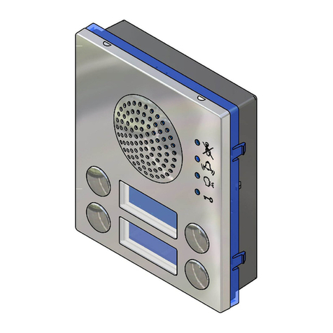
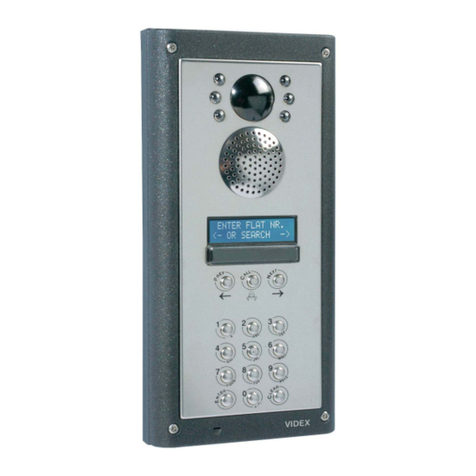
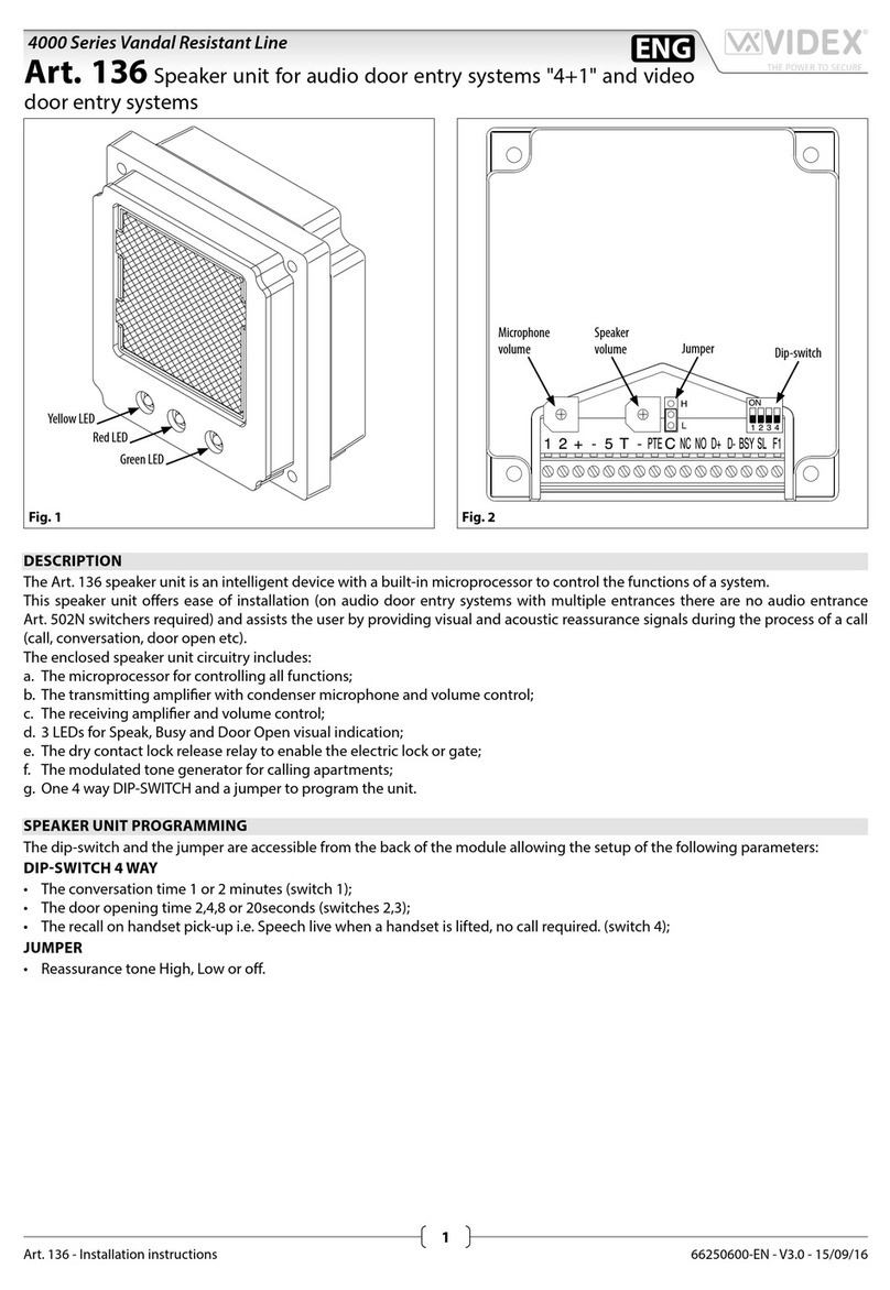
Videx 4534 User manual

66252030 - V 1.5 - 31/05/23
- 1 -
4000 Series
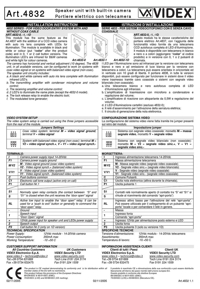
Art.4534 - 4534X - Installation instructions
D
C
E
A
BB
Fig. 1 Front
4534X
EXPANSION BUTTONS
PROG.
RS-485
RJ45
OPEN
CLOSE
GND
B
A
NO1
NC1
C1
RELAY 1 RELAY 2 WIEGAND INPUTS
POWER
NO2
GNDI
GND
+12
IN2
IN1
NC2
C2
D0
D1
LR
LG
Capacitor
discharge
Dry contact
output
Audio/video speaker unit
for IPure system
Made in Italy
M
G
F
H
I
L
N
Fig. 2 Back
The informations contained in this manual are valid
for devices with software version 1.4.0 and later.
AVAILABLE VERSIONS
Art.4534-0 Art.4534X-0
1
Art.4534-1
Art.4534X-1
1
2
Art.4534-2
Art.4534X-2
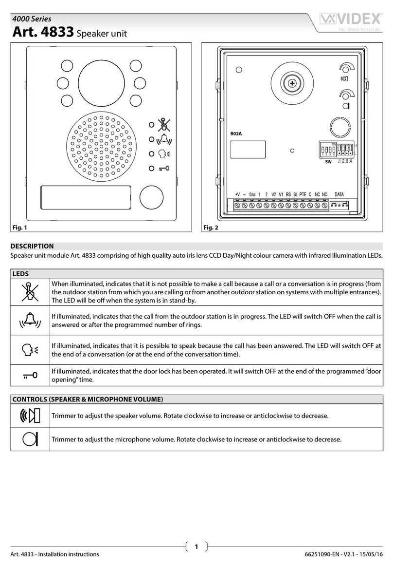
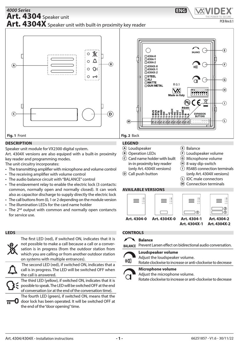
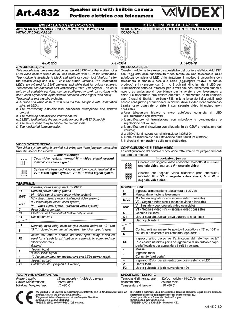
LEDS
Flashes when the called indoor station is busy.
The LED will be o when the system is in stand-by.
If illuminated, indicates that the call from the outdoor sta-
tion is in progress. The LED will switch OFF when the call is
answered or the call ends due to timeout.
If illuminated, indicates that it is possible to speak be-
cause the call has been answered. The LED will switch
OFF at the end of a conversation (or at the end of the
conversation time).
If illuminated, indicates that the door lock has been op-
erated. It will switch OFF at the end of the programmed
“door opening”time.
DESCRIPTION
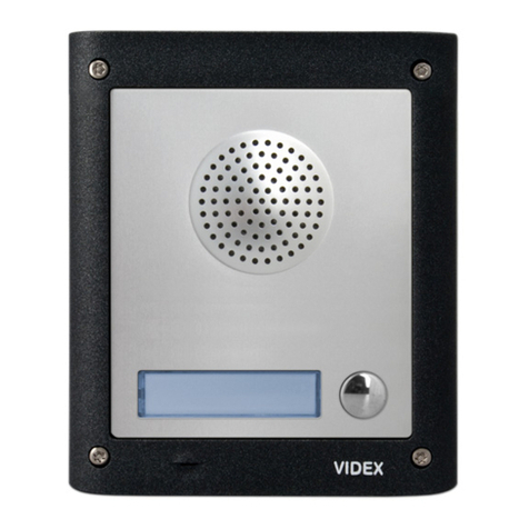
Speaker unit module for IPure system with built-in Wide Angle
colour camera with white light illumination LEDs. Depending
on the speaker unit version it can include zero, one or two call
push buttons.
Art.4534X versions are also equiped with a built-in proximity
key reader.
Hardware features:
• The transmitting amplier and microphone.
• The receiving amplier.
• Two relay outputs to enable electric lock and an additional
service (3 contacts each: common, normally open and nor-
mally closed).
• The call buttons from 0 to a maximum of 2 depending on the
module version.
• The illumination LEDs for the card name holder.
• The camera and illumination LEDs.
To download the programming software
Videx IPure Wizard and obtain the latest
rmware and manuals please visit the follow-
ing website and register
https://service.videx.it/
LEGEND
ACamera with illumination
LEDs
BOperation LEDs
CLoudspeaker
DCard name holder with
built-in proximity key
reader (only Art.4534X
versions)
ECall push button
FBoot loader push button
for rmware update
GPOE Ethernet interface
HRS485 termination switch
I
RS485 connection terminals
LButton expansion
modules connector
MDoor open relay operating
mode jumper
NConnection terminals
Art.4534X Speaker unit with built-in camera & proximity key reader for IPure system
Art.4534 Speaker unit with built-in camera for IPure system

66252030 - V 1.5 - 31/05/23
- 2 -
4000 Series
Art.4534 - 4534X - Installation instructions
Art.4534 Speaker unit with built-in camera for IPure system
Art.4534X Speaker unit with built-in camera & proximity key reader for IPure system
PROGRAMMING
RS485 BUS TERMINATION SWITCH
Open
Close
The programming of the module is car-
ried out through the Videx IPure Wizard
software but there are some adjustments
available directly on the module:
• RS-485 connection termination.
• Door open relay operating mode.
For the module programming refer to the
section Videx IPure Wizard.
DOOR OPEN RELAY OPERATING
MODE JUMPER
Capacitor discharge
Dry contact output
OPERATION
The system operation is supported by the built-in LED’s.
• When a visitor presses a call button the unit emits an intermit-
tent deep call tone and in correspondence with the tone the
red LED ashes (Fig. 3) until the resident answers or the
programmed call time expires.
• If the called indoor station is busy the red LED ashes (Fig. 4)
4 times quickly and the unit emits a deep tone on each ash.
• When the resident answers, the yellow LED (Fig. 5) illumi-
nates and remains illuminated until the conversation terminates.
• If the resident opens the door, the green LED illuminates
(Fig. 6) for the programmed door opening time.
ERROR MESSAGES
The LED is used also to provide error messages concerning
system malfunctions:
• A fast ashing LED shows connection to the push notication
service is being made. This should only be temporary; if this per-
sists then there is a connection issue to the service.
• Slow ashing means that the gateway cannot be reached (check gateway settings).
• xed on means that the SIP server cannot be reached or connection not allowed because of wrong credentials.
Fig. 3 Call in progress Fig. 4 Calling a busy indoor
station
Fig. 5 The conversation is in
progress
Fig. 6 Door opening
PROGRAMMING TAGS ONLY ART.4534X VERSIONS
The programming of the tags is carried out through the Videx IPure Wizard software.
USING TAGS
Place a tag in front of the tag reader:
↪If the tag is programmed, the external module emits two high-pitched “beeping” sounds and its relay is activated.
BIP BIP
↪If the tag is not programmed, the external module emits three low-pitched “beeping” sounds and its relay is not
activated.
BIP BIP BIP
ENABLE BOOTLOADER MODE
In case of rmware update failure (i.e. because of mains failure or cable disconnection during the
update etc.) and the door panel is no longer recognised by the Videx IPure Wizard software, you
can try to restore it by manually putting it into boot mode.
It is strongly recommended that this operation is carried out by a qualied engineer and in any
case after a discussion with Videx support.
• Disconnect the door panel from the power supply.
• Press and keep pressed the Fbutton (Fig. 2 on pag. 1) then connect again the power
supply source.
• The door panel will go into boot mode which is indicated by the four LED’s ashing alterna-
tively (Fig. 7).
• Now proceed using the utility “VidexFirmwareUpdater.exe” to upload the rmware to the device.
• If the update process terminates correctly, the device should be restored and ready to work.
• If the device still does not work, please contact the supplier to proceed according to the warranty terms.
Fig. 7 Door panel in BOOT-
LOADER mode
66252030 - V 1.5 - 31/05/23
- 3 -
4000 Series
Art.4534 - 4534X - Installation instructions
Art.4534 Speaker unit with built-in camera for IPure system
Art.4534X Speaker unit with built-in camera & proximity key reader for IPure system
HOW TO CONNECT AN ELECTRIC LOCK
The“door-open” relay can operate either as“capacitive discharge”or “dry contact” mode.
• In “capacitive discharge” operation mode the relay’s contacts, when active, supply directly the lock (12Vac/dc 1A max) for a
moment. You don’t need a power supply for the lock and the door opening time programmed do not aect the activation time.
• In “dry contact” operation mode the relay works in a traditional way, a power supply or a power source is needed to operate the
lock (12-24Vac/dc 2A max), and activation lasts according to the door opening time programmed.
* NOTE: in “capacitive discharge” modality (electric lock 12Vac/dc 1A max) the relay time cannot be more than 6 se-
conds because it could overhead the device.
A possibile deterioration of the mechanical performance of the electric lock, might cause the “capacitive discharge”to malfunction
in time. In case the electric lock is used in very dusty environments or in an abnormal climate condition, we suggest to use the“open
door”relay in“dry contacts”mode.
Fig. 8 Using capacitive discharge Fig. 9 Using separate P.S.U.
12V ac/dc
·12V AC/DC 1A Max
Using Capacitive Discharge
12V
230V
50/60 Hz
ART.321
230V
·12V AC 1.6A Max using Art.321
·24V AC/DC 2A Max using other
power supplies
Videx Electronics S.p.A.
Via del Lavoro 1, 63846 Monte Giberto (FM)
Phone: +39 0734 631669 - Fax +39 0734 631669
Autore:
Data modifica:
Data creazione:Title:
Notes:
Titolo:
Note: Cod.File:
Foglio
/ 11
Lorenzo Silla
4534-g001.dwg
07/02/2023
14/02/2023
.
4534 collegamento serratura elettrica
4534 electric lock connections
.
12V ac
Serratura Elettrica
Electric Lock
Serratura Elettrica
Electric Lock
Using separate P.S.U
NO1
NC1
C1
NO2
NC2
C2
D0
D1
LR
LG
GNDI
IN2
IN1
GND
+12V
GND
B
A
Close
Open
RS-485 Termination
Prog.
RJ45
Relay 1 Relay 2 Wiegand Inputs Power
Capacitor
Discharge
Dry Contact
Output
JP1: Door open relay operating mode jumper
Art.4534X IP: xxx.xxx.xxx.xxx
NO1
NC1
C1
NO2
NC2
C2
D0
D1
LR
LG
GNDI
IN2
IN1
GND
+12V
GND
B
A
Close
Open
RS-485 Termination
Prog.
RJ45
Relay 1 Relay 2 Wiegand Inputs Power
Capacitor
Discharge
Dry Contact
Output
JP1: Door open relay operating mode jumper
Art.4534X IP: xxx.xxx.xxx.xxx
12V ac/dc
·
12V AC/DC 1A Max
Using Capacitive Discharge
12V
230V
50/60 Hz
ART.321
230V
·12V AC 1.6A Max using Art.321
·24V AC/DC 2A Max using other
power supplies
Videx Electronics S.p.A.
Via del Lavoro 1, 63846 Monte Giberto (FM)
Phone: +39 0734 631669 - Fax +39 0734 631669
Autore:
Data modifica:
Data creazione:Title:
Notes:
Titolo:
Note: Cod.File:
Foglio
/ 11
Lorenzo Silla
4534-g001.dwg
07/02/2023
14/02/2023
.
4534 collegamento serratura elettrica
4534 electric lock connections
.
12V ac
Serratura Elettrica
Electric Lock
Serratura Elettrica
Electric Lock
Using separate P.S.U
NO1
NC1
C1
NO2
NC2
C2
D0
D1
LR
LG
GNDI
IN2
IN1
GND
+12V
GND
B
A
Close
Open
RS-485 Termination
Prog.
RJ45
Relay 1 Relay 2 Wiegand Inputs Power
Capacitor
Discharge
Dry Contact
Output
JP1: Door open relay operating mode jumper
Art.4534X IP: xxx.xxx.xxx.xxx
NO1
NC1
C1
NO2
NC2
C2
D0
D1
LR
LG
GNDI
IN2
IN1
GND
+12V
GND
B
A
Close
Open
RS-485 Termination
Prog.
RJ45
Relay 1 Relay 2 Wiegand Inputs Power
Capacitor
Discharge
Dry Contact
Output
JP1: Door open relay operating mode jumper
Art.4534X IP: xxx.xxx.xxx.xxx
12Vac 1.6A Max using Art.321
24Vac/dc 2A Max using other power supplies
12Vca/cc 1A Max
Apply the Yseal as shown in Fig. 10.
FITTING THE ANTITAMPER LOCKS
Fit the anti-tampering locks Was shown in Fig. 11.
Y
G
W
Fig. 10 Fig. 11
ADHESIVE GASKET PLACEMENT
• To avoid damage to the module front plate, mask the side that
will be in contact with the screwdriver blade;
• Insert the screwdriver (at side) into the card-holder hole as
shown in Fig. 12.
• Move the screwdriver to the left as shown in Fig. 13 to extract
the card name holder.
• Edit the card name then replace it inside the holder and ret:
insert the holder inside its housing from the left or right side
then push the other side until it clips into place.
HOW TO REMOVE/INSERT THE CARD NAME HOLDER
Fig. 12 Fig. 13

66252030 - V 1.5 - 31/05/23
- 4 -
4000 Series
Art.4534 - 4534X - Installation instructions
CAMERA NOTES
PRECAUTIONS ON THE CAMERA
• Please note that OPENING THE MODULE WILL INVALIDATE THE WARRANTY. In addition, any dust ingress could
COMPROMISE THE IMAGE QUALITY.
• REMOVE THE PROTECTIVE FILM ONLY AFTER INSTALLATION AND SUCCESSFUL TESTING HAS TAKEN PLACE to avoid
scratches that could AFFECT THE IMAGE QUALITY.
MAXIMUM ILLUMINATION DISTANCE
FROM CAMERA AT NIGHT
The illumination LED’s within the camera
will illuminate the visitor when they are
within 50cm of the camera.
MAX 50 cm
FIELDS OF VIEW
The elds of view for standard camera is 55° for vertical angle and 115° for horizontal
angle while for Wide Angle camera is 80° for vertical angle and 170° for horizontal angle
.
195 cm
80° 55°
170 cm
100 cm
75 cm
135 cm
70 cm
Vertical
angle
170°
115°
180 cm
105 cm
70 cm
Horizontal angle
Standard camera Wide Angle camera
CONNECTION TERMINAL SIGNALS
RELAY 1
NO1 Relay 1 normally open contact
NOTE:
12-24Vac/dc 2A
max
NC1 Relay 1 normally closed contact
C1 Relay 1 common contact
RELAY 2
NO2 Relay 2 normally open contact
NC2 Relay 2 normally closed contact
C2 Relay 2 common contact
WIEGAND
D0 Data 0 output
D1 Data 1 output
LR Red denied LED status input
LG Green accept LED status input
INPUTS
GNDI Ground for IN1 and IN2 inputs
IN2 Active low input 2 (when enabled activates the
programmed output)
IN1 Active low input 1 (when enabled activates the
programmed output)
POWER
GND 12Vdc - 400mA power supply input
+12V
RS485
GND RS-485 Connection
(termination adjusted through the switch G)
B
A
NOTE:
In case of capacitive discharge (see “How to connect an
electric lock” on page 3): Max 12Vac/dc 1A
TECHNICAL SPECIFICATION
Video codec: H.263
H.263+
H.264
Supported resolutions: 1280x720
640x480
352x288 (CIF)
320x240
Audio codec: G.711 μ-law
A-law
Sampling frequency: 8 khz
SIP compatibility: SIP 2.0
Power supply: 12Vdc - 400mA or
PoE 802.3af (Class 0 - 12.95W)
Power consumption: Stand by: 250mA
Operating: 380mA
Working temperature: -20 +60 °C
CLEANING OF THE PLATE
Use a clean and soft cloth. Use moderate warm water or non-ag-
gressive cleansers.
Do not use:
• abrasive liquids
• chlorine-based liquids
• metal cleaning products
• antioxidant products
Art.4534 Speaker unit with built-in camera for IPure system
Art.4534X Speaker unit with built-in camera & proximity key reader for IPure system

66252030 - V 1.5 - 31/05/23
- 5 -
4000 Series
Art.4534 - 4534X - Installation instructions
INTERNAL WEB SERVER
The device has an internal web server accessible via browser that allows you to change a part of the device settings without IPure
Wizard software.
ENABLE/DISABLE WEB SERVER
To enable or disable the web server, tick or untick the Enable HTTP
Server checkbox in the HTTP section of the IPure Wizard software.
If you want to restrict the access to the web server enable
Authentication by ticking the correspondent checkbox.
Once enabled, the default username is“admin”and defau-
lt password is“password”.
Fig. 14 Enable Authentication from IPure Wizard software
Fig. 15 Web server login
FIRST ACCESS
1.Open a browser and enter the complete IP address of the
device in the address bar:
I.E: http://192.168.2.187
2.Insert the default credentials (if you previously enabled Au-
thentication on the IPure Wizard software):
Username: admin
Password: password
3.Click/tap Login
NOTE:
• To nd the device IP address use the IPure Wizard software.
• httpsprotocol is not supported.
The followings options are available in the top menu bar:
HOME Shows basic device information
GENERAL Set video quality, audio levels, noise atte-
nuation and voice annunciation
APARTMENTS Manage at numbers, descriptions and
SIP numbers to call
ACCESS CONTROL Manage users and access control
Users Create, edit and delete a user
Access code Create, edit and delete an access code
RFID keys Create, edit and delete RFID key
Wiegand Edit wiegand settings
SIP SETTINGS Edit voip client settings
RTSP/HTTP Edit RTSP and HTTP server settings
LOGOUT Logout from web server
LANGUAGE Choose between English or Italian lan-
guages
Fig. 16 Home
Art.4534 Speaker unit with built-in camera for IPure system
Art.4534X Speaker unit with built-in camera & proximity key reader for IPure system

66252030 - V 1.5 - 31/05/23
- 6 -
4000 Series
Art.4534 - 4534X - Installation instructions
HOME
Shows the following device information:
• ID
• IP address
• MAC address
• Description
• Type
• Firmware version
Fig. 17 General
GENERAL
Enables you to make the following adjustments:
Video quality
Allows you to adjust video quality.
For every kind of connection you can select from 5 levels.
Note that a higher quality requires a higher bandwidth.
We suggest:
Videx monitors Very high
LAN VoIP Client Medium
To WAN VoIP Client Low
Levels
Allows you to adjust:
Reassurance Tone 3 levels
Its the reassurance tone emitted
during a call that conrms the call in
progress
Microphone 3 levels
Loudspeaker 3 levels
Other
Allows you to enable or disable the Noise Attenuation.
It is useful for those outdoor environments that are particularly loud.
Voice annunciation
Allows you to enable or disable Voice Annunciation.
The loudspeaker, during operation, will emit voice messages
during the progress of a call.
You can also choose the language and type of message for re-
lays 1 and 2.
Keep alive settings
This section species in which way the device checks the
network connection.
We suggest to avoid editing these settings unless you
have a specic requirement.
Click Save changes at the end to save the settings.
Art.4534 Speaker unit with built-in camera for IPure system
Art.4534X Speaker unit with built-in camera & proximity key reader for IPure system

66252030 - V 1.5 - 31/05/23
- 7 -
4000 Series
Art.4534 - 4534X - Installation instructions
APARTMENTS
This section show the list of apartments in the sy-
stem. In addition you can add a new one or edit.
For each apartment the following information is
shown:
Name Its the name of the apartment
(I.e. “BUTTON INT.1”, “BUTTON INT.2”
etc.)
SIP device
to call
Shows the extension number or the IP
of the SIP device which will be called
Fig. 18 Apartments
Fig. 19 Edit Apartments
Edit or delete an existing apartment
1.Click the button of the corresponding apartment you want
to edit.
2.In the pop-up window that appears, edit the elds you want
and click Save changes to save or Close to close wi-
thout saving the changes.
3.From the Apartment list, click the button of the correspon-
ding apartment you want to delete the SIP number to call.
Reset table
Click the Reset Table button to delete all the apartments.
Export apartment list as PDF
To export apartment list as a PDF le, click the button.
Art.4534 Speaker unit with built-in camera for IPure system
Art.4534X Speaker unit with built-in camera & proximity key reader for IPure system

66252030 - V 1.5 - 31/05/23
- 8 -
4000 Series
Art.4534 - 4534X - Installation instructions
ACCESS CONTROL
This section allows you to create users and asso-
ciate them access codes and RFID keys to use with
access control modules and outdoor stations.
Create a new user
1.On the User tab, click the Add new button:
a pop-up window will appear.
2.Fill the User Name and Enabled elds.
3.Click Save changes to save or Close to
close without saving the changes.
Edit or delete an existing user
1.Click the button of the corresponding user
you want to edit.
2.In the pop-up window that appears, edit the
elds you want and click Save changes to
save or Close to close without saving the
changes.
3.From the Users list, click the button of the corresponding apartment you want to delete.
Autoll From Apt
Click the Autoll From Apt button if you want to automatically ll the users list with all apartments..
Empty Table
Click the Empty Table button and then conrm if you want to delete all the users.
Fig. 20 Users
Assign an access code to a user
1.On the Access Codes tab, click the Add new button: a
pop-up window will appear.
2.On the Select User menu, select one of the users previously
created to assign an acces code.
3.On the Access Code eld, enter a 4 or 6 digit code:
i.e. 9876 or 123456.
4.On the Select Action menu, select the output you want to
activate with the code: i.e. Open door relay etc.
5.On the Select Enabled menu, chose Yes to enable the code.
6.On the Enable Readers check boxes, check all the access
control modules present in the system that you want to
enable for that user with that code.
7.Click Save changes to save or Close to close without
saving the changes.
Edit or delete an existing access code
1.Click the button of the corresponding access code you
want to edit.
2.In the pop-up window that appears, edit the elds you want
and click Save changes to save or Close to close wi-
thout saving the changes.
3.From the Access code list, click the button of the correspon-
ding access code you want to delete.
Art.4903
Fig. 21 Edit access code
Art.4534 Speaker unit with built-in camera for IPure system
Art.4534X Speaker unit with built-in camera & proximity key reader for IPure system

66252030 - V 1.5 - 31/05/23
- 9 -
4000 Series
Art.4534 - 4534X - Installation instructions
Assign an RFID key to an user
1.On the RFID Keys tab, click the Add new button: a pop-
up window will appear.
2.On the Select User menu, select one of the users previously
created that you want to assign a tag.
3.On the Site Code eld, enter the rst 3 digits of the tag code.
4.On the User Code eld, enter the last 5 digits of the tag code.
5.On the Select Action menu, select the output you want to
activate with the key: i.e. Open door relay etc.
6.On the Select Enabled menu, choose Yes to enable the key.
7.On the Enable Readers check boxes, check all the access
control modules present in the system that you want to
enable for that user with that key.
8.Click Save changes to save or Close to close without
saving the changes.
Edit or delete an existing RFID key
1.Click the button of the corresponding RFID key you want
to edit.
2.In the pop-up window that appears, edit the elds you want
and click Save changes to save or Close to close wi-
thout saving the changes.
3.From the RFID key list, click the button of the correspon-
ding RFID key you want to delete.
Art.4534X Art.4850R
016 , 40089
Fig. 22 Edit RFID key
Note about access control modules
• The maximum number of access control module including digital codelocks Art.4903 and RFID readers Art.4850R allowed is 8.
• First check box (0) is always the Art.4534X embedded RFID reader.
• Check boxes from 1to 8are Art.4903 or 4850R modules (if present in the system).
Export lists as PDF
To export any of Users, Access Codes or RFID Keys lists as a PDF le, click the corresponding sections button.
Art.4534 Speaker unit with built-in camera for IPure system
Art.4534X Speaker unit with built-in camera & proximity key reader for IPure system

66252030 - V 1.5 - 31/05/23
- 10 -
4000 Series
Art.4534 - 4534X - Installation instructions
Videx Electronics S.p.A.
Via del Lavoro 1, 63846 Monte Giberto (FM)
Phone: +39 0734 631669 - Fax +39 0734 631669
Autore:
Data modifica:
Data creazione:Title:
Notes:
Titolo:
Note: Cod.File:
Foglio
/ 11
Lorenzo Silla
4534-001.dwg
13/02/2023
13/02/2023
.
.
NO1
NC1
C1
NO2
NC2
C2
D0
D1
LR
LG
GNDI
IN2
IN1
GND
+12V
GND
B
A
Close
Open
RS-485 Termination
Prog.
RJ45
Relay 1 Relay 2 Wiegand Inputs Power
Capacitor
Discharge
Dry Contact
Output
JP1: Door open relay operating mode jumper
Art.4534X-1 IP: xxx.xxx.xxx.xxx
C
NO
NC
PTE
12/24
Vac/dc
A
B
GND
A
B
-
+
Close Open
RS-485 Termination
TENS UNITS STORE DELETE
Art.4850/R
Art.
HDR-
15-12
+V
230V
-V
Art.
HDR-
15-12
+V
230V
-V
-
+
SW1
NO2
NC2
SW2
C2
NO1
NC1
C1
NO1
NO2
NC1
NC2
MOV
JPL
A
B
A
B
RS485
Back light adjustment
jumper
Close Open
RS-485 Termination
Art.4903
Fig. 23 Access control modules example connection
Enable or disable Wiegand (if present in the system)
1.On the Wiegand tab, tick the Enabled check box to enable Wiegand output: now all codes or RFID key entered on Art.4534X
are managed by external third party access control, all settings on Users, Access Codes and RFID Keys tabs are ignored.
2.Untick the Enabled check box to disable Wiegand output.
Art.4534 Speaker unit with built-in camera for IPure system
Art.4534X Speaker unit with built-in camera & proximity key reader for IPure system

66252030 - V 1.5 - 31/05/23
- 11 -
4000 Series
Art.4534 - 4534X - Installation instructions
SIP SETTINGS
This section allow you to enable, disable and congure the de-
vice to work with third party SIP servers.
Please refer to SIP server specication to set all required parame-
ters (Client Settings,Video Codec and Audio Codec sections).
The door panel can work at the same time with third party SIP
server and with Videx Cloudnected App. When a call starts, all
involved devices will ring according to cascade settings, the rst
device that answers will stop the call to others.
The DTMF section allows the setting of the transmission mode
for the DTMF tones and the DTMF to be used to trig Relay 1,
Relay 2 and to switch Camera.
Click Save changes at the end to save the settings.
Fig. 24 SIP settings
RTSP/HTTP
This section allow you to enable, disable and congure the RTSP
server and the HTTP server.
The Real Time Streaming Protocol (RTSP) is a network control
protocol designed for use in entertainment and communica-
tions systems, and allows to interface the door panel video stre-
aming with external devices that are RTSP compliant.
Once the RTSP server is enabled (normally, default settings
don’t need to be changed but in case contact your system admi-
nistrator for details), the video streaming will be available at the
url shown next to the label Stream Url. The streaming is always
available independently from the call.
The HTTP server allows the control of the built-in relays through
http commands.
Once it is enabled as shown in the picture: if you open the link
http://192.168.2.187/RELAY/1/TRIG, you can trigger relay 1 of
the door panel.
In addition to the triggering options, there are also links avai-
lable to check the status of the two outputs and also the sta-
tus of the two inputs (i.e. applications where there is a need to
check the status of a gate or a door etc.)
Please note, while the required parameters are not entered, the
Save changes button is disabled.
Click Save changes at the end to save the settings.
Fig. 25 RTSP/HTTP settings
Art.4534 Speaker unit with built-in camera for IPure system
Art.4534X Speaker unit with built-in camera & proximity key reader for IPure system

66252030 - V 1.5 - 31/05/23
- 12 -
4000 Series
Art.4534 - 4534X - Installation instructions
OUTPUTS AND INPUTS
You can activate the two outputs and check the inputs status
by adding /relays to the device IP address on the address bar
of the browser.
I.E: http://192.168.2.187/relays.html
Outputs
Click on the desidered output to activate it.
There are three dierent operating mode:
Latch O On If the output is OFF, click on it
to turn ON and viceversa
Timer O On The output will be active for
a set time
Ring
repeater O On The output will be active in
pulsed mode
To set the operating modes you must use the Videx IPure
Wizard software.
Inputs
Allows you to check when an
input is active or inactive.
Active
Inactive
Fig. 26 Outputs and inputs
Art.4534 Speaker unit with built-in camera for IPure system
Art.4534X Speaker unit with built-in camera & proximity key reader for IPure system

66252030 - V 1.5 - 31/05/23
- 13 -
Serie 4000
Art.4534X - Istruzioni di installazione
D
C
E
A
BB
Fig. 1 Fronte
4534X
EXPANSION BUTTONS
PROG.
RS-485
RJ45
OPEN
CLOSE
GND
B
A
NO1
NC1
C1
RELAY 1 RELAY 2 WIEGAND INPUTS
POWER
NO2
GNDI
GND
+12
IN2
IN1
NC2
C2
D0
D1
LR
LG
Capacitor
discharge
Dry contact
output
Audio/video speaker unit
for IPure system
Made in Italy
M
G
F
H
I
L
N
Fig. 2 Retro
VERSIONI DISPONIBILI
Art.4534X-0
1
Art.4534X-1
1
2
Art.4534X-2
LED
Lampeggia quando il posto interno chiamato è occupato.
Si spegne quando il sistema entra in stand-by.
Se acceso indica che è in corso una chiamata.
Si spegne alla risposta dell’utente chiamato o allo sca-
dere del tempo senza risposta.
Se acceso indica che è possibile parlare con l’utente chi-
amato. Si spegne a ne conversazione (o allo scadere
del tempo di conversazione).
Se acceso indica ce sta avvenendo l’apertura della porta.
Si spegne allo scadere del tempo di apertura porta.
DESCRIZIONE
Modulo portiere elettrico per sistema IPure equipaggiato con tele-
camera Wide Angle a colori e LED di illumniazione a luce bianca ed
un lettore di chiavi di prossimità integrato.
A seconda della versione il modulo è dotato di nessuno, uno o
due pulsanti di chiamata.
Il circuito include:
• L’amplicatore trasmittente con il microfono.
• L’amplicatore ricevente.
• Due relé di asservimento per abilitare serrature elettriche e
servizi addizionali (3 contatti: comune, normalmente aperto e
normalmente chiuso).
• Pulsanti di chiamata da 0 a massimo 2 a seconda della versio-
ne del modulo.
• LED di illuminazione per il porta-cartellino.
• Telecamera completa di LED di illuminazione.
Per scaricare il software di programmazione
Videx IPure Wizard ed ottenere gli ultimi ag-
giornameni di rmware e manuali è necessa-
rio registrarsi sul sito web
https://service.videx.it/
LEGENDA
ATelecamera e LED di illumi-
nazione
BLED di funzionamento
CAltoparlante
DPorta-cartellino con letto-
re di chiavi di prossimità
integrato
EPulsante di chiamata
FPulsante Bootloader per
aggiornaemnto rmware
GInterfaccia Ethernet POE
HSwitch terminazione RS485
IMorsetteria di connessione
RS485
LConnettore per moduli
d’espansione pulsantiera
MJumper modalità operati-
va relé apri-porta
NMorsetteria di connessione
Le informazioni contenute in questo manuale sono valide
per i dispositivi con software versione 1.4.0 e successive.
Art.4534X
Portiere elettrico con telecamera e lettore di prossimità incorporati per sistema IPure

66252030 - V 1.5 - 31/05/23
- 14 -
Serie 4000
Art.4534X - Istruzioni di installazione
Art.4534X Portiere elettrico con telecamera e lettore di prossimità incorporati per sistema IPure
PROGRAMMAZIONE
INTERRUTTORE TERMINAZIONE
BUS RS485
Aperto
Chiuso
La programmazione dell’untià avviene
attraverso il software Videx IPure Wizard.
Direttamente sull’unità sono consentite
le seguenti regolazioni:
• Terminazione connessione RS-485.
• Modalità operativa relé apri-porta.
Per la programmazione dell’unità vedi la
sezione Videx IPure Wizard.
JUMPER MODALITÀ OPERATIVA RELÈ
APRIPORTA
Scarica capacitiva
Uscita relè a contatto pulito
FUNZIONAMENTO
Il funzionamento del sistema è supportato dai LED incorporati.
• Quando un utente preme un pulsante di chiamata l’unità emette
un tono profondo intermittente e contemporaneamente il LED
rosso (Fig. 3) lampeggia no a quando l’utente chiamato
non risponde oppure no allo scadere tempo di chiamata pro-
grammato.
• Se il posto interno chiamato è occupato il LED rosso
(Fig. 4) lampeggia velocementoe 4 volte e l’unità emette un
tono profondo ad ogni lampeggio.
• Quando l’utente chiamato risponde, il LED giallo (Fig. 5)
si accende e rimane acceso no alla ne della conversazione.
• Se l’utente chiamato apre la porta, il LED verde (Fig. 6) si
accende per il tempo di apertura porta programmato.
MESSAGGI DI ERRORE
Il LED viene utilizzato anche per segnalare messaggi di er-
rore inerenti a malfunzionamenti del sistema:
• Un lampeggio veloce del ash indica che la connessione con
il servizio di notiche push è stata fatta. Questo lampeggio dovrebbe essere temporaneo; se invece persiste signica che c’è qual-
cosa che non sta lavorando correttamente.
• Un lampeggio lento signica che il gateway impostato non può essere raggiunto (controllare le impostazioni del gateway).
• Il LED acceso sso signica che il server SIP non può essere raggiunto o che la connessione non è stata accettata a causa di cre-
denziali errate.
Fig. 3 Chiamata in corso Fig. 4 Chiamata verso un
interno occupato
Fig. 5 Conversazione in corso Fig. 6 Apertura della porta
PROGRAMMAZIONE DEI TAG
La programmazione dei tag avviene attraverso il software
Videx IPure Wizard
.
UTILIZZO DEI TAG
Presentare un tag master davanti al lettore di tag:
↪Se il tag è programmato, il modulo emette due “bip” acuti e il relè viene attivato.
BIP BIP
↪Se il tag non è programmato, il modulo emette tre “bip” bassi e il relè non viene attivato.
BIP BIP BIP
ABILITARE LA MODALITÀ BOOTLOADER
Nel caso di aggiornamento del rmware non riuscito (ad esempio a causa di una caduta di tensio-
ne o a casusa dello scollegamento del cavo durente l’aggiornamento ecc.) e l’unità non viene più
riconosciuta dal software Videx IPureWizard, è possibile resettare l’unità manualmente abilitando
la modalità bootloader.
Si raccomanda caldamente di fare eseguire questa operazione da personale qualicato ed in
ogni caso dopo aver contattato il supporto Videx.
• Scollegare l’unità dall’alimentatore.
• Premere e tenere premuto il pulsante F(Fig. 1 a pag. 13) dopodichè ricollegare l’alimen-
tazione.
• L’unità entrerà nella modalità bootloader: i quattro LED lampeggiano alternativamente (Fig. 7).
• Procedere ora con l’utility “VidexFirmwareUpdater.exe”per caricare il rmware nell’unità.
• Se il processo di caricamento è andato a buon ne, l’unità dovrebbe essere stata resettata e pronta all’utilizzo.
• Se l’unità continua a non funzionare, si prega di contattare il fornitore per procedere secondo le condizioni di garanzia.
Fig. 7 Unità in modalità BOOT-
LOADER

66252030 - V 1.5 - 31/05/23
- 15 -
Serie 4000
Art.4534X - Istruzioni di installazione
Art.4534X Portiere elettrico con telecamera e lettore di prossimità incorporati per sistema IPure
COME COLLEGARE LA SERRATURA ELETTRICA
Il relè“apriporta”può funzionare a “scarica capacitiva”o in modalità a “contatto pulito”.
• In modalità operativa a“scarica capacitiva”, i contatti del relè, quando attivi, alimentano direttamente la serratura (12Vca/cc 1A max) per alcu-
ni istanti. Non è necessario un alimentatore per la serratura e il tempo programmato di apertura porta non inuisce sul tempo di attivazione.
• In modalità operativa a“contatto pulito”il relè funziona in modo tradizionale ed è necessario un alimentatore o una fonte di alimentazione
diversa per attivare la serratura (12-24Vca/cc 2A max) e la durata dell’attivazione dipende dal tempo programmato di apertura della porta.
* NOTA: nella modalità "scarica capacitva" (serratura elettrica 12Vac/dc 1A max) il tempo del relè non può essere più di
6 secondi per evitare un probabile sovraccarico del dispositivo.
Un possibile peggioramento della prestazione meccanica della serratura elettrica potrebbe causare nel tempo un malfunziona-
mento della “scarica capacitiva”. In caso di utilizzo della serratura elettrica in un ambiente estremamente polveroso o in condizioni
climatiche dicili, suggeriamo di utilizzare il relè“apri-porta”in modalità a “contatti puliti”.
Fig. 8 Utilizzo scarica capacitiva Fig. 9 Utilizzo alimentatore separato
12V ac/dc
·12V AC/DC 1A Max
Using Capacitive Discharge
12V
230V
50/60 Hz
ART.321
230V
·12V AC 1.6A Max using Art.321
·24V AC/DC 2A Max using other
power supplies
Videx Electronics S.p.A.
Via del Lavoro 1, 63846 Monte Giberto (FM)
Phone: +39 0734 631669 - Fax +39 0734 631669
Autore:
Data modifica:
Data creazione:Title:
Notes:
Titolo:
Note: Cod.File:
Foglio
/ 11
Lorenzo Silla
4534-g001.dwg
07/02/2023
14/02/2023
.
4534 collegamento serratura elettrica
4534 electric lock connections
.
12V ac
Serratura Elettrica
Electric Lock
Serratura Elettrica
Electric Lock
Using separate P.S.U
NO1
NC1
C1
NO2
NC2
C2
D0
D1
LR
LG
GNDI
IN2
IN1
GND
+12V
GND
B
A
Close
Open
RS-485 Termination
Prog.
RJ45
Relay 1 Relay 2 Wiegand Inputs Power
Capacitor
Discharge
Dry Contact
Output
JP1: Door open relay operating mode jumper
Art.4534X IP: xxx.xxx.xxx.xxx
NO1
NC1
C1
NO2
NC2
C2
D0
D1
LR
LG
GNDI
IN2
IN1
GND
+12V
GND
B
A
Close
Open
RS-485 Termination
Prog.
RJ45
Relay 1 Relay 2 Wiegand Inputs Power
Capacitor
Discharge
Dry Contact
Output
JP1: Door open relay operating mode jumper
Art.4534X IP: xxx.xxx.xxx.xxx
12V ac/dc
·
12V AC/DC 1A Max
Using Capacitive Discharge
12V
230V
50/60 Hz
ART.321
230V
·12V AC 1.6A Max using Art.321
·24V AC/DC 2A Max using other
power supplies
Videx Electronics S.p.A.
Via del Lavoro 1, 63846 Monte Giberto (FM)
Phone: +39 0734 631669 - Fax +39 0734 631669
Autore:
Data modifica:
Data creazione:Title:
Notes:
Titolo:
Note: Cod.File:
Foglio
/ 11
Lorenzo Silla
4534-g001.dwg
07/02/2023
14/02/2023
.
4534 collegamento serratura elettrica
4534 electric lock connections
.
12V ac
Serratura Elettrica
Electric Lock
Serratura Elettrica
Electric Lock
Using separate P.S.U
NO1
NC1
C1
NO2
NC2
C2
D0
D1
LR
LG
GNDI
IN2
IN1
GND
+12V
GND
B
A
Close
Open
RS-485 Termination
Prog.
RJ45
Relay 1 Relay 2 Wiegand Inputs Power
Capacitor
Discharge
Dry Contact
Output
JP1: Door open relay operating mode jumper
Art.4534X IP: xxx.xxx.xxx.xxx
NO1
NC1
C1
NO2
NC2
C2
D0
D1
LR
LG
GNDI
IN2
IN1
GND
+12V
GND
B
A
Close
Open
RS-485 Termination
Prog.
RJ45
Relay 1 Relay 2 Wiegand Inputs Power
Capacitor
Discharge
Dry Contact
Output
JP1: Door open relay operating mode jumper
Art.4534X IP: xxx.xxx.xxx.xxx
12Vca 1,6A Max utilizzando l’Art.321
24Vca/cc 2A Max utilizzando altri alimentatori
12Vca/cc 1A Max
Applicare la guarnizione adesiva Ycome mostrato in Fig. 10.
INSERIMENTO FERMI ANTIEFFRAZIONE
Inserire i fermi anti-erazione Wcome mostrato in Fig. 11.
Y
G
W
Fig. 10 Fig. 11
APPLICAZIONE GUARNIZIONE ADESIVA
• Per evitare ammaccature della placca frontale, proteggere il
lato che verrà in contatto con la lama del cacciavite utilizzan-
do una striscia di nastro isolante.
• Inserire il cacciavite (lato piatto della lama) nell’apposita fes-
sura del porta cartellino come mostrato in Fig. 12.
• Fare leva con il cacciavite come mostrato in Fig. 13 per rimuove-
re il porta-cartellino (fare attenzione a non ammaccare la placca).
• Modicare il cartellino e riporlo all’interno del porta-cartellino
quindi riposizionare lo stesso al suo posto inserendolo nel suo
alloggiamento dal lato destro o sinistro e premendo il lato ri-
masto libero no all’aggancio (compiendo un movimento contrario a quello fatto per estrarlo).
RIMOZIONE/INSERIMENTO DEL PORTACARTELLINO
Fig. 12 Fig. 13

66252030 - V 1.5 - 31/05/23
- 16 -
Serie 4000
Art.4534X - Istruzioni di installazione
NOTE TELECAMERA
PRECAUZIONI SULLA TELECAMERA
• Si ricorda che L’APERTURA DEL MODULO NE INVALIDA LA GARANZIA. Inoltre l'eventuale ingresso di polvere potrebbe
COMPROMETTERE LA QUALITÀ DELL’IMMAGINE.
• RIMUOVERE LA PELLICOLA PROTETTIVA SOLO AL TERMINE DELL’INSTALLAZIONE E DELL’AVVENUTO COLLAUDO CON
SUCCESSO per evitare gra che potrebbero COMPROMETTERE LA QUALITÀ DELL’IMMAGINE.
DISTANZA DI ILLUMINAZIONE
MASSIMA DALLA CAMERA DI NOTTE
I LED di illuminazione all’interno della
camera illuminano correttamente il
visitatore quando si trova a una distanza
massima di 50cm.
MAX 50 cm
CAMPI DI VISUALE
I campi di visuale per la telecamera standard sono 55° per l’angolo verticale e 115° per
l’angolo orizzontale mentre per la telecamera Wide Angle sono 80° per l’angolo verti-
cale e 170° per l’angolo orizzontale.
195 cm
80° 55°
170 cm
100 cm
75 cm
135 cm
70 cm
Angolo
verticale
170°
115°
180 cm
105 cm
70 cm
Angolo orizzontale
Telecamera standard Telecamera Wide Angle
SEGNALI MORSETTERIA DI CONNESSIONE
RELAY 1
NO1 Relé 1 contatto normalmente aperto
NOTA:
12-24Vac/dc
2A max
NC1 Relé 1 contatto normalmente chiuso
C1 Relé 1 contatto comune
RELAY 2
NO2 Relé 2 contatto normalmente aperto
NC2 Relé 2 contatto normalmente chiuso
C2 Relé 2 contatto comune
WIEGAND
D0 Uscita Data 0
D1 Uscita Data 1
LR Ingresso stato LED rosso negato
LG Ingresso stato LED verde consentito
INPUTS
GNDI Massa per ingressi IN1 e IN2
IN2 Ingresso attivo basso 2 (quando abilitato attiva l'u-
scita programmata)
IN1 Ingresso attivo basso 1 (quando abilitato attiva l'u-
scita programmata)
POWER
GND Ingresso alimentazione 12Vdc - 400mA
+12V
RS485
GND Connessione RS-485
(terminazione regolata attraverso lo switch G)
B
A
NOTA:
In caso di scarica capacitiva (vedi “Come collegare la serratura
elettrica”a pagina 15): Max 12Vac/dc 1A
SPECIFICHE TECNICHE
Codec video: H.263
H.263+
H.264
Risoluzioni supportate: 1280x720
640x480
352x288 (CIF)
320x240
Codec audio: G.711 μ-law
A-law
Frequenza di
campionamento:
8 khz
Compatibilità SIP: SIP 2.0
Tensione di lavoro: 12Vdc - 400mA oppure
PoE 802.3af (Class 0 - 12.95W)
Assorbimenti: Stand by: 250mA
In funzione: 380mA
Temperatura di lavoro: -20 +60 °C
PULIZIA DELLA PLACCA
Usare un panno morbido e pulito. Usare acqua tiepida o un de-
tergente non aggressivo.
Non usare:
• prodotti abrasivi
• prodotti contenenti cloro
• prodotti per la pulizia dei metalli
• prodotti antiossidanti
Art.4534X Portiere elettrico con telecamera e lettore di prossimità incorporati per sistema IPure

66252030 - V 1.5 - 31/05/23
- 17 -
Serie 4000
Art.4534X - Istruzioni di installazione
SERVER WEB INTERNO
Il dispositivo include un server web integrato accessibile via browser che consente di variare una parte delle impostazioni senza
ricorrere al software IPure Wizard.
ABILITARE/DISABILITARE IL SERVER WEB
Per abilitare o disabilitare il server web, spuntare o togliere la
spunta sulla casella Abilita Server HTTP nella sezione HTTP del
software IPure Wizard.
Se si desidera limitare l’accesso al server web, abilitare l’
Autenticazione spuntando la casella corrispondente.
Una volta abilitata, il nome utente predenito è“admin”e
la password predenita è “password”.
Fig. 14 Abilitare l’Autenticazione tramite software IPure Wizard
Fig. 15 Web server login
PRIMO ACCESSO
1.Avviare un browser ed inserire l’indirizzo IP completo del
dispositivo nella barra degli indirizzi:
Es.: http://192.168.2.187
2.Inserire le credenziali di default (se si è precedentemente abi-
litata l’Autenticazione tramite il software IPure Wizard):
Nome utente: admin
Password: password
3.Cliccare/fare tap su Login
NOTE:
• Per trovare l’indirizzo IP del dispositivo utilizzare il software
IPure Wizard
• Il protocollo httpsnon è supportato.
Nella barra dei menù sono disponibili le seguenti opzioni:
HOME Mostra le informazioni di base del dispositivo
GENERALI Imposta la qualità video, i livelli audio, at-
tenuazione del rumore e annunci vocali
APPARTAMENTI Gestisce gli appartamenti, le descrizioni
e numeri SIP da chiamare
CONTROLLO
ACCESSI
Gestisce utenti e controllo accessi
Utenti Crea, modica e cancella un utente
Codici di accesso Crea, modica e cancella un codice d’accesso
Chiavi RFID Crea, modica e cancella una chiave RFID
Wiegand Modica le impostazioni wiegand
IMPOSTAZIONI SIP Modica le impostazioni del client voip
RTSP/HTTP Modica le impostazioni del server RTSP
e HTTP
LOGOUT Eettua il logout
LINGUA Sceglie tra le lingue Inglese o Italiano
Fig. 16 Home
Art.4534X Portiere elettrico con telecamera e lettore di prossimità incorporati per sistema IPure

66252030 - V 1.5 - 31/05/23
- 18 -
Serie 4000
Art.4534X - Istruzioni di installazione
HOME
Mostra le seguenti informazioni del dispositivo:
• ID
• Indirizzo IP
• Indirizzo MAC
• Descrizione
• Tipo
• Versione Firmware
Fig. 17 Generali
GENERALI
Consente di eettuare le seguenti regolazioni:
Qualità video
Consente di regolare la qualità del video.
Per ogni tipo di connessione è possibile selezionare tra 5 livelli.
Si noti che una qualità superiore richiede una maggiore lar-
ghezza di banda.
Suggeriamo:
Videocitofoni Videx Molto alta
LAN VoIP Client Meda
To WAN VoIP Client Bassa
Livelli
Consente di regolare:
Tono di chiamata 3 livelli
È il tono emesso durante una chiamata
a conferma che la chiamata è in corso
Microfono 3 livelli
Altoparlante 3 livelli
Altro
Consente di abilitare o disabilitare l’Attenuazione del rumore.
Utile per quegli ambienti esterni particolarmente rumorosi.
Annunci vocali
Consente di abilitare o disabilitare gli Annunci vocali.
L’altoparlante, durante il funzionamento, emetterà messaggi
vocali relativi all’operazione eseguita.
È inoltre possibile scegliere lingua e tipo di messaggio per Relay
1 e 2.
Impostazioni Keep alive
Questa sezione specica in che modo il dispositivo controlla la
connessione di rete.
Sconsigliamo di modicare queste impostazioni a
meno che non si abbia un problema specico.
Cliccare Salva alla ne per salvare le impostazioni.
Art.4534X Portiere elettrico con telecamera e lettore di prossimità incorporati per sistema IPure

66252030 - V 1.5 - 31/05/23
- 19 -
Serie 4000
Art.4534X - Istruzioni di installazione
APPARTAMENTI
Questa sezione mostra la lista degli appartamenti
presenti nel sistema. In aggiunta è possibile crearne
uno nuovo e modicarlo.
Per ogni appartmantento vengono mostrate le se-
guenti informazioni:
Nome È il nome dell’appartamento
(Es. “BUTTON INT.1”, “BUTTON INT.2”
ecc.)
Dispositivo
SIP da
chiamare
Mostra il numero di estensione o
l’IP del dispositivo SIP eventual-
mente da chiamare
Fig. 18 Appartamenti
Fig. 19 Modica appartamenti
Modicare o cancellare un appartamento esistente
1.Cliccare il pulsante dell’appartamento corrispondente che
si vuole modicare.
2.Nella nestra pop-up che compare, modicare i campi desi-
derati e cliccare Salva per salvare oppure Chiudi
per chiudere senza salvare le modiche.
3.Dalla lista Appartamenti, cliccare il pulsante dell’apparta-
mento corrispondente del quale si vuole cancellare il numero
SIP da chiamare.
Resetta tabella
Cliccare il pulsante Resetta Tabella per cancellare tutti gli
appartamenti.
Esportare la lista appartamenti in PDF
Per esportare la lista appartamenti in PDF, cliccare il pul-
sante .
Art.4534X Portiere elettrico con telecamera e lettore di prossimità incorporati per sistema IPure

66252030 - V 1.5 - 31/05/23
- 20 -
Serie 4000
Art.4534X - Istruzioni di installazione
CONTROLLO ACCESSI
Questa sezione consente di creare utenti e di asso-
ciare ad essi codici d’accesso e chiavi RFID da utiliz-
zare con moduli di controllo accessi e posti esterni.
Creare un nuovo utente
1.Nel tab Utenti, cliccare il pulsante Nuovo :
apparirà una nestra pop-up.
2.Completare i campi Nome e Abilitato.
3. Cliccare
Salva
per salvareoppure
Chiudi
per chiudere senza salvare le modiche.
Modicare o cancellare un utente esistente
1.Cliccare il pulsante dell’utente corrisponden-
te che si vuole modicare.
2.Nella nestra pop-up che compare, modicare
i campi desiderati e cliccare Salva per
salvare oppure Chiudi per chiudere senza
salvare le modiche.
3.Dalla lista Utenti, cliccare il pulsante corrispondente all’utente che si vuole cancellare.
Riempi da Apt
Cliccare il pulsante Riempi da Apt se si desidera riempire automanticamente la lista utenti con la stessa lista degli appartamenti.
Elimina tutto
Cliccare il pulsante Elimina Tutto e successivamente confermare se si desidera eliminare tutti gli utenti.
Fig. 20 Utenti
Assegnare un codice d’accesso ad un utente
1.Nel tab Codici di Accesso, cliccare il pulsante Nuovo :
apparirà una nestra pop-up.
2.Nel menù Seleziona Utente, selezionare uno degli utenti
precedentemente creati al quale si desidera assegnare un
codice d’accesso.
3.Nel campo Codice di Accesso, inserire il codice desiderato
da 4 o 6 cifre: Es. 9876 o 123456.
4.Nel menù Seleziona Azione, selezionare l’uscita che si desi-
dera attivare con il codice: Es. Relè apertura porta ecc.
5.Nel menù Abilitato, selezionare Si per abilitare il codice.
6. Sulle caselle Lettori abilitati, spuntare tutti i moduli di controllo
accessi presenti nel sistema che si desidera attivare per l’utente
con quel codice.
7.Cliccare Salva per salvare oppure Chiudi per
chiudere senza salvare le modiche.
Modicare o cancellare un codice d’accesso esistente
1.Cliccare il pulsante del codice d’accesso corrispondente
che si vuole modicare.
2.Nella nestra pop-up che compare, modicare i campi desi-
derati e cliccare Salva per salvare oppure Chiudi
per chiudere senza salvare le modiche.
3.Dalla lista Codici di Accesso, cliccare il pulsante corrispon-
dente al codice d’accesso che si vuole cancellare.
Art.4903
Fig. 21 Modica codice d’accesso
Art.4534X Portiere elettrico con telecamera e lettore di prossimità incorporati per sistema IPure
This manual suits for next models
2
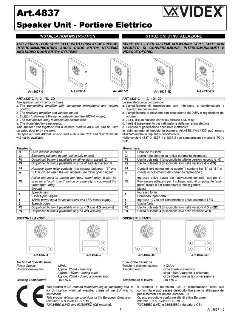
Table of contents
Languages:
Other Videx Speakers manuals

Videx
Videx 4838 Series User manual

Videx
Videx 4832 User manual

Videx
Videx 4000 Series User manual

Videx
Videx 4000 Series User manual

Videx
Videx 4837 Series User manual

Videx
Videx 4000 Series User manual

Videx
Videx 4000 Series User manual

Videx
Videx 4833 User manual

Videx
Videx 4000 Series User manual

Videx
Videx VX2200 User manual