Videx 4000 Series User manual

66252030 - V 1.1 - 31/03/22
- 1 -
4000 Series
Art.4534 - 4534X - Installation instructions
D
C
E
A
BB
Fig. 1 Front
4534X
EXPANSION BUTTONS
PROG.
RS-485
RJ45
OPEN
CLOSE
GND
B
A
NO1
NC1
C1
RELAY 1 RELAY 2 WIEGAND INPUTS
POWER
NO2
GNDI
GND
+12
IN2
IN1
NC2
C2
D0
D1
LR
LG
Capacitor
discharge
Dry contact
output
Audio/video speaker unit
for IPure system
Made in Italy
M
G
F
H
I
L
N
Fig. 2 Back
AVAILABLE VERSIONS
Art.4534-0 Art.4534X-0
1
Art.4534-1
Art.4534X-1
1
2
Art.4534-2
Art.4534X-2
LEDS
Flashes when the called indoor station is busy.
The LED will be o when the system is in stand-by.
If illuminated, indicates that the call from the outdoor sta-
tion is in progress. The LED will switch OFF when the call is
answered or the call ends due to timeout.
If illuminated, indicates that it is possible to speak be-
cause the call has been answered. The LED will switch
OFF at the end of a conversation (or at the end of the
conversation time).
If illuminated, indicates that the door lock has been op-
erated. It will switch OFF at the end of the programmed
“door opening” time.
DESCRIPTION
Speaker unit module for IP system with built-in Wide Angle co-
lour camera with white light illumination LEDs. Depending on
the speaker unit version it can include zero, one or two call push
buttons.
Art. 4534X versions are also equiped with a built-in proximity
key reader.
Hardware features:
• The transmitting amplier and microphone.
• The receiving amplier.
• Two relay outputs to enable electric lock and an additional
service (3 contacts each: common, normally open and nor-
mally closed).
• The call buttons from 0 to a maximum of 2 depending on the
module version.
• The illumination LEDs for the card name holder.
• The camera and illumination LEDs.
To download the programming software
VX IP Wizard and obtain the latest rmware
and manuals please visit the following web-
site and register
https://service.videx.it/
LEGEND
ACamera with illumination
LEDs
BOperation LEDs
CLoudspeaker
DCard name holder with
built-in proximity key
reader (only Art.4534X
versions)
ECall push button
FBoot loader push button
for rmware update
GPOE Ethernet interface
HRS485 termination switch
I
RS485 connection terminals
LButton expansion
modules connector
MDoor open relay operating
mode jumper
NConnection terminals
Art.4534X Speaker unit with built-in camera & proximity key reader for IPure system
Art.4534 Speaker unit with built-in camera for IPure system

66252030 - V 1.1 - 31/03/22
- 2 -
4000 Series
Art.4534 - 4534X - Installation instructions
Art.4534 Speaker unit with built-in camera for IPure syetem
Art.4534X Speaker unit with built-in camera & proximity key reader for IPure system
PROGRAMMING
RS485 BUS TERMINATION SWITCH
Open
Close
The programming of the module is car-
ried out through the VIDEX IP Wizard
software but there are some adjustments
available directly on the module:
• RS-485 connection termination.
• Door open relay operating mode.
For the module programming refer to the
section VIDEX IP Wizard.
DOOR OPEN RELAY OPERATING
MODE JUMPER
Capacitor discharge
Dry contact output
OPERATION
The system operation is supported by the built-in LED’s.
• When a visitor presses a call button the unit emits an intermit-
tent deep call tone and in correspondence with the tone the
red LED ashes (Fig. 3) until the resident answers or the
programmed call time expires.
• If the called indoor station is busy the red LED ashes (Fig. 4)
4 times quickly and the unit emits a deep tone on each ash.
• When the resident answers, the yellow LED (Fig. 5) illumi-
nates and remains illuminated until the conversation terminates.
• If the resident opens the door, the green LED illuminates
(Fig. 6) for the programmed door opening time.
ERROR MESSAGES
The LED is used also to provide error messages concerning
system malfunctions:
• A fast ashing LED shows connection to the push notication
service is being made. This should only be temporary; if this per-
sists then there is a connection issue to the service.
• Slow ashing means that the gateway cannot be reached (check gateway settings).
• xed on means that the SIP server cannot be reached or connection not allowed because of wrong credentials.
Fig. 3 Call in progress Fig. 4 Calling a busy indoor
station
Fig. 5 The conversation is in
progress
Fig. 6 Door opening
PROGRAMMING TAGS ONLY ART.4534X VERSIONS
The programming of the tags is carried out through the VIDEX IP Wizard software.
USING TAGS
Place a tag in front of the tag reader:
↪If the tag is programmed, the external module emits two high-pitched “beeping” sounds and its relay is activated.
BIP BIP
↪If the tag is not programmed, the external module emits three low-pitched “beeping” sounds and its relay is not
activated.
BIP BIP BIP
ENABLE BOOTLOADER MODE
In case of rmware update failure (i.e. because of mains failure or cable disconnection during the
update etc.) and the door panel is no longer recognised by the Videx IP Wizard software, you can
try to restore it by manually putting it into boot mode.
It is strongly recommended that this operation is carried out by a qualied engineer and in any
case after a discussion with Videx support.
• Disconnect the door panel from the power supply.
• Press and keep pressed the Fbutton (Fig. 2 on pag. 1) then connect again the power
supply source.
• The door panel will go into boot mode which is indicated by the four LED’s ashing alterna-
tively (Fig. 7).
• Now proceed using the utility “VidexFirmwareUpdater.exe” to upload the rmware to the device.
• If the update process terminates correctly, the device should be restored and ready to work.
• If the device still does not work, please contact the supplier to proceed according to the warranty terms.
Fig. 7 Door panel in BOOT-
LOADER mode

66252030 - V 1.1 - 31/03/22
- 3 -
4000 Series
Art.4534 - 4534X - Installation instructions
Art.4534 Speaker unit with built-in camera for IPure syetem
Art.4534X Speaker unit with built-in camera & proximity key reader for IPure system
CAMERA NOTES
PRECAUTIONS ON THE CAMERA
• Please note that OPENING THE MODULE WILL INVALIDATE THE WARRANTY. In addition, any dust ingress could
COMPROMISE THE IMAGE QUALITY.
• REMOVE THE PROTECTIVE FILM ONLY AFTER INSTALLATION AND SUCCESSFUL TESTING HAS TAKEN PLACE to avoid
scratches that could AFFECT THE IMAGE QUALITY.
MAXIMUM ILLUMINATION DISTANCE
FROM CAMERA AT NIGHT
The illumination LED’s within the camera
will illuminate the visitor when they are
within 50cm of the camera.
MAX 50 cm
FIELDS OF VIEW
The elds of view for standard camera is 55° for vertical angle and 115° for horizontal
angle while for Wide Angle camera is 80° for vertical angle and 170° for horizontal angle
.
195 cm
80° 55°
170 cm
100 cm
75 cm
135 cm
70 cm
Vertical
angle
170°
115°
180 cm
105 cm
70 cm
Horizontal angle
Standard camera Wide Angle camera
Apply the Yseal as shown in Fig. 8.
FITTING THE ANTITAMPER LOCKS
Fit the anti-tampering locks Was shown in Fig. 9.
Y
G
W
Fig. 8 Fig. 9
ADHESIVE GASKET PLACEMENT
• To avoid damage to the module front plate, mask the side that
will be in contact with the screwdriver blade;
• Insert the screwdriver (at side) into the card-holder hole as
shown in Fig. 10.
• Move the screwdriver to the left as shown in Fig. 11 to extract
the card name holder.
• Edit the card name then replace it inside the holder and ret:
insert the holder inside its housing from the left or right side
then push the other side until it clips into place.
HOW TO REMOVE/INSERT THE CARD NAME HOLDER
Fig. 10 Fig. 11

66252030 - V 1.1 - 31/03/22
- 4 -
4000 Series
Art.4534 - 4534X - Installation instructions
CONNECTION TERMINAL SIGNALS
RELAY 1
NO1 Relay 1 normally open contact
Max
12-24
Vac/dc
0.4A
NC1 Relay 1 normally closed contact
C1 Relay 1 common contact
RELAY 2
NO2 Relay 2 normally open contact
NC2 Relay 2 normally closed contact
C2 Relay 2 common contact
WIEGAND
D0 Data 0 output
D1 Data 1 output
LR Red denied LED status input
LG Green accept LED status input
INPUTS
GNDI Ground for IN1 and IN2 inputs
IN2 Active low input 2 (when enabled activates
the programmed output)
IN1 Active low input 1 (when enabled activates
the programmed output)
POWER GND 12Vdc - 400mA power supply input
+12V
RS485
GND RS-485 Connection
(termination adjusted through the switch G)
B
A
TECHNICAL SPECIFICATION
Video codec: H.263
H.263+
H.264
Supported resolutions: 1280x720
640x480
352x288 (CIF)
320x240
Audio codec: G.711 μ-law
A-law
Sampling frequency: 8 khz
SIP compatibility: SIP 2.0
Power supply: 12Vdc - 400mA
Power consumption: Stand by: 250mA
Operating: 380mA
Working temperature: -20 +60 °C
CLEANING OF THE PLATE
Use a clean and soft cloth. Use moderate warm water or non-ag-
gressive cleansers.
Do not use:
• abrasive liquids.
• chlorine-based liquids.
• metal cleaning products.
Art.4534 Speaker unit with built-in camera for IPure syetem
Art.4534X Speaker unit with built-in camera & proximity key reader for IPure system

66252030 - V 1.1 - 31/03/22
- 5 -
Serie 4000
Art.4534X - Istruzioni di installazione
D
C
E
A
BB
Fig. 1 Fronte
4534X
EXPANSION BUTTONS
PROG.
RS-485
RJ45
OPEN
CLOSE
GND
B
A
NO1
NC1
C1
RELAY 1 RELAY 2 WIEGAND INPUTS
POWER
NO2
GNDI
GND
+12
IN2
IN1
NC2
C2
D0
D1
LR
LG
Capacitor
discharge
Dry contact
output
Audio/video speaker unit
for IPure system
Made in Italy
M
G
F
H
I
L
N
Fig. 2 Retro
VERSIONI DISPONIBILI
Art.4534X-0
1
Art.4534X-1
1
2
Art.4534X-2
LED
Lampeggia quando il posto interno chiamato è occupato.
Si spegne quando il sistema entra in stand-by.
Se acceso indica che è in corso una chiamata.
Si spegne alla risposta dell’utente chiamato o allo sca-
dere del tempo senza risposta.
Se acceso indica che è possibile parlare con l’utente chi-
amato. Si spegne a ne conversazione (o allo scadere
del tempo di conversazione).
Se acceso indica ce sta avvenendo l’apertura della porta.
Si spegne allo scadere del tempo di apertura porta.
DESCRIZIONE
Modulo portiere elettrico per sistema IP equipaggiato con teleca-
meraWide Angle a colori e LED di illumniazione a luce bianca ed un
lettore di chiavi di prossimità integrato.
A seconda della versione il modulo è dotato di nessuno, uno o
due pulsanti di chiamata.
Il circuito include:
• L’amplicatore trasmittente con il microfono.
• L’amplicatore ricevente.
• Due relé di asservimento per abilitare serrature elettriche e
servizi addizionali (3 contatti: comune, normalmente aperto e
normalmente chiuso).
• Pulsanti di chiamata da 0 a massimo 2 a seconda della versio-
ne del modulo.
• LED di illuminazione per il porta-cartellino.
• Telecamera completa di LED di illuminazione.
Per scaricare il software di programmazione
VX IP Wizard ed ottenere gli ultimi aggiorna-
meni di rmware e manuali è necessario regi-
strarsi sul sito web
https://service.videx.it/
LEGENDA
ATelecamera e LED di illumi-
nazione
BLED di funzionamento
CAltoparlante
DPorta-cartellino con letto-
re di chiavi di prossimità
integrato
EPulsante di chiamata
FPulsante Bootloader per
aggiornaemnto rmware
GInterfaccia Ethernet POE
HSwitch terminazione RS485
IMorsetteria di connessione
RS485
LConnettore per moduli
d’espansione pulsantiera
MJumper modalità operati-
va relé apri-porta
NMorsetteria di connessione
Art.4534X
Portiere elettrico con telecamera e lettore di prossimità incorporati per sistema IPure

66252030 - V 1.1 - 31/03/22
- 6 -
Serie 4000
Art.4534X - Istruzioni di installazione
Art.4534X Portiere elettrico con telecamera e lettore di prossimità incorporati per sistema IPure
PROGRAMMAZIONE
INTERRUTTORE TERMINAZIONE
BUS RS485
Aperto
Chiuso
La programmazione dell’untià avviene
attraverso il software VIDEX IP Wizard. Di-
rettamente sull’unità sono consentite le
seguenti regolazioni:
• Terminazione connessione RS-485.
• Modalità operativa relé apri-porta.
Per la programmazione dell’unità vedi la
sezione VIDEX IP Wizard.
JUMPER MODALITÀ OPERATIVA RELÈ
APRIPORTA
Scarica capacitiva
Uscita relè a contatto pulito
FUNZIONAMENTO
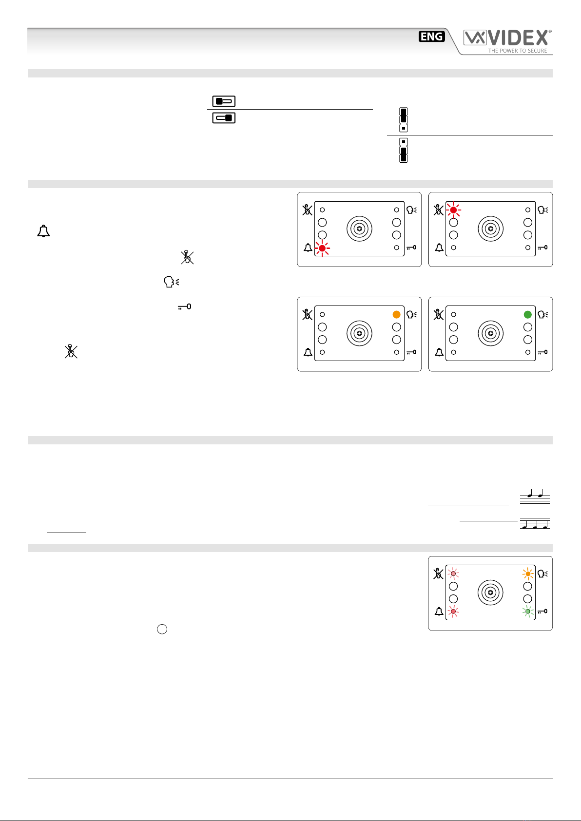
Il funzionamento del sistema è supportato dai LED incorporati.
• Quando un utente preme un pulsante di chiamata l’unità emette
un tono profondo intermittente e contemporaneamente il LED
rosso (Fig. 3) lampeggia no a quando l’utente chiamato
non risponde oppure no allo scadere tempo di chiamata pro-
grammato.
• Se il posto interno chiamato è occupato il LED rosso
(Fig. 4) lampeggia velocementoe 4 volte e l’unità emette un
tono profondo ad ogni lampeggio.
• Quando l’utente chiamato risponde, il LED giallo (Fig. 5)
si accende e rimane acceso no alla ne della conversazione.
• Se l’utente chiamato apre la porta, il LED verde (Fig. 6) si
accende per il tempo di apertura porta programmato.
MESSAGGI DI ERRORE
Il LED viene utilizzato anche per segnalare messaggi di er-
rore inerenti a malfunzionamenti del sistema:
• Un lampeggio veloce del ash indica che la connessione con
il servizio di notiche push è stata fatta. Questo lampeggio dovrebbe essere temporaneo; se invece persiste signica che c’è qual-
cosa che non sta lavorando correttamente.
• Un lampeggio lento signica che il gateway impostato non può essere raggiunto (controllare le impostazioni del gateway).
• Il LED acceso sso signica che il server SIP non può essere raggiunto o che la connessione non è stata accettata a causa di cre-
denziali errate.
Fig. 3 Chiamata in corso Fig. 4 Chiamata verso un
interno occupato
Fig. 5 Conversazione in corso Fig. 6 Apertura della porta
PROGRAMMAZIONE DEI TAG
La programmazione dei tag avviene attraverso il software VIDEX IP Wizard.
UTILIZZO DEI TAG
Presentare un tag master davanti al lettore di tag:
↪Se il tag è programmato, il modulo emette due “bip” acuti e il relè viene attivato.
BIP BIP
↪Se il tag non è programmato, il modulo emette tre “bip” bassi e il relè non viene attivato.
BIP BIP BIP
ABILITARE LA MODALITÀ BOOTLOADER
Nel caso di aggiornamento del rmware non riuscito (ad esempio a causa di una caduta di tensio-
ne o a casusa dello scollegamento del cavo durente l’aggiornamento ecc.) e l’unità non viene più
riconosciuta dal software Videx IP Wizard, è possibile resettare l’unità manualmente abilitando la
modalità bootloader.
Si raccomanda caldamente di fare eseguire questa operazione da personale qualicato ed in
ogni caso dopo aver contattato il supporto Videx.
• Scollegare l’unità dall’alimentatore.
• Premere e tenere premuto il pulsante F(Fig. 1 a pag. 5) dopodichè ricollegare l’alimen-
tazione.
• L’unità entrerà nella modalità bootloader: i quattro LED lampeggiano alternativamente (Fig. 7).
• Procedere ora con l’utility “VidexFirmwareUpdater.exe” per caricare il rmware nell’unità.
• Se il processo di caricamento è andato a buon ne, l’unità dovrebbe essere stata resettata e pronta all’utilizzo.
• Se l’unità continua a non funzionare, si prega di contattare il fornitore per procedere secondo le condizioni di garanzia.
Fig. 7 Unità in modalità BOOT-
LOADER

66252030 - V 1.1 - 31/03/22
- 7 -
Serie 4000
Art.4534X - Istruzioni di installazione
Art.4534X Portiere elettrico con telecamera e lettore di prossimità incorporati per sistema IPure
NOTE TELECAMERA
PRECAUZIONI SULLA TELECAMERA
• Si ricorda che L’APERTURA DEL MODULO NE INVALIDA LA GARANZIA. Inoltre l'eventuale ingresso di polvere potrebbe
COMPROMETTERE LA QUALITÀ DELL’IMMAGINE.
• RIMUOVERE LA PELLICOLA PROTETTIVA SOLO AL TERMINE DELL’INSTALLAZIONE E DELL’AVVENUTO COLLAUDO CON
SUCCESSO per evitare gra che potrebbero COMPROMETTERE LA QUALITÀ DELL’IMMAGINE.
DISTANZA DI ILLUMINAZIONE
MASSIMA DALLA CAMERA DI NOTTE
I LED di illuminazione all’interno della
camera illuminano correttamente il
visitatore quando si trova a una distanza
massima di 50cm.
MAX 50 cm
CAMPI DI VISUALE
I campi di visuale per la telecamera standard sono 55° per l’angolo verticale e 115° per
l’angolo orizzontale mentre per la telecamera Wide Angle sono 80° per l’angolo verti-
cale e 170° per l’angolo orizzontale.
195 cm
80° 55°
170 cm
100 cm
75 cm
135 cm
70 cm
Angolo
verticale
170°
115°
180 cm
105 cm
70 cm
Angolo orizzontale
Telecamera standard Telecamera Wide Angle
Applicare la guarnizione adesiva Ycome mostrato in Fig. 8.
INSERIMENTO FERMI ANTIEFFRAZIONE
Inserire i fermi anti-erazione Wcome mostrato in Fig. 9.
Y
G
W
Fig. 8 Fig. 9
APPLICAZIONE GUARNIZIONE ADESIVA
• Per evitare ammaccature della placca frontale, proteggere il
lato che verrà in contatto con la lama del cacciavite utilizzan-
do una striscia di nastro isolante.
• Inserire il cacciavite (lato piatto della lama) nell’apposita fes-
sura del porta cartellino come mostrato in Fig. 10.
• Fare leva con il cacciavite come mostrato in Fig. 11 per rimuove-
re il porta-cartellino (fare attenzione a non ammaccare la placca).
• Modicare il cartellino e riporlo all’interno del porta-cartellino
quindi riposizionare lo stesso al suo posto inserendolo nel suo
alloggiamento dal lato destro o sinistro e premendo il lato ri-
masto libero no all’aggancio (compiendo un movimento contrario a quello fatto per estrarlo).
RIMOZIONE/INSERIMENTO DEL PORTACARTELLINO
Fig. 10 Fig. 11

66252030 - V 1.1 - 31/03/22
- 8 -
Serie 4000
Art.4534X - Istruzioni di installazione
SEGNALI MORSETTERIA DI CONNESSIONE
RELAY 1
NO1
Relé 1 contatto normalmente aperto
Max
12-24
Vac/dc
0.4A
NC1
Relé 1 contatto normalmente chiuso
C1 Relé 1 contatto comune
RELAY 2
NO2
Relé 2 contatto normalmente aperto
NC2
Relé 2 contatto normalmente chiuso
C2 Relé 2contatto comune
WIEGAND
D0 Uscita Data 0
D1 Uscita Data 1
LR Ingresso stato LED rosso negato
LG Ingresso stato LED verde consentito
INPUTS
GNDI Massa per ingressi IN1 e IN2
IN2 Ingresso attivo basso 2 (quando abilitato
attiva l'uscita programmata)
IN1 Ingresso attivo basso 1 (quando abilitato
attiva l'uscita programmata)
POWER GND Ingresso alimentazione 12Vdc - 400mA
+12V
RS485
GND Connessione RS-485
(terminazione regolata attraverso lo swtich H)
B
A
SPECIFICHE TECNICHE
Codec video: H.263
H.263+
H.264
Risoluzioni
supportate:
1280x720
640x480
352x288 (CIF)
320x240
Codec audio: G.711 μ-law
A-law
Frequenza di
campionamento:
8 khz
Compatibilità SIP: SIP 2.0
Tensione di lavoro: 12Vdc - 400mA
Assorbimenti: Stand by: 250mA
In funzione: 380mA
Temperatura di lavoro: -20 +60 °C
PULIZIA DELLA PLACCA
Usare un panno morbido e pulito. Usare acqua tiepida o un de-
tergente non aggressivo.
Non usare:
• prodotti abrasivi.
• prodotti contenenti cloro.
• prodotti per la pulizia dei metalli.
Art.4534X Portiere elettrico con telecamera e lettore di prossimità incorporati per sistema IPure

66252030 - V 1.1 - 31/03/22
- 9 -
Switch PoE
Switch PoE
Switch PoE
22
2
2
2
2
2505
2505
Rif.SLD_IPURE_V_001

66252030 - V 1.1 - 31/03/22
- 10 -

66252030 - V 1.1 - 31/03/22
- 11 -
DISPOSAL
In accordance with the Legislative Decree no. 49 of 14 March 2014 “Implementation of the Directive 2012/19/EU on waste
electrical and electronic equipment (WEEE)”.
The crossed-out bin symbol on the equipment or on the packaging indicates that when the product reaches the end of
its lifetime, it must be collected separately from mixed municipal waste. The user must, therefore, dispose of the equip-
ment at the end of its lifetime in the suitable waste collection centres or bring it to the retailer during the purchase of a
new equipment of equivalent type at the ratio of one-to-one. Furthermore, the user is allowed to dispose of the WEEEs
of very small size (domestic appliances without any external dimension exceeding 25 cm (9.84 inches) for free to the
retailers, without any purchase obligation. The correct waste disposal of the WEEEs contributes to their reuse, recycling
and recovery and avoids potential negative eects on the environment and human health due to the possible presence
of dangerous substances within them.
SMALTIMENTO
Ai sensi del Decreto Legislativo 14 marzo 2014, n° 49 “Attuazione della direttiva 2012/19/UE sui riuti di apparecchiature
elettriche ed elettroniche (RAEE)”.
Il simbolo del cassonetto barrato riportato sull’apparecchiatura o sulla sua confezione indica che il prodotto alla ne della
propria vita utile deve essere raccolto separatamente dagli altri riuti urbani misti. L’utente dovrà, pertanto, conferire l’appa-
recchiatura giunta a ne vita presso gli idonei centri di raccolta dierenziata oppure riconsegnarla al rivenditore al momento
dell’acquisto di una nuova apparecchiatura di tipo equivalente, in ragione di uno a uno. L’utente ha, inoltre, la possibilità di
conferire gratuitamente presso i distributori, senza alcun obbligo di acquisto, per i RAEE di piccolissime dimensioni (per le
apparecchiature di tipo domestico con nessuna dimensione esterna superiore a 25 cm).
L’adeguata raccolta dierenziata dei RAEE contribuisce al loro riutilizzo, riciclaggio e recupero ed evita potenziali eetti nega-
tivi sull’ambiente e sulla salute umana dovuti alla eventuale presenza di sostanze pericolose al loro interno.
ÉLIMINATION
Conformément au décret législatif n ° 49 du 14 mars 2014 relatif à l’«Application de la directive 2012/19 / UE relative aux
déchets d’équipements électriques et électroniques (DEEE)».
Le symbole de la poubelle barrée sur l’équipement ou sur son emballage indique que le produit en n de vie utile doit être
collecté séparément des autres déchets municipaux en mélange. L’utilisateur doit donc remettre l’équipement en n de
vie aux centres de collecte appropriés ou le restituer au revendeur lors de l’achat d’un nouveau type d’équipement équi-
valent, dans le rapport de un à un. De plus, l’utilisateur a la possibilité de conférer gratuitement aux distributeurs, sans au-
cune obligation d’achat, de très petits DEEE (pour les appareils ménagers sans dimensions extérieures supérieures à 25 cm).
La collecte séparée adéquate des DEEE contribue à leur réutilisation, leur recyclage et leur valorisation et évite les éventuels
eets négatifs sur l’environnement et la santé humaine en raison de la présence possible de substances dangereuses dans
ceux-ci.
ELIMINACIÓN
De conformidad con el Decreto legislativo n. 49 de 14 de marzo 2014 “Aplicación de la Directiva 2012/19/UE relativa a resi-
duos de aparatos eléctricos y electrónicos (RAEE)”.
El símbolo del contenedor tachado indicado sobre los aparatos o sobre los embalajes señala que el producto al nal de su
vida útil debe ser recogido separadamente de otros residuos municipales mezclados. Por tanto, el usuario deberà conferir los
aparatos al nal de su vida útil en los apropriados centros de recogida selectiva o devolverlos al revendedor al momento de
la compra de nuevos aparatos equivalentes, en una relación de uno a uno. Además, el usuario tiene la posibilidad de entre-
gar sin cargo a los distribuidores, sin ninguna obligación de compra, los RAEEs muy pequeños (para electrodomésticos sin
dimensiones externas superiores a 25 cm).
La recogida selectiva apropriada de los RAEEs contribuye a su reutilización, reciclaje y valorización y evita potenciales impactos
negativos sobre el medio ambiente y la salud humana debidos a la possible presencia de substancias peligrosas dentro de ellos.
ELIMINAÇÃO
De acordo com o Decreto Legislativo n.º 49 de 14 de março de 2014“Implementação da Diretiva 2012/19/UE relativa
aos resíduos de equipamentos elétricos e eletrónicos (REEE)”.
O símbolo do caixote do lixo riscado no equipamento ou na embalagem indica que quando o produto atinge o fim
da sua vida útil, deve ser recolhido separadamente dos resíduos urbanos mistos. O utilizador deve, portanto, elimi-
nar o equipamento no final da sua vida útil nos centros de recolha de resíduos adequados ou levá-lo ao vendedor
durante a compra de um novo equipamento de tipo equivalente, na proporção de um para um. Além disso, o utili-
zador pode eliminar gratuitamente os REEE de dimensões muito reduzidas aos vendedores, sem qualquer obrigação
de compra.(só aparelhos domésticos sem qualquer dimensão externa que exceda 25 cm, ou seja 9,84 polegadas).
A correta eliminação dos REEE contribui para a sua reutilização, reciclagem e recuperação e evita potenciais efeitos
negativos sobre o ambiente e a saúde humana devido à possível presença de substâncias perigosas no seu interior.
VERWIJDERING
In overeenstemming met het Wetsbesluit nr. 49 van 14 maart 2015 “Implementatie van de Richtlijn 2012/19/EU
inzake afgedankte elektrische en elektronische apparaten (AEEA)”.
Het doorgekruiste vuilnisbaksymbool op het apparaat of de verpakking geeft aan dat het product aan het einde van
zijn levensduur niet samen met het gewone huisvuil weggegooid mag worden. De gebruiker moet het apparaat aan
het einde van zijn levensduur inleveren bij een gepast inzamelpunt of de winkel waar hij een nieuw apparaat van
een gelijksoortig type zal kopen. De gebruiker kan tevens AEEA’s van een zeer klein formaat (huishoudapparaten
met een buitenafmeting kleiner dan 25 cm (9,84 inch) gratis en zonder enige aankoopverplichting bij handelaars
inleveren. Een juiste verwijdering van AEEA’s draagt bij tot hergebruik, recycling en terugwinning, en voorkomt
potentiële negatieve effecten op het milieu en de menselijke gezondheid door de mogelijke aanwezigheid van
gevaarlijke stoffen.

MANUFACTURER
FABBRICANTE
FABRICANT
FABRICANTE
FABRIKANT
FABRICANTE
VIDEX ELECTRONICS S.P.A.
Via del Lavoro, 1
63846 Monte Giberto (FM) Italy
Tel (+39) 0734 631669
Fax (+39) 0734 632475
CUSTOMER SUPPORT
SUPPORTO CLIENTI
SUPPORTS CLIENTS
ATENCIÓN AL CLIENTE
KLANTENDIENST
APOIO AO CLIENTE
VIDEX ELECTRONICS S.P.A.
www.videx.it - technical@videx.it
Tel: +39 0734-631669
Fax: +39 0734-632475
UK Customers only:
VIDEX SECURITY LTD
www.videxuk.com
Tech Line: 0191 224 3174
Fax: 0191 224 1559
Main UK oce:
VIDEX SECURITY LTD
1 Osprey Trinity Park
Trinity Way
LONDON E4 8TD
Phone: (+44) 0370 300 1240
Fax: (+44) 020 8523 5825
www.videxuk.com
Northern UK oce:
VIDEX SECURITY LTD
Unit 4-7
Chillingham Industrial Estate
Chapman Street
NEWCASTLE UPON TYNE - NE6 2XX
Tech Line: (+44) 0191 224 3174
Phone: (+44) 0370 300 1240
Fax: (+44) 0191 224 1559
Greece oce:
VIDEX HELLAS Electronics
48 Filolaou Str.
11633 ATHENS
Phone: (+30) 210 7521028
(+30) 210 7521998
Fax: (+30) 210 7560712
www.videx.gr
Danish oce:
VIDEX DANMARK
Hammershusgade 15
DK-2100 COPENHAGEN
Phone: (+45) 39 29 80 00
Fax: (+45) 39 27 77 75
www.videx.dk
Benelux oce:
NESTOR COMPANY NV
E3 laan, 93
B-9800 Deinze
Phone: (+32) 9 380 40 20
Fax: (+32) 9 380 40 25
www.videx.be
Dutch oce:
NESTOR COMPANY BV
Business Center Twente (BCT)
Grotestraat, 64
NL-7622 GM Borne
www.videxintercom.nl
info@videxintercom.nl
The product is CE marked demonstrating its conformity and is for distribution with-
in all member states of the EU with no restrictions. This product follows the provi-
sions of the European Directives 2014/30/EU (EMC); 2014/35/EU (LVD); 2011/65/EU
(RoHS): CE marking 93/68/EEC.
Il prodotto è marchiato CE a dimostrazione della sua conformità e può essere distri-
buito liberamente all’interno dei paesi membri dell’Unione Europea UE.
Questo prodotto è conforme alle direttive Europee: 2014/30/UE (EMC); 2014/35/UE
(LVD); 2011/65/UE (RoHS): marcatura CE 93/68/EEC.
Le produit est marqué CE à preuve de sa conformité et peut être distribué librement
à l’intérieur des pays membres de l’union européenne EU.
Ce produit est conforme aux directives européennes 2014/30/EU (EMC) ; 2014/35/
EU (LVD) ; 2011/65/EU (RoHS): marquage CE 93/68/EEC.
El producto lleva la marca CE que demuestra su conformidad y puede ser distribuido
en todos los estados miembros de la unión europea UE.
Este producto cumple con las Directivas Europeas 2014/30/EU (EMC); 2014/35/EU
(LVD); 2011/65/EU (RoHS): marca CE 93/68/EEC.
Het product heeft de CE-markering om de conformiteit ervan aan te tonen en is be-
stemd voor distributie binnen de lidstaten van de EU zonder beperkingen. Dit pro-
duct volgt de bepalingen van de Europese Richtlijnen 2014/30/EU (EMC); 2014/35/
EU (LVD); 2011/65/EU (RoHS): CE-markering 93/68/EEG.
O produto tem a marca CE que demonstra a sua conformidade e destina-se a dis-
tribuição em todos os estados membros da UE, sem restrições. Este produto segue
as disposições das Diretivas Europeias 2014/30/UE (EMC); 2014/35/UE (LVD);
2011/65/UE (RoHS): marcação CE 93/68/CEE.
CE
(RoHS) EU// ;(EU (LVD// ;(EU (EMC//
EEC// CE
Other manuals for 4000 Series
31
This manual suits for next models
8
Table of contents
Languages:
Other Videx Speakers manuals

Videx
Videx 4000 Series User manual

Videx
Videx 4000 Series User manual

Videx
Videx 4837 Series User manual

Videx
Videx 136 User manual

Videx
Videx VX2200 User manual

Videx
Videx 4000 Series User manual

Videx
Videx 4000 Series User manual

Videx
Videx 4833 User manual

Videx
Videx 4000 Series User manual

Videx
Videx 4836 User manual