66250240 - V2.0 - 31/10/18
- 4 -
Serie 4000
Art.4838 - Istruzioni di installazione
AB
C
C
D
Fig. 1 Fronte
5
PTE
C
NC
NO
BSY
SL
F1
LB
T
CB
COM
P1
1
2
+12
GND
P2
P3
P4
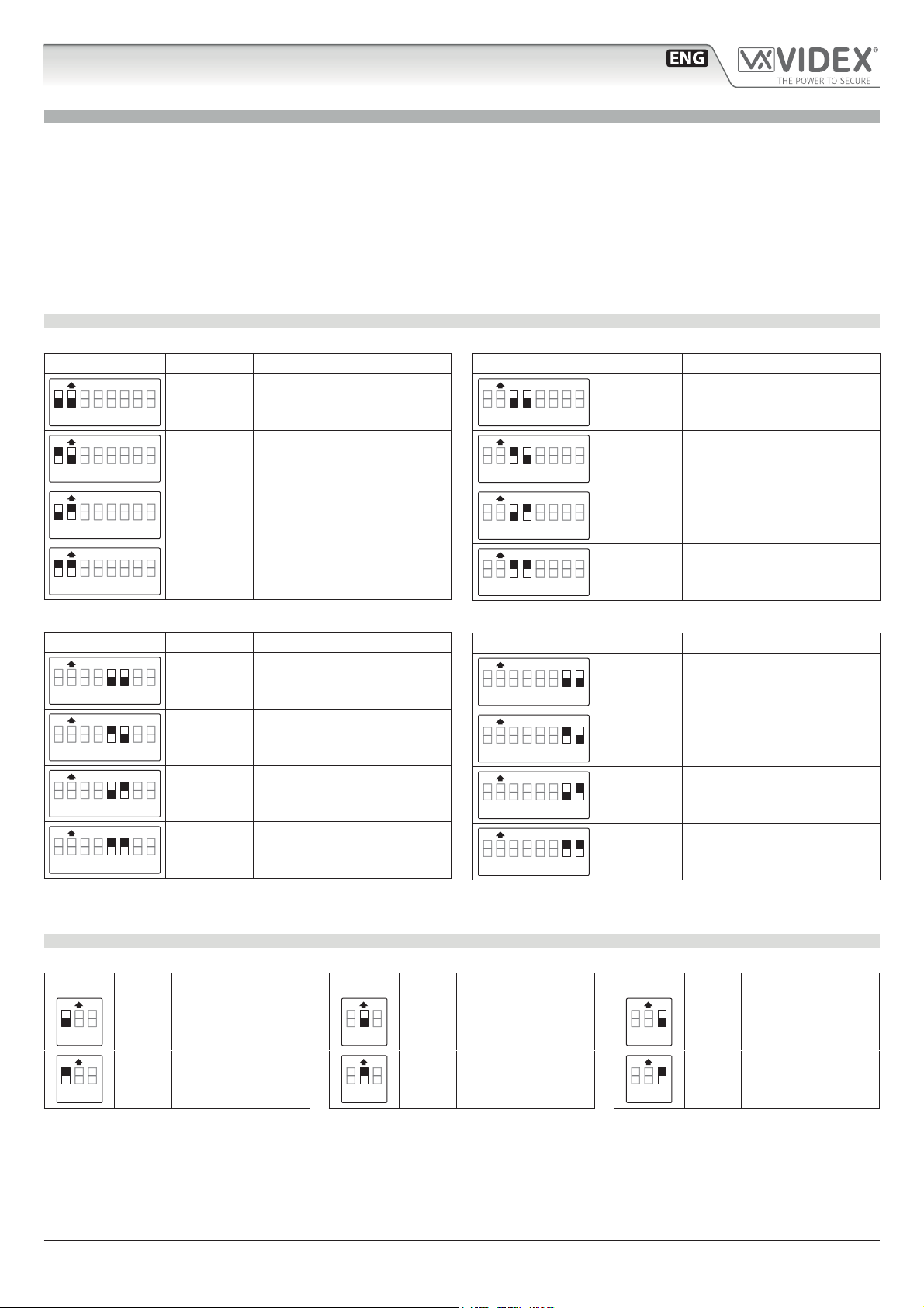
DIP-SWITCH 1 SETTINGS (8 way)
MELODIES
1,2 RINGS
3,4 SPEECH TIME
5,6 DOOR OP. TIME
7,8
SWITCHES
SETTINGS
OFF OFF
OFFON ONOFF
ON ON
MELODY 1
MELODY 2
MELODY 3
MELODY 4
2 RINGS
4 RINGS
6 RINGS
8 RINGS
30s
60s
90s
120s
1s
4s
8s
16s
DIP-SWITCH 2 SETTINGS (3 way)
STATUS FUNCTION
SWITCHES
OFF
ON
OFF
ON
Reassurance tone disabled
Reassurance tone enabled
"4+1" System (standard)
"5+1" System (privacy of speech)
OFF
ON
1
2
3
Made in Italy
DIP-SW 1 DIP-SW 2
Normal operation
Recall on handset pick up (only "4+1")
4838-0
4838-1
4838-2
4838-1D
4838-2D
Stainless Steel Matte
Aluminium
High Brass
E
F
HG
I
Fig. 2 Retro
DESCRIZIONE
I portieri della serie Art.4838 sono di tipo intelligente ed incorporano un micro-
processore per la gestione di tutte le funzioni. Oltre a consentire una facile in-
stallazione (nei sistemi citofonici multi-ingresso non richiedono lo scambiatore
d’ingressi Art.502N), questi portieri agevolano gli utenti del sistema fornendo
segnalazioni acustiche e visive in merito al funzionamento dell’impianto (chia-
mata, conversazione ecc.). L’elettronica del portiere elettrico comprende:
• Il microprocessore;
• L’amplicatore di trasmissione con microfono a condensatore e regolazio-
ne del volume;
• L’amplicatore di ricezione con altoparlante da 0,5W e regolazione del volume;
• 2 LED d’illuminazione cartellini (escluso Art.4838-0);
• 4 LED per le indicazioni visive in merito al funzionamento dell’impianto;
• Il relè d’asservimento per l’attivazione della serratura elettrica;
• Il circuito di generazione della nota elettronica;
• 2 dip-switch di programmazione a 3 e ad 8 vie.
Questo portiere, in abbinamento al modulo telecamera Art.4830, può es-
sere impiegato anche in sistemi videocitofonici: in tal caso, nei sistemi a più
ingressi, consente di sostituire gli scambiatori d’ingressi video Art.892 con
dei semplici relé Art.506N.
LEGENDA
AAltoparlante
BLED
CPulsanti di chiamata
DPorta cartellini
EVolume altoparlante
FVolume microfono
GDip-switch a 8 vie
HDip-switch a 3 vie
IMorsetteria di connessione
VERSIONI DISPONIBILI
Art.4838-0
1
Art.4838-1
1
2
Art.4838-2
13
Art.4838-1D
13
42
Art.4838-2D
LED
Il primo LED (rosso) indica, se acceso, che non è possi-
bile eettuare la chiamata perché è in corso una chia-
mata o una conversazione (dall’ingresso dal quale si
sta chiamando o da un altro ingresso in caso d’ingres-
si multipli). Chiusa la conversazione, il LED si spegne
segnalando che è possibile fare una nuova chiamata.
Il secondo LED (rosso) indica, se acceso, che è in corso una
chiamata. Il LED si spegne alla risposta dell’utente chiamato.
Il terzo LED (verde) indica, se acceso, che è possibile
parlare con l’utente chiamato. Il LED si spegne a ne
conversazione.
Il quarto LED (giallo) contrassegnato dal simbolo , se ac-
ceso, indica che sta avvenendo l’apertura della porta. Il
LED si spegne allo scadere del tempo di apertura porta.
REGOLAZIONI
Volume altoparlante
Regolazione del volume dell’altopalralte.
Ruotare in senso orario per aumentare o antiorario per diminuire
Volume microfono
Regolazione del volume del microfono.
Ruotare in senso orario per aumentare o antiorario per diminuire
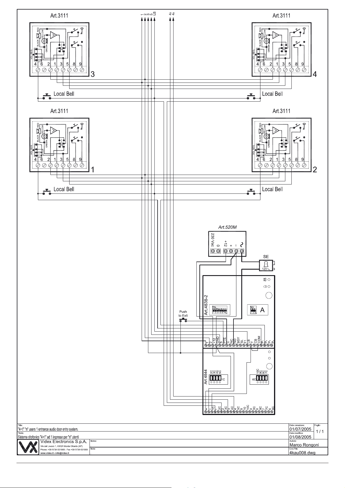
Art.4838 Portiere per sistemi citofonici “4+1”, “5+1” con segreto di
conversazione, intercomunicanti e video