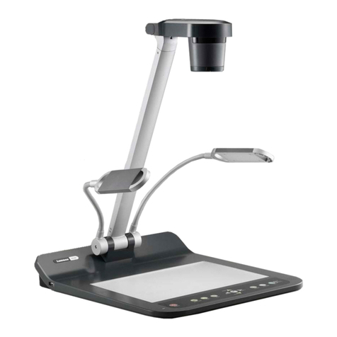
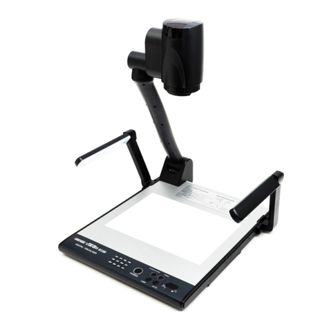
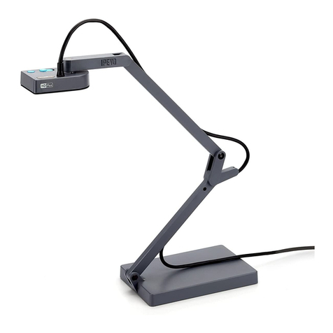
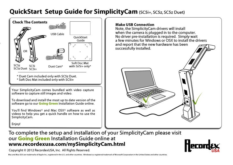
Vidifox PV 360 User manual

Vidifox
®
Document
Camera
PV
360
USER MANUAL
Ple
as
e
r
ead
t
h
is
U
s
e
r
Ma
nu
al
th
o
ro
u
gh
ly
b
e
f
o
re
y
ou
u
s
e
t
h
e
do
cu
m
e
n
t
came
ra
.
Ke
e
p
t
h
e
CD
-
RO
M
in
a
con
ve
nien
t
p
lace
s
o
y
ou
ca
n
u
s
e
it
qu
ickly
if
y
ou
n
ee
d
t
o
.
Ple
as
e
v
i
s
it
u
s
a
t
h
tt
p
:/
/w
ww
.
w
an
in
u
s
a.
com
w
h
e
re
y
ou
ca
n
get
p
ro
du
ct
s
uppo
rt,
t
h
e
lates
t
d
riv
e
r
upd
at
e
s
,
a
nd
a
n
s
w
e
rs
t
o
fr
e
qu
e
n
tly
a
s
ked
qu
e
s
tio
n
s
(
FAQs
)
a
nd
t
ech
n
ical
qu
e
s
tio
n
s
.
1

PRECAUTIONS
NOTICES: PLEASE READ CAREFULLY BEFORE USE
Use the document camera under the rated electric conditions.
Do not place the document camera on any unstable surface. It may fall and cause injuries
or damages.
Do not place this device directly under sunlight or near heaters.
Do not place this device near water.
Keep the camera away from acid or alkali gas.
Do not place this document camera in humid, dusty, windy or vibrant locations.
The recommended operating environment is:
Temperature: 0ºC--45ºC (32ºF-113ºF)
Humidity: less than 75%
Always unplug BEFORE cleaning the device. Use a damp soft-cloth for cleaning. Do not
use volatile solvent.
When this equipment functions abnormally, such as smoke, smell, noise,
immediately unplug and call for professional assistance.
Unplug the document camera or shut off the power when not in use.
Legal Notice
FCC Part 15
This device complies with Part 15 of the FCC Rules. Operation of this product is subject to the
following two conditions: (1) this device may not cause harmful interference, and (2) this device
must accept any interference received, including interference that may cause undesired operation.
Compilation and Publication Notice
This manual has been compiled and published to cover the latest product’s descriptions and
specifications. The contents of this manual and the specifications of this product are subject to
change without notice.
Wanin USA reserves the right to make changes without notice in the specifications and materials
contained herein and shall not be responsible for any damages (including consequential) caused by
reliance on the materials presented, including but not limited to typographical and other errors relating
to the publication.
© 2010 Wanin USA Inc.
2

TABLE OF CONTENTS
1
. PARTS IDENTIFICATION.................................................................4
2. CONTROL PANEL..............................................................................5
3. INPUTS AND OUTPUTS ....................................................................6
4. REMOTE CONTROL .........................................................................7
5. CONNECTIONS...................................................................................8
5.1. USB CONNECTION.........................................................................................................8
5.2. VGA OUTPUT CONNECTION........................................................................................9
6. USB CAMERA ………………………………………………………10
7. FEATURES ..........................................................................................23
LIGHT.....................................................................................................................................23
ZOOM IN AND ZOOM OUT ................................................................................................23
FOCUS ADJUSTMENT.........................................................................................................23
BRIGHTNESS ADJUSTMENT .............................................................................................23
WHITE BALANCE ADJUSTMENT .....................................................................................23
IMAGE FREEZE....................................................................................................................23
IMAGE ROTATE....................................................................................................................24
SPLIT SCREEN......................................................................................................................24
IMAGE SAVE.........................................................................................................................24
IMAGE RECALL...................................................................................................................24
USB IMAGE CAPTURE AND VIDEO RECORDING.........................................................24
8. SPECIFICATION...............................................................................25
9. TROUBLE-SHOOTING: ..................................................................26
10. PACKING LIST................................................................................26
11. TECHNICAL SUPPORT.................................................................27
By Phone.................................................................................................................................27
Online......................................................................................................................................27
3

1
.
PARTS
IDENTIFICATION
1. Remote control IR receiver
2. Camera
3. LED light box
4. Upper mechanical arm
5. Main mechanical arm
6. Side panel
7. Back panel
8. Base unit
9. Control panel
4

2.
CONTROL
PANEL
1. POWER: Turn on/off the power.
2. AUTO: Carry out auto focus, color adjustment and white balance.
3. SPLIT: Split screen, enable the comparison between the frozen image and live image.
4. FREEZE: Freeze/unfreeze the image.
5. LAMP: Switch the input source.
6. ROTATE: Rotate the image by 180
o
.
7. MIRROR: Output right-and-left mirror image.
8. FLIP: Output up-and-down mirror image.
9. BRIGHT+/-: Image brightness control.
10. SAVE: Capture and save the current image.
11. RECA
L
L: Image Recall mode enabled, display the saved images.
Back to an upper level of the menu in Image Recall mode.
12. PAGE +/-: Page up and page down in Image Recall mode.
13. FOCUS+/-: Adjust focus manually, focus far and focus near.
14. ZOOM+/-: Image zoom in and zoom out control.
In Image Recall mode:
1: Display the first image.
2: Display the second image.
3: Display the third image.
4: Display the fourth image.
5

3.
INPUTS
AND
OUTPUTS
1. DC 12V: Power input.
2. VGA OUT: VGA (RGB) signal output (15 pin D-SUB).
3. USB: Capture image into a connected computer via the software provided.
6

4.
REMOTE
CONTROL
1. Lamp: Turn on/off the LED light.
2. Neg: Switch the image mode between positive and negative.
3. Split: Split screen, enable the comparison between the frozen image and live image.
4. Freeze: Freeze/unfreeze the image.
7

5. B/W: Switch the output image between color and monochrome.
6. Mirror: Output right-and-left mirror image.
7. FLIP: Output up-and-down mirror image.
8. ROTATE: Rotate the image by180
o
.
9. Sharp+/-: Image sharpness control.
10. Page +/-: Page up and page down in image recall mode.
11. Save: Capture the image in display.
12. Auto: Carry out auto focus, color adjustment and white balance.
13. Red+/-: Image color adjustment (red).
14. Blue+/-: Image color adjustment (blue).
15. Recall: Image Recall mode enabled, display the saved images.
17. Zoom+/-: Image zoom in and zoom out control.
18. Focus+/-: Adjust focus manually, focus far and focus near.
19. Bright+/-: Image brightness control.
In Image Recall mode:
1: Display the first image.
2: Display the second image.
3: Display the third image.
4: Display the fourth image.
5.
CONNECTIONS
5.1.
USB
CONNECTION
To
USB
8

5.2.
VGA
OUTPUT
CONNECTION
9

6.
USB
CAMERA
1、SOFTWARE INSTALLATION
Click to run the software installation package, the following dialogue appears, click "Next":
Read the terms, Select "I accept the terms in the license agreement." Click "Next", as the following figure.
The following dialogue box appears, click "Next":
10

The default installation directory is Program Files, C: \ Program Files \, you can select a different
installation directory, as shown:
Click "Change" to change the directory, as shown:
11

Click "OK", the following figure appears. Click "Next".
Click "Install" to complete installation, as shown:
12

Click "Finish” to complete the installation, as shown:
Then you will see the following interface, which is an installation package for 2005 environment.
If your PC already has this installed, click "No" to exit, otherwise, click "Yes" to install it.
13

14

2、SOFTWARE START
Double click the short cut on the desktop, then click Device, select the right model number,
see below:
IMAGE CAPTURE AND VIDEO RECORDING:
Left click to capture images. The captured images will be automatically saved into the default
destination folder. The path and file name are displayed in software status bar on the bottom of the
window. Shown below:
15

Left click to start recording. The setting button will changes to and does not work.
The detailed information is displayed on the software status bar in the bottom of the window.
The video is automatically saved in the default folder or pre-set folder.
SETTING:
The captured images and recorded videos will be saved into the folders of Images and Videos respectively,
which are created by the system automatically. To set a different path to which the image/video is be to
saved, click on the left side of the window, a pop up dialog box appears below.
16

Save the captured images into a different folder
Click the button next to the "select a folder to save picture files" text box to set the path for captured
images.
Save the recorded video into a different folder and set up parameters for videos
Click the button next to the "Select a folder to save video files:" text box to set the path for videos.
You can also change the video settings. The Audio input (optional) drop down box offers the options of
recording video with or without sound. Shown below:
The length of video that can be recorded box displays the longest recording time for videos to be
saved in the preset path. Shown below:
Click save to complete setting.
IMAGE MODIFY:
Click , you will see the interface:
17

Graphic selection and move
Click to choose a line, circle, rectangle or curve that placed in the image, then move to
another place.
Line
Click to place a beeline in the image, shown as below:
Click to change the setting of the chosen line:
18

Line width: change the width of the line.
X, Y: change the position of the line.
Color: change the color of the line.
Width, Height: Change the angle of the line.
Rectangle
Click to place a rectangle in the image, shown as below:
Click to change the setting of the chosen rectangle:
19

Line width: change the line width of the rectangle.
X, Y: change the position of the rectangle.
Color: change the line color of the rectangle.
Fill Color: Tick it to fill color in the rectangle.
Width, Height: Change the shape of the rectangle by changing the angle of two adjacent lines
of the rectangle.
Circle
Click to place a circle in the image, shown as below:
Click to change the setting of the chosen circle:
20
Table of contents
Other Vidifox Document Camera manuals

Vidifox
Vidifox DV 550S User manual

Vidifox
Vidifox PV 700ST User manual

Vidifox
Vidifox PV 380 User manual

Vidifox
Vidifox DV 480 User manual

Vidifox
Vidifox GV 200 User manual

Vidifox
Vidifox GV 400 User manual

Vidifox
Vidifox PV 490S User manual

Vidifox
Vidifox i3030 User manual

Vidifox
Vidifox DV 485 User manual

Vidifox
Vidifox i3780T User manual