6
1. Information Disposal of packaging ............................................................................ 8
Symbols ................................................................................................. 8
Intended use .......................................................................................... 8
Product information ................................................................................ 9
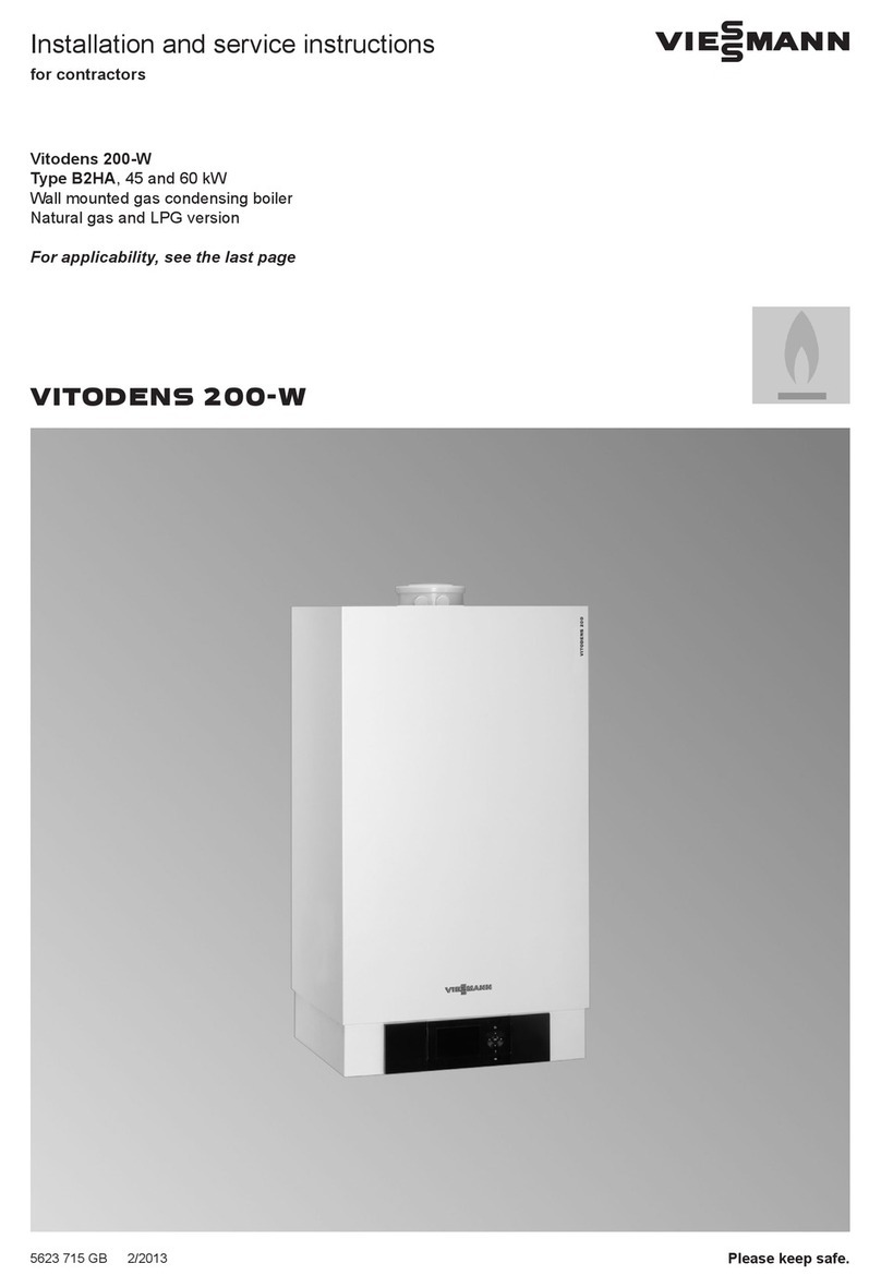
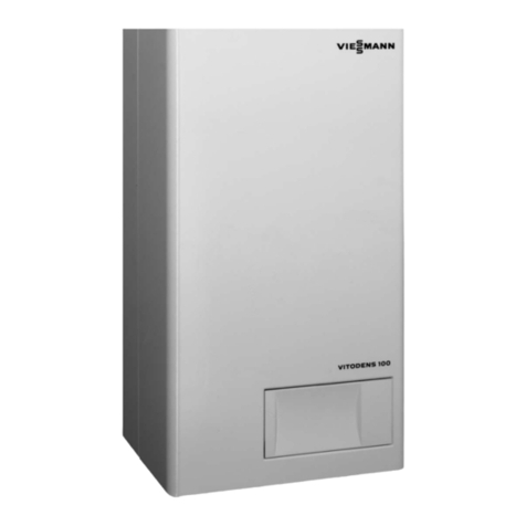
■Vitodens 200-W, type B2HA ............................................................... 9
■System examples ............................................................................... 9
■Spare parts lists .................................................................................. 9
2. Preparing for installation ................................................................................................................ 10
3. Installation sequence Mounting the boiler and making connections ........................................ 12
■Fitting the wall mounting bracket ........................................................ 12
■Hooking the boiler onto the wall mounting bracket and levelling it ..... 13
Connection on the heating water side ................................................... 13
■Connection set with integral low loss header ..................................... 14
■Connection set without low loss header ............................................. 15
Flue gas connection ............................................................................... 15
Condensate connection ......................................................................... 16
Gas connection ...................................................................................... 16
Opening the control unit enclosure ........................................................ 16
Electrical connections ............................................................................ 18
■Circulation pump at plug sÖ ................................................................ 19
■Circulation pump at plug sA ................................................................ 22
■External demand via switching contact .............................................. 23
■External demand via 0 – 10 V input .................................................... 23
■External blocking via switching contact .............................................. 24
■Outside temperature sensor ! .......................................................... 25
■Power supply for accessories at plug lH (230 V ~) ............................ 25
■Power supply fÖ ................................................................................. 27
■Routing connecting cables ................................................................. 27
Closing the control unit enclosure and inserting the programming unit . 29
4. Commissioning, inspec-
tion, maintenance
Steps - commissioning, inspection and maintenance ............................ 30
5. Code 1 Calling up coding level 1 ........................................................................ 54
General/group "1" .................................................................................. 54
Boiler/group "2" ...................................................................................... 56
DHW/group "3" ...................................................................................... 57
Solar/group "4" ....................................................................................... 57
Heating circuit 1, heating circuit 2, heating circuit 3/group "5" ............... 58
6. Code 2 Calling up coding level 2 ........................................................................ 63
General/group "1" .................................................................................. 63
Boiler/group "2" ...................................................................................... 69
DHW/group "3" ...................................................................................... 70
Solar/group "4" ....................................................................................... 71
Heating circuit 1, heating circuit 2, heating circuit 3/group "5" ............... 74
7. Diagnosis and service
scans
Service level .......................................................................................... 80
Diagnosis ............................................................................................... 81
■Operating data .................................................................................... 81
■Brief scan ............................................................................................ 81
Checking outputs (relay test) ................................................................. 84
■Weather-compensated control unit ..................................................... 84
■Constant temperature control unit ...................................................... 84
8. Troubleshooting Fault display ........................................................................................... 86
■Weather-compensated control unit ..................................................... 86
■Constant temperature control unit ...................................................... 86
Index
Index
5817493


