manuals.online logo
Brands
  1. Home
  2. •
  3. Brands
  4. •
  5. Viessmann
  6. •
  7. Control Unit
  8. •
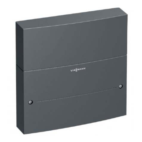
  9. Viessmann VITOTRONIC 200 Operating instructions

Viessmann VITOTRONIC 200 Operating instructions

Other manuals for VITOTRONIC 200

15

This manual suits for next models

1

Other Viessmann Control Unit manuals

Viessmann VITOTRONIC 200 Operating instructions

Viessmann

Viessmann VITOTRONIC 200 Operating instructions

Viessmann AM1 User manual

Viessmann

Viessmann AM1 User manual

Viessmann EM-P1 Operating instructions

Viessmann

Viessmann EM-P1 Operating instructions

Viessmann 5578 User manual

Viessmann

Viessmann 5578 User manual

Viessmann 5214 User manual

Viessmann

Viessmann 5214 User manual

Viessmann 5210 User manual

Viessmann

Viessmann 5210 User manual

Viessmann 5223 User manual

Viessmann

Viessmann 5223 User manual

Viessmann VITOCAL 150-A Operating instructions

Viessmann

Viessmann VITOCAL 150-A Operating instructions

Viessmann 5561 User manual

Viessmann

Viessmann 5561 User manual

Viessmann 5546 User manual

Viessmann

Viessmann 5546 User manual

Viessmann EM-EA1 extension Operating instructions

Viessmann

Viessmann EM-EA1 extension Operating instructions

Viessmann 5205 User manual

Viessmann

Viessmann 5205 User manual

Viessmann 5220 User manual

Viessmann

Viessmann 5220 User manual

Viessmann VITOTRONIC 100 Instruction manual

Viessmann

Viessmann VITOTRONIC 100 Instruction manual

Viessmann VITOSOLIC 100 Operating instructions

Viessmann

Viessmann VITOSOLIC 100 Operating instructions

Viessmann VITOTRONIC 300 Instruction manual

Viessmann

Viessmann VITOTRONIC 300 Instruction manual

Viessmann VITOSOLIC 200 Quick guide

Viessmann

Viessmann VITOSOLIC 200 Quick guide

Viessmann GC1 Guide

Viessmann

Viessmann GC1 Guide

Viessmann SM1 Quick guide

Viessmann

Viessmann SM1 Quick guide

Viessmann VITOSOLIC 200 Quick guide

Viessmann

Viessmann VITOSOLIC 200 Quick guide

Viessmann VITOTRONIC 100 Quick guide

Viessmann

Viessmann VITOTRONIC 100 Quick guide

Viessmann 5205 User manual

Viessmann

Viessmann 5205 User manual

Viessmann VITOTRONIC 300-K User manual

Viessmann

Viessmann VITOTRONIC 300-K User manual

Viessmann SDIO/SM1A Quick guide

Viessmann

Viessmann SDIO/SM1A Quick guide

Popular Control Unit manuals by other brands

Seitz 14A80 user manual

Seitz

Seitz 14A80 user manual

Wilo RS485 Installation and operating instructions

Wilo

Wilo RS485 Installation and operating instructions

Becker CentralControl CC41 Commissioning Instruction

Becker

Becker CentralControl CC41 Commissioning Instruction

SICK CDB650 operating instructions

SICK

SICK CDB650 operating instructions

Panduit NetKey NKP5E88M Series installation instructions

Panduit

Panduit NetKey NKP5E88M Series installation instructions

MX Options Concentric Petite Fitting instructions

MX

MX Options Concentric Petite Fitting instructions

Clean Water Systems Fleck 2510 Installation & start?up guide

Clean Water Systems

Clean Water Systems Fleck 2510 Installation & start?up guide

Fairchild FSB44104A user guide

Fairchild

Fairchild FSB44104A user guide

LEGRAND Wattstopper LMIN-104 installation instructions

LEGRAND

LEGRAND Wattstopper LMIN-104 installation instructions

PMK ATT10BNCS instruction manual

PMK

PMK ATT10BNCS instruction manual

Tektronix TDS3FFT user manual

Tektronix

Tektronix TDS3FFT user manual

Woodward easYgen Technical manual

Woodward

Woodward easYgen Technical manual

Balluff BNI EIP-502-105-R015 user guide

Balluff

Balluff BNI EIP-502-105-R015 user guide

NXP Semiconductors TWR-LS1021A Getting started

NXP Semiconductors

NXP Semiconductors TWR-LS1021A Getting started

Advantech PCM-3117 Startup manual

Advantech

Advantech PCM-3117 Startup manual

Danfoss MCO 101 manual

Danfoss

Danfoss MCO 101 manual

Moons' Lin Engineering R701P user manual

Moons'

Moons' Lin Engineering R701P user manual

Aventics RV1 operating instructions

Aventics

Aventics RV1 operating instructions

manuals.online logo
manuals.online logoBrands
  • About & Mission
  • Contact us
  • Privacy Policy
  • Terms and Conditions

Copyright 2025 Manuals.Online. All Rights Reserved.

VIESMANN
Installation and service
instructions
for contractors
Vitotronic 200
Type KW1
Weather-compensated, digital boiler control unit
For applicability, see the last page
VITOTRONIC 200
5862 699 GB 8/2008 Please keep safe.
Please follow these safety instructions closely to prevent accidents and
material losses.
Safety instructions explained
Danger
This symbol warns against the
risk of injury.
!Please note
This symbol warns against the
risk of material losses and
environmental pollution.
Note
Details identified by the word "Note"
contain additional information.
Target group
These instructions are exclusively
designed for qualified personnel.
&Work on gas equipment must only
be carried out by a qualified gas fit-
ter.
&Work on electrical equipment must
only be carried out by a qualified
electrician.
&The system must be commissioned
by the system installer or a qualified
person authorised by the installer.
Regulations
Observe the following when working
on this system
&all legal instructions regarding the
prevention of accidents,
&all legal instructions regarding
environmental protection,
&the Code of Practice of relevant
trade associations,
&all current safety regulations as
defined by DIN, EN, DVGW, TRGI,
TRF, VDE and all locally applicable
standards.
If you smell gas
Danger
Escaping gas can lead to
explosions which may result in
serious injury.
&Never smoke. Prevent naked
flames and sparks. Never
switch lights or electrical
appliances ON or OFF.
&Close the gas shut-off valve.
&Open windows and doors.
&Remove all people from the
danger zone.
&Notify your gas or electricity
supplier from outside the
building.
&Shut off the electricity supply
to the building from a safe
place (outside the building).
If you smell flue gas
Danger
Flue gas can lead to life-threa-
tening poisoning.
&Shut down the heating sys-
tem.
&Ventilate the boiler room.
&Close all doors leading to the
living space.
Safety instructions
2
Safety instructions
5862 699 GB
Working on the system
&When using gas as fuel, also close
the main gas shut-off valve and
safeguard against unauthorised
reopening.
&Isolate the system from the power
supply and check that it is no longer
'live', e.g. by removing a separate
fuse or by means of a main isolator.
&Safeguard the system against
unauthorised reconnection.
!Please note
Electronic modules can be
damaged by electro-static dis-
charges.
Touch earthed objects, such as
heating or water pipes, to dis-
charge static loads.
Repair work
!Please note
Repairing components which
fulfil a safety function can com-
promise the safe operation of
your heating system.
Replace faulty components
only with original Viessmann
spare parts.
Ancillary components, spare and
wearing parts
!Please note
Spare and wearing parts which
have not been tested together
with the heating system can
compromise its function. Instal-
ling non-authorised compo-
nents and non-approved
modifications/conversion can
compromise safety and may
invalidate our warranty.
For replacements, use only ori-
ginal spare parts from
Viessmann or those which are
approved by Viessmann.
Safety instructions (cont.)
3
Safety instructions
5862 699 GB
Installation instructions
Preparing for installation
System version........................................................................................... 6
Installation sequence
Overview of electrical connections .............................................................. 7
Inserting cables and applying strain relief.................................................... 8
Inserting the boiler coding card ................................................................... 9
Changing the high limit safety cut-out setting (if required) ............................ 10
Changing the thermostat setting (if required) ............................................... 11
Connecting sensors.................................................................................... 13
Connecting pumps...................................................................................... 13
External connection to plug "X12" ............................................................... 15
Burner connection ...................................................................................... 15
Power supply.............................................................................................. 17
Fitting the top part of the control unit ........................................................... 19
Opening the control unit .............................................................................. 21
Service instructions
Commissioning
Controls and display elements .................................................................... 22
Changing the language............................................................................... 22
Testing the high limit safety cut-out ............................................................. 23
Matching coding addresses ........................................................................ 23
Checking outputs (actuators) and sensors................................................... 23
Adjusting the heating curves ....................................................................... 24
Service scans
Service level overview ................................................................................ 28
Diagnosis (temperatures, boiler coding card and brief scans) ...................... 29
Scanning operating conditions .................................................................... 31
Display "Service" ........................................................................................ 32
Troubleshooting
Faults with fault display on the programming unit......................................... 34
Faults that are not displayed at the programming unit .................................. 41
Function description
Boiler water temperature control ................................................................. 44
Heating circuit control ................................................................................. 47
Cylinder temperature control....................................................................... 52
Index
4
Index
5862 699 GB
Codes
Resetting codes to their delivered condition ................................................ 56
Calling up code 1 ........................................................................................ 56
Overview .................................................................................................... 56
Code 2........................................................................................................ 57
Designs
Connection and wiring diagram ................................................................... 72
Components
Components from the parts list.................................................................... 74
Radio clock receiver, part no. 7450 563....................................................... 79
Flue gas temperature sensor, part no. 7450 630 .......................................... 80
Remote control ........................................................................................... 82
Control module V, part no. 7143 513............................................................ 85
KM BUS distributor, part no. 7415 028......................................................... 86
Boiler coding card....................................................................................... 87
Function extension 0-10 V, part no. 7174 718 .............................................. 87
External extension H5, part no. 7199 249 .................................................... 89
Secondary air device Vitoair, part no. 7338 725, 7339 703........................... 92
Parts lists .................................................................................................. 94
Specification............................................................................................. 97
Settings and equipment............................................................................ 98
Keyword index .......................................................................................... 100
Index (cont.)
5
Index
5862 699 GB
One directly connected heating circuit without mixer
ABoiler with Vitotronic 200
BDHW cylinder
CKM BUS subscriber or KM BUS
distributor (only with several KM
BUS subscribers)
DHeating circuit without mixer
(Heating circuit A1)
Plug
!Outside temperature sensor
§Boiler water temperature sen-
sor
%Cylinder temperature sensor
sÖ A1 Heating circuit pump
sA Circulation pump for cylinder
heating
sK DHW circulation pump
fÖ Power supply, 230 V/50 Hz
fA Burner, stage 1
lÖ Burner, stage 2/mod.
aVG KM BUS subscriber/distributor
a:A Two-stage/mod. burner exten-
sion
System version
6
Preparing for installation
5862 699 GB
The illustration shows the lower part of the control unit from the back.
230 V~ plugs
sÖ Heating circuit pump (heating cir-
cuit A1) (accessory)
sA Circulation pump for cylinder
heating (accessories)
sK DHW circulation pump (on site)
fÖ Power supply
fA Burner
X12 External burner start (stage 1)
Low voltage plug
!Outside temperature sensor
§Boiler water temperature sensor
%Cylinder temperature sensor
aG Flue gas temperature sensor
(accessories)
aVG KM BUS subscriber or KM BUS
distributor (accessories)
a:A Two-stage/modulating burner
extension (part of the standard
boiler delivery)
Overview of electrical connections
7
Installation sequence
5862 699 GB
Installation
&When connecting external switching
contacts or components to the low
voltage circuit of the control unit, the
safety requirements of protection
class II, i.e. 8.0 mm air gap/creeping
distance or 2.0 mm insulation thick-
ness from 'live' components must be
observed.
&For all on-site components (incl.
PC/laptops), ensure safe electrical
separation to EN 60 335 or IEC 65.
Inserting cables and applying strain relief
Blank off unnecessary knockouts in the lower part of the control unit with cable
grommets (not cut out).
Overview of electrical connections (cont.)
8
Installation sequence
5862 699 GB
Inserting the boiler coding card
Only use the boiler coding card included with the boiler product documentation
(see also table below).
Boiler Coding card Part no.
Vitola 200, type VB2A, VX2A E1 7818 915
Vitola 222 E1 7818 915
Vitoladens 300-T E1 7818 915
Vitocrossal 300, type CU3 Cb 7818 913
Inserting cables and applying strain relief (cont.)
9
Installation sequence
5862 699 GB
Installation
Insert the boiler coding card through
the cut-out in the cover into slot "X7".
Changing the high limit safety cut-out setting (if required)
In the delivered condition, the high limit safety cut-out is set to 110 °C and can
be adjusted to 100 °C.
Never set the thermostat above 75 °C when adjusting the temperature to
100 °C.
Inserting the boiler coding card (cont.)
10
Installation sequence
5862 699 GB