ENDE
- Zum Anschluss an das Blinkgerät, siehe beiliegende Anlei-
tung für Dreifach-Blinkgeräte. Bitte beachten: die gelben
Kabel sind für die Beleuchtung, die schwarzen für das
Blaulicht – die Kabel sind paarweise.
- Möchten Sie Ihr Modellauto auf der Anlage fixieren, so
können Sie dies mit einem handelsüblichen Sekundenkle-
ber oder mit Hilfe zweier Gummiringe machen. Bitte beach-
ten Sie, dass die Verwendung von Klebstoff bei einem evtl.
notwendigen Auswechseln der Glühlampe zu Problemen
führen kann.
Zum Fixieren des Modellautos mittels Gummiringen bohren
Sie bitte zunächst auf Höhe der beiden Achsen je ein Loch
in die Anlage. Ziehen Sie nun je einen Gummiring über die
beiden Achsen und führen diesen durch die Bohrung unter
die Anlage. Dort werden die Gummienden dann verknotet.
3. Glühlampenwechsel
3.1 Beleuchtung
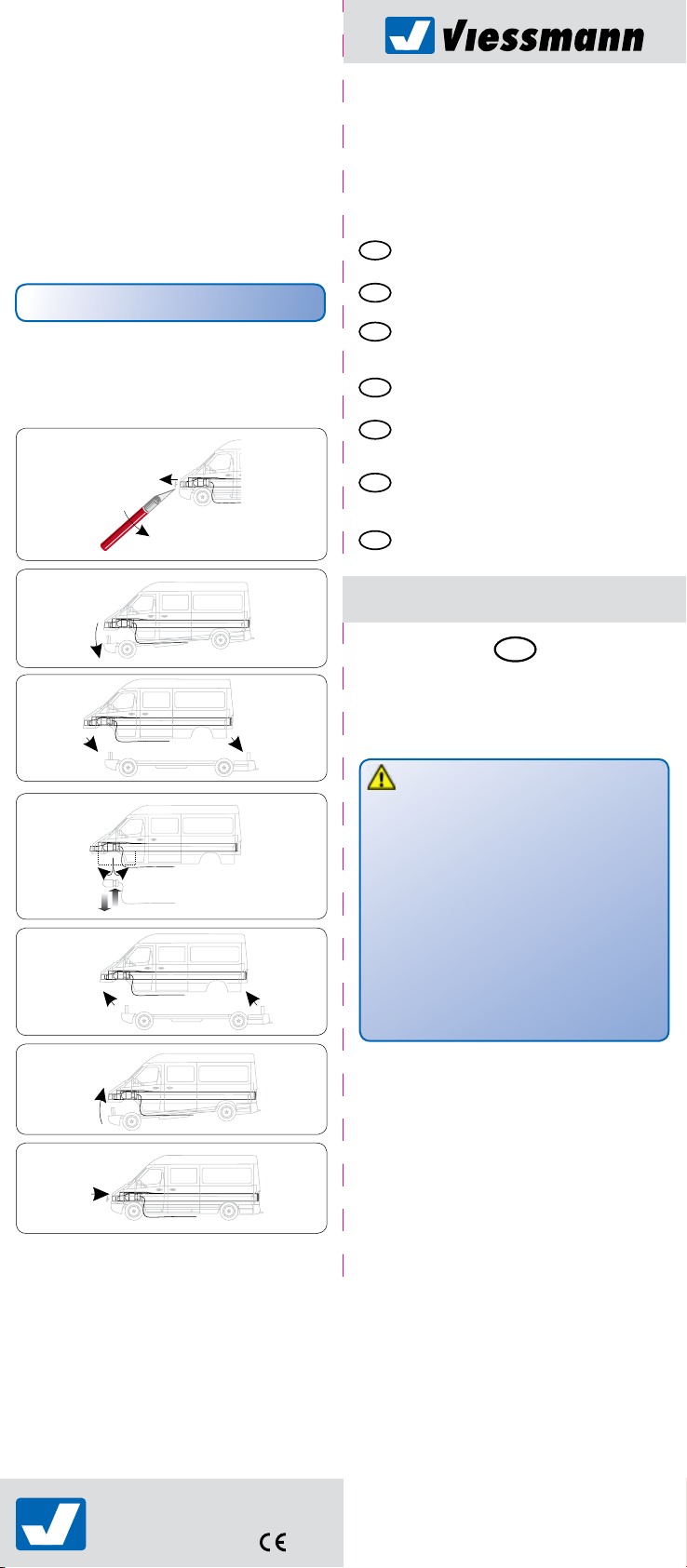
- Nehmen Sie das Modellauto von der Anlage herunter.
- Lockern Sie nun mit einem spitzen Gegenstand vorsichtig
die vordere Stoßstange und ziehen Sie sie nach vorne ab
(Abb. 1).
- Kippen Sie den Unterboden in Pfeilrichtung nach unten
(Abb. 2).
- Ziehen Sie den gesamten Unterboden von der Karosserie
ab (Abb. 3).
- Schneiden Sie die Aluminiumfolie im Bereich der defekten
Glühlampe mit einem spitzen Messer ein und falten Sie die
Folie auseinander. Entfernen Sie nun die defekte Glühlam-
pe und setzen Sie eine neue ein (Abb. 4). Ersatzglühlampe
Art.-Nr. 3505.
- Um eine ausreichende Wärmeabfuhr zu gewährleisten,
muss die Aluminiumfolie wieder über die Glühlampe
gedeckt werden. Montieren Sie nun den Unterboden
wieder an die Karosserie. Gleichzeitig bitte die Lage der
Kabel kontrollieren. Diese sollten so gelegt sein, dass sie
im Bereich des linken Vorderrades austreten (Abb. 5).
- Rasten Sie den vorderen Nummernschildbereich in die
Karosserie ein (Abb. 6).
- Drücken Sie vorsichtig die Stoßstange wieder in die
Karosserie (Abb. 7).
- Führen Sie vor der Montage auf Ihrer Anlage eine
Funktionskontrolle durch.
3.2 Blaulicht
- Nachdem Sie das Modellauto von Ihrer Anlage entfernt
haben, lösen Sie zunächst die Karosserie ab.
Verfahren Sie hierbei, wie in Abschnitt 3.1.
- Lösen Sie nun die Scheiben des Modells vorsichtig heraus.
- Mit einer Spitzzange können Sie die Kabel ca. 1 mm unter-
halb des Sockels anfassen und so die Lampe nach oben
herausschieben.
- Beim Einbau der neuen Blaulichtglühlampe (Art.-Nr. 3505)
nicht von unten an den Kabeln ziehen, sondern die Lampe
vorsichtig von oben in den Sockel drücken.
- Nach Installation der Blaulichtglühlampe kann die Scheibe
wieder angebracht werden. Bei dem restlichen Zusammen-
bau gehen Sie bitte wie in Abschnitt 3.1 beschrieben vor.
4. Technische Daten
Betriebsspannung: 10 – 16 V AC ~ / DC =
Stromaufnahme: ca. 30 mA
1. Important information
Please read this manual completely and attentively before
using the product for the rst time. Keep this manual. It is part
of the product.
1.1 Safety instructions
Caution:
Risk of injury!
Due to the detailed reproduction of the original and the
intended use, this product can have peaks, edges and
breakable parts. For installation tools are required.
Electrical hazard!
Never put the connecting wires into a power socket!
Regularly examine the transformer for damage.
In case of any damage, do not use the transformer.
Make sure that the power supply is switched off when
you mount the device and connect the cables!
Only use VDE/EN tested special model train transformers
for the power supply!
The power sources must be protected to prevent the risk of
burning cables.
1.2 Using the product for its correct purpose
This product is intended:
- For installation in model train layouts and dioramas.
- For connection to an authorized model train transformer
(e. g. item-No. 5200) or a digital command station.
- For operation in dry rooms only.
Using the product for any other purpose is not approved and is
considered incorrect. The manufacturer is not responsible for
any damage resulting from the improper use of this product.
1.3 Checking the package contents
Check the contents of the package for completeness:
- Chassis with LED
- 6 clip logo plates with 3 different DB logos
- Clip logo plate black (without logo)
- 2 feet to glue on
- Manual
2. Mounting
- Remove the car model carefully from the package.
- Check function before mounting.
- Position your model car on the layout and mark the loca-
tions for the emerging cables (invisible behind the wheels).
- Drill a hole (Ø 5 mm) at the marks.
- Push the connection cables through the drilled hole.
- To connect to the blinking unit, refer to the enclosed
manual for triple blinking units. Please observe: the yellow
cables are for the illumination, the black ones for the blue
light - the cables come in pairs.
- If you want to fasten your model car to the layout, you can
do it with a standard superglue or with two rubber bands.
Please note that the use of glue can cause problems dur-
ing an exchange of the bulb should it become necessary.
If you want to fasten the model car with rubber bands, drill
a hole each into the layout at the level of the two axles.
Now pull one rubber band each over the two axles and
push it through the hole. Underneath the layout, both
rubber ends are fastened with knots.
3. Changing the bulb
3.1 Illumination
- Remove the model car from the layout.
- Use a pointed device to carefully loosen the front bumper
and pull it off (fig. 1).
- Tilt the undercarriage downwards in the indicated direction
(fig. 2).
- Remove the complete underbody from the carriage (fig. 3).
- Incise the aluminium foil around the defect bulb and fold
the foil apart. Now remove the defect bulb and replace it
(fig. 4). Spare bulb Item-No. 3505.
- In order to ensure a sufficient heat dissipation, the alumini-
um foil has to be placed over the bulb. Now join the under-
body to the carriage. At the same time check the position
of the cables. They should emerge near the left front wheel
(fig. 5).
- Lock the front number plate part into the carriage (fig. 6).
- Carefully push the bumper into the carriage (fig. 7).
- Before mounting to your layout, carry out a function
control.
32