Viessmann 6840 User manual

Bedienungsanleitung
Operation Manual
6840
H0 Schaltkontakt (Magnetschalter)
H0 Switching contact (magnetic switch)
1. Wichtige Hinweise / Important information ........................................................ 2
2. Einleitung / Introduction..................................................................................... 2
3. Einbau / Mounting ............................................................................................. 3
4. Anschluss / Connection..................................................................................... 3
5. Betrieb mit Digitalsystemen / Operation with digital systems ............................ 4
6. Technische Daten / Technical data.................................................................... 4

2
DE EN
1. Wichtige Hinweise
Bitte lesen Sie vor der ersten Anwendung des Produktes
bzw. dessen Einbau diese Bedienungsanleitung aufmerksam
durch. Bewahren Sie diese auf, sie ist Teil des Produktes.
1.1 Sicherheitshinweise
Vorsicht:
Verletzungsgefahr!
Aufgrund der vorgesehenen Verwendung kann das Pro-
dukt Spitzen, Kanten und abbruchgefährdete Teile auf-
weisen. Für die Montage sind Werkzeuge nötig.
Stromschlaggefahr!
Die Anschlussdrähte niemals in eine Steckdose einfüh-
ren! Verwendetes Versorgungsgerät (Transformator,
Netzteil) regelmäßig auf Schäden überprüfen. Bei Schä-
den am Versorgungsgerät dieses keinesfalls benutzen!
Alle Anschluss- und Montagearbeiten nur bei abge-
schalteter Betriebsspannung durchführen!
Ausschließlich nach VDE/EN-gefertigte Modellbahn-
transformatoren verwenden!
Stromquellen unbedingt so absichern, dass es bei einem
Kurzschluss nicht zum Kabelbrand kommen kann.
1.2 Das Produkt richtig verwenden
Dieses Produkt ist bestimmt:
- Zum Einbau in Modelleisenbahnanlagen und
Dioramen.
- Zum Anschluss an einen Modellbahntransformator
(z. B. Art.-Nr. 5200) bzw. an eine Modellbahnsteuerung
mit zugelassener Betriebsspannung.
- Zum Betrieb in trockenen Räumen.
Jeder darüber hinausgehende Gebrauch gilt als nicht
bestimmungsgemäß. Für daraus resultierende Schäden
haftet der Hersteller nicht.
1.3 Packungsinhalt überprüfen
Kontrollieren Sie den Lieferumfang auf Vollständigkeit:
- Schaltkontakt mit Anschlusskabel
- 2 Unterlegstücke
- Schraube
- Anleitung
2. Einleitung
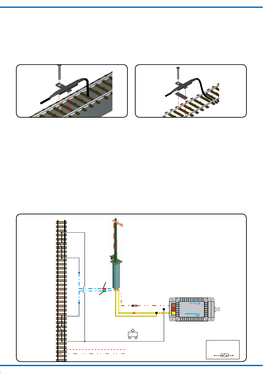
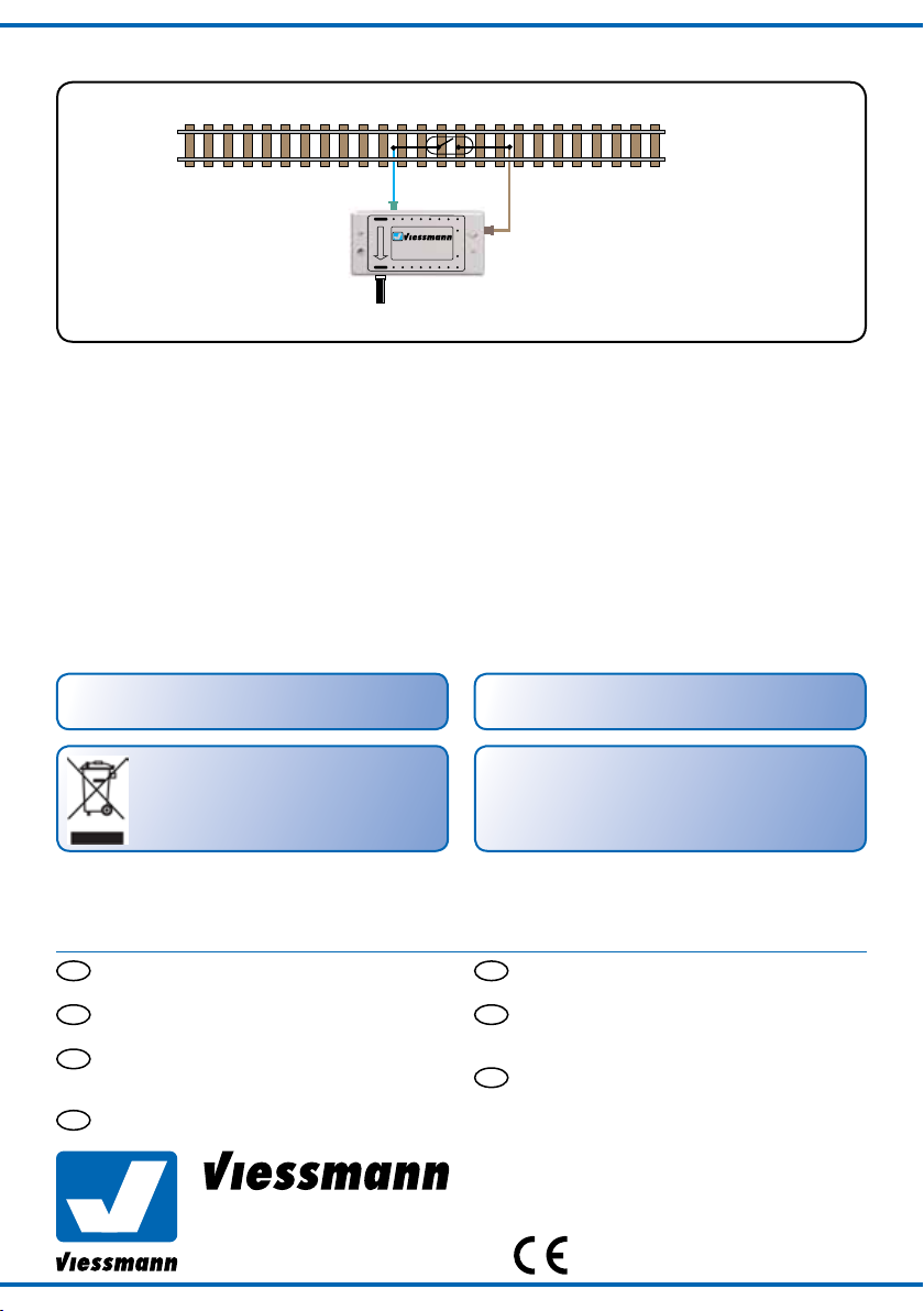
Der Viessmann-Schaltkontakt Art.-Nr. 6840 ist ein berüh-
rungsfreier Magnetschalter zum Auslösen von Schaltvor-
gängen durch den fahrenden Zug. Er wird direkt im Gleis
montiert und ist sowohl mit Zwei- als auch mit Dreileiter-
gleisen verwendbar. Betätigt wird der Schaltkontakt berüh-
rungsfrei durch Fahrzeugmagnete (z. B. Viessmann Art.-
Nr. 6841). Diese können an fast allen H0-Schienenfahr-
zeugen angebracht werden und ermöglichen, dass
fahrende Züge Weichen oder Signale schalten oder Rück-
meldungen beim Betrieb eines Digitalsystems auslösen.
1. Important information
Please read this manual completely and attentively before
using the product for the first time. Keep this manual. It is
part of the product.
1.1 Safety instructions
Caution:
Risk of injury!
Due to the intended use, this product can have peaks,
edges and breakable parts. For installation tools are
required.
Electrical hazard!
Never put the connecting wires into a power socket!
Regularly examine the transformer for damage. In case
of any damage, do not use the transformer.
Make sure that the power supply is switched off when
you mount the device and connect the cables!
Only use VDE/EN tested special model train transform-
ers for the power supply!
The power sources must be protected to prevent the
risk of burning cables.
1.2 Using the product for its correct purpose
This product is intended:
- For installation in model train layouts and dioramas.
- For connection to an authorized model train transformer
(e. g. item-No. 5200) or a digital command station.
- For operation in dry rooms only.
Using the product for any other purpose is not approved
and is considered incorrect. The manufacturer is not re-
sponsible for any damage resulting from the improper use
of this product.
1.3 Checking the package contents
Check the contents of the package for completeness:
- Switching contact with connection cable
- 2 Underlay-pieces
- Screw
- Manual
2. Introduction
The switching contact item-No. 6840 from Viessmann is
able to trigger switches by the running train. It is usable
in combination with two- and three-rail tracks and can be
mounted directly on the tracks. The contact is activated by
a vehicle magnet (e. g. Viessmann item-No. 6841) without
beeing touched. It can be mounted under nearly all H0
track-vehicles and makes it possible to switch turnouts and
signals or to give a feedback to a digital system.

3
Fig. 1
Abb. 1 Fig. 2
Abb. 2
Sekundär
0-10-16 V~
16 V
Primär
230 V~
Gefertigtnach
VDE0570
EN61558
Lichttransformator
5200
Nur für trockene Räume
Primär 230V 50 - 60 Hz
Sekundär max. 3,25 A52 VA
ta 25°CIP 40
10 V
0 V
rote Markierung
red marker
grüne Markierung
green marker braun / brown
gelb / yellow
rot / red
braun / brown
Fahrstrom
track power
z. B. / e. g. 4470/4500/4700/9500
Fig. 3
Abb. 3
Schaltkontakt
switching contact
3. Einbau
Der Schaltkontakt kann durch die Öffnung des Befesti-
gungssteges am Gleis angeschraubt werden (Abb. 1).
Bei Gleisen ohne Bettung sind die beiliegenden Unterleg-
stücke zu verwenden (Abb. 2). Hierbei ist das dünnere für
Fleischmann und das dickere für bettungslose Gleise aller
anderen Hersteller entworfen worden. Die Montage im
Bogen ist nur für Radien ab 358 mm zulässig.
3. Mounting
The switching contact can be screwed on to the tracks by
the hole of the fixing-web (fig. 1). For tracks without
ballast, the enclosed underlay-pieces have to be used (fig.
2). The smaller one is suitable for Fleischmann tracks and
the bigger one for tracks without ballast from all other ma-
nufacturers. Please note, that the mounting in a curve is
only permitted for radii from 358 mm upwards.
4. Anschluss
4.1 Anschluss der Schaltkontakte
Nachfolgend werden einige Möglichkeiten zur Verwendung
der Schaltkontakte dargestellt. Es ist zu beachten, dass an
eine Kontakteinheit jeweils nur ein Antrieb angeschlossen
werden darf, da es sonst zu einer Überlastung und somit
zur Zerstörung des Schaltkontaktes kommt.
Ein Kabel des Schaltkontaktes wird mit einem Pol des Wech-
selstromausganges eines handelsüblichen Modellbahntrans-
formators verbunden. Das andere Kabel ist mit einem der blau-
en Kabel des zu schaltenden Magnetartikels zu verbinden.
4.2 Ansteuerung eines Signals
Schließen Sie das gewünschte Signal gemäß Abb. 3 an.
4. Connection
4.1 How to connect the switching contacts
The following pictures show several possibilities for using
the switching contacts. Please note, that only one drive
can be connected to each contact unit. Otherwise there
can be an overload, so that the contacts can be destroyed.
One wire of the switching contact has to be connected
to one pole of the alternating current exit of a model train
transformer. The other wire has to be connected to one of
the blue wires of the magnetic article.
4.2 Controlling of a semaphore
Connect the signal as shown in fig. 3.

Modellbauartikel, kein Spielzeug! Nicht geeignet für Kinder
unter 14 Jahren! Anleitung aufbewahren!
Model building item, not a toy! Not suitable for children
under the age of 14 years! Keep these instructions!
Ce n’est pas un jouet. Ne convient pas aux enfants de
moins de 14 ans ! C’est un produit décor! Conservez cette
notice d’instructions!
Não é um brinquedo!Não aconselhável para menores de
14 anos. Conservar a embalagem.
Modelbouwartikel, geen speelgoed! Niet geschikt voor
kinderen onder 14 jaar! Gebruiksaanwijzing bewaren!
Articolo di modellismo, non è un giocattolo! Non adatto
a bambini al di sotto dei 14 anni! Conservare instruzioni
per l’uso!
Artículo para modelismo ¡No es un juguete! No
recomendado para menores de 14 años! Conserva las
instrucciones de servicio!
DE
EN
FR
NL
IT
ES
PT
Modelltechnik GmbH
Bahnhofstraße 2a
D - 35116 Hatzfeld-Reddighausen
www.viessmann-modell.de Made in Europe
4
T
T
16
1514
13
1211
109
1
2
3
4
5
67
8
R¸ckmeldedecoder
5217
Richtung Digitalzentrale
zur Digitalzentrale / to the digital command station
Fig. 4
Abb. 4
98668
Stand 02
02/2018
Ho/Me
6. Technical data
Max. switching voltage: 24 V AC~/DC=
Max. contact load: 2 A
6. Technische Daten
Maximale Schaltspannung: 24 V AC~/DC=
Kontaktbelastbarkeit: 2 A
Änderungen vorbehalten. Keine Haftung für Druckfehler
und Irrtümer.
Die aktuelle Version der Anleitung finden Sie auf der Viess-
mann Homepage unter der Artikelnummer.
Subject to change without prior notice. No liability for
mistakes and printing errors.
The latest version of the manual can be looked up at the
Viessmann homepage using the item-No.
Entsorgen Sie dieses Produkt nicht über den
(unsortierten) Hausmüll, sondern führen Sie es
der Wiederverwertung zu.
Do not dispose this product through (unsorted) general
trash, but supply it to the recycling.
Beim Zugbetrieb mit einem Schaltkontakt ist darauf zu
achten, dass das Fahrzeug nicht unmittelbar über einem
solchen zum Stehen kommt. Der so entstehende Dauer-
kontakt könnte zu einem Verschmoren von elektromagne-
tischen Antriebsspulen führen.
Der Abstand zwischen Schaltkontakt und Magnet muss
zwischen zwei und fünf Millimetern betragen. Dies ist
notwendig, um eine ausreichende Magnetwirkung ohne
Magnetisierung des Gleiskörpers sicherzustellen. Sollte
die Magnetkraft nicht ausreichen, können zwei Magnete
hintereinander montiert werden.
5. Betrieb mit Digitalsystemen 5. Operation with digital systems
If you operate with switching contacts it is important, that
the vehicle does not stop directly above a contact. By a
permanent contact the electromagnetic spools could burn.
The distance between the switching contact and the
magnet has to be between two and five millimeters. This
is neccesary to guarantee a sufficient magnetic power and
to guarantee, that the tracks do not get magnetic. If the
magnetic power is not strong enough, two magnets can be
mounted in a row.
Table of contents
Other Viessmann Switch manuals
Popular Switch manuals by other brands

Elite Screens
Elite Screens Kestrel Series Adjustment instructions

Packedge
Packedge SE-5-EP user manual

H3C
H3C LS-3100-16TP-EI-H3-A-O installation manual

Precision Flight Controls
Precision Flight Controls CAT I Setup guide

HP
HP 5120-24G EI TAA Configuration guide

Allied Telesis
Allied Telesis AT-8000S/48 datasheet

Linksys
Linksys EZXS88R - EtherFast Rack Switch Specifications

NEC
NEC QX-S5500G Series installation guide

Olfer
Olfer SR-2400LC manual

Instrumentation Systems & Services
Instrumentation Systems & Services M100 manual

Siemens
Siemens N 523/02 Technical product information

Honeywell
Honeywell NR Series General information