6
7. Das abisolierte Kabel unten verzinnen. Auf den Draht
einen grünen Schrumpfschlauch schieben. Anschluss-
draht eines Widerstandes bis auf 3 mm abschneiden,
verzinnen und mit dem abisolierten Kabel verlöten.
Grünen Schrumpfschlauch über die Lötstelle schieben
und mit Heißluftpistole oder Fön aufschrumpfen (Abb. 5).
8. Das Signal aus dem Schraubstock nehmen und derart
wieder einspannen, dass die Anschlüsse D, E und F zu-
gänglich sind. Einen der Anschlussdrähte oben und unten
abisolieren (vgl. Punkt 6) und oben an den Anschluss E
anlöten. Aufpassen, dass kein Kontakt zu anderen An-
schlussstellen entsteht! Weiter wie bei Punkt 6 und 7.
9. Die beiden letzten Anschlusskabel an beiden Enden
abisolieren und verzinnen. Oben an die Anschlusspunkte
D und F anlöten, dann weiter wie bei Punkt 6 und 7, aber
die gelben Schrumpfschläuche aufziehen. Zur Kontrolle
des korrekten Anschlusses der Drähte an die Kontakte
als auch an die Diode bzw. Widerstände hier eine Zu-
sammenfassung:
M = Messingleiterbahn – Diode (Richtung beachten!)
– schwarzer Schrumpfschlauch
C = Kathode – Widerstand – grüner Schrumpfschlauch
E = Kathode – Widerstand – grüner Schrumpfschlauch
D = Kathode – Widerstand – gelber Schrumpfschlauch
F = Kathode – Widerstand – gelber Schrumpfschlauch
6. Das zweite Kabel, das auf der rechten Seite aus dem
Mast herausragt, oben kurz abisolieren und verzinnen.
Das abisolierte Stück rechtwinklig umbiegen. Durch leich-
tes Ziehen am unteren Ende der Kabel herausnden,
welches Kabel gerade abisoliert wurde und dieses Kabel
so weit aus dem Mastfuß herausziehen, bis oben das
abgeknickte Ende sich in Höhe des Anschlusspunktes
C bendet. Das Kabel an den Anschlusspunkt C anlö-
ten (kurze Lötdauer!). Aufpassen, dass kein Kontakt zur
Messingbahn entsteht! Kabel am unteren Ende 5 mm ab-
isolieren (Abb. 5). Das unten abisolierte Kabel vorsichtig
weiter nach unten ziehen, bis der Anschlussdraht oben
möglichst eng am Signalschirm anliegt.
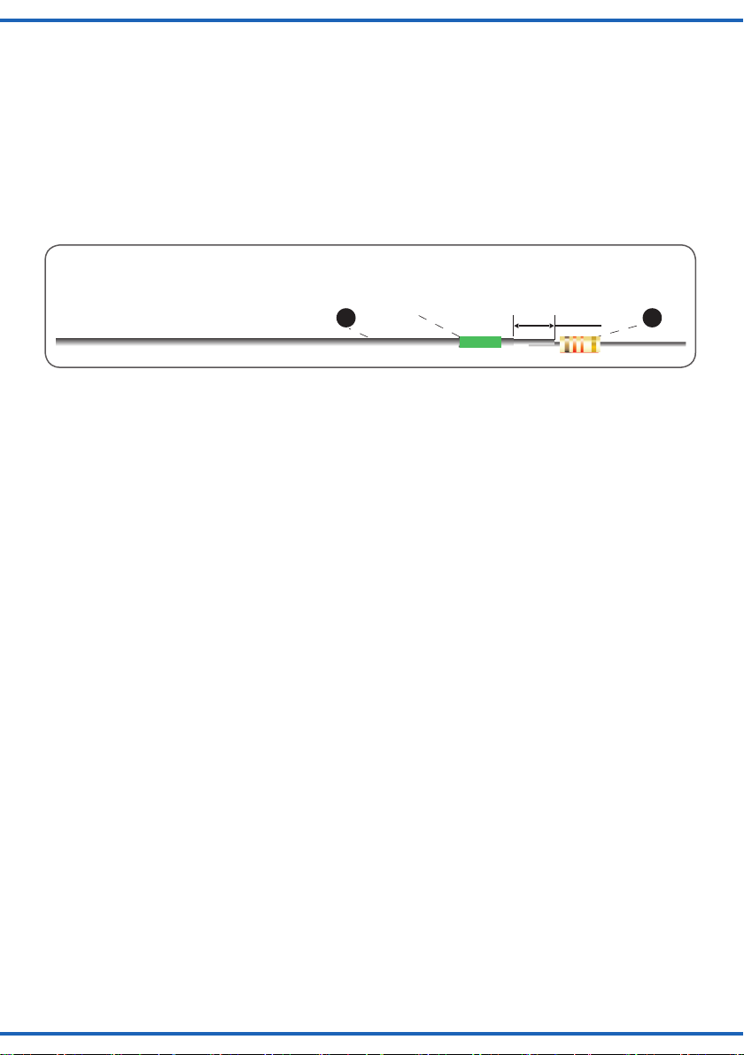
11
10
5mm
Schrumpfschlauch grün
heat shrink tube green
Fig. 5
Abb. 5
10. Führen Sie abschließend eine optische Kontrol-
le durch, dass keine Kurzschlüsse durch zu viel Lötzinn
zwischen den einzelnen Anschlüssen entstehen können.
Prüfen Sie danach äußerst vorsichtig (Pinzette), ob alle
Anschlussdrähte noch fest sitzen. Führen Sie vor dem
Einbau in Ihre Modellbahnanlage unbedingt einen Funkti-
onstest durch: Benutzen Sie den Wechselstromausgang
Ihres Modellbahntrafos (z. B. Lichttransformator Art.-Nr.
5200). Stecker A (Abb. 2) in die Masse-Buchse des Tra-
fos stecken, abwechselnd die Stecker B an die andere
Buchse. Alle Dioden müssen abwechselnd leuchten!
Die darstellbaren Signalbilder sehen Sie in Abbildung 6.
6. Strip the insulation of the second wire projecting in the
right hand side of the mast top and tin-coat it. Bend the
blank part of the wire by 90 degrees. Carefully pull the
bottom ends of the wires to identify, which wire you have
worked on at the top. Pull it downwards until the bent
piece of the wire is inline with the connection point C at
the top. Solder the wire to point C (touch the connec-
tion point only briey with the soldering iron!). Make sure,
there is no electrical connection to the brass conductor
path! Strip 5 mm of the insulation at the bottom end (g.
5). Pull the wire carefully further down until it runs closely
to the signal head at the top.
7. Tin-coat the bottom end of the wire and push a green
heat shrink tubing onto it. Shorten the wire of a resistor
to 3 mm length, tin-coat it and solder it to the wire with
the green heat shrink tubing. Push the green heat shrink
tubing over the soldering point and shrink it with a hot-air
gun or a hair dryer (g. 5).
8. Remove the signal from the vice and reinsert it in such a
manner that the connection points D, E and F are accessi-
ble. Strip the insulation of one wire at both ends (also refer
to step 6) and solder the connector E to the top end. Make
sure there is no electrical contact to any of the other con-
nection points! Proceed as described in steps 6 and 7.
9. Strip the insulation of the 2 remaining wires and tin-
coat them. Solder them to the connection points D and
F at the top and proceed as described in steps 6 and 7,
however, use the yellow heat shrink tubes. The follow-
ing summary serves to assist you when checking the cor-
rectness of the wiring – both at the diode and the resis-
tor ends:
M = Brass conductor path – diode
(observe correct direction!) – black heat shrink tubing
C = Cathode – resistor – green heat shrink tubing
E = Cathode – resistor – green heat shrink tubing
D = Cathode – resistor – yellow heat shrink tubing
F = Cathode – resistor – yellow heat shrink tubing
10. Finally do a visual check in order to make sure there
are no short circuit connections – possibly caused by too
much solder between the individual connection points.
Then check very carefully (using tweezers) if all wires are
rmly soldered. Carry out a function test prior to installing
the signal on your layout: Use the AC output of your trans-
former (e. g. transformer item-No. 5200). Insert plug A (g.
2) into the common socket of the transformer and insert
the plugs B alternating into the other socket. All diodes
must light up alternately! The appropriate signal aspects
are shown in g. 6.