Vighnaharta VCOP GOLD User manual

VCOP Gold User Manual
Vighnaharta Technologies Pvt. Ltd.
Page 2 of 26
Vighnaharta Technologies Pvt. Ltd.
2nd Floor,Karanjkar Estate,
S.N.11/11,Nanded Gaon,
Pune-411041
Tel no.: +919011033259, Sales: +919011033260
Prepared By: LAG
Reviewed By:
Approved By:
Doc No.: RASS/R&D/VCOP_Gold_UM_1_2 Rev
No.: 1_2
Eff Date: 31/01/2015
VCOP GOLD
USER MANUAL
Mfg. By:
Vighnaharta Technologies Pvt. Ltd.
2nd Floor,Karanjkar Estate,S.N.11/11,Nanded Gaon,Pune-411041
Contact no.: +919011033259 (Landline) Sales: +919011033260
Email: sales@vighnaharta.in | Website: http://www.vighnaharta.in

VCOP Gold User Manual
Vighnaharta Technologies Pvt. Ltd.
Page 3 of 26
Table Of Contents
T
ABLE
O
F
C
ONTENTS .............................................................................................................................................................................
2
1.
PRODUCT DESCRIPTION...................................................................................................................4
1.1
OVERVIEW ................................................................................................................................................................... 4
1.2
H
IGHLIGHTED
F
EATURES ....................................................................................................................................................
5
1.3
O
PTIONAL
A
CCESSORIES
P
ROVIDED
W
ITH
T
HE
S
YSTEM .............................................................................................
5
1.4
T
ECHNICAL
S
PECIFICATION ................................................................................................................................................
5
2.
INSTALLATION PROCEDURE............................................................................................................6
2.1
P
REREQUISITES ....................................................................................................................................................................
6
2.2
I
NSTALLING THE UNIT AT THE USER PREMISES.................................................................................................................
6
2.3
WIRING DIAGRAM....................................................................................................................................................... 7
3.
GETTING STARTED ............................................................................................................................8
3.1
U
NDERSTANDING
C
ONTROLS
O
N
F
RONT
P
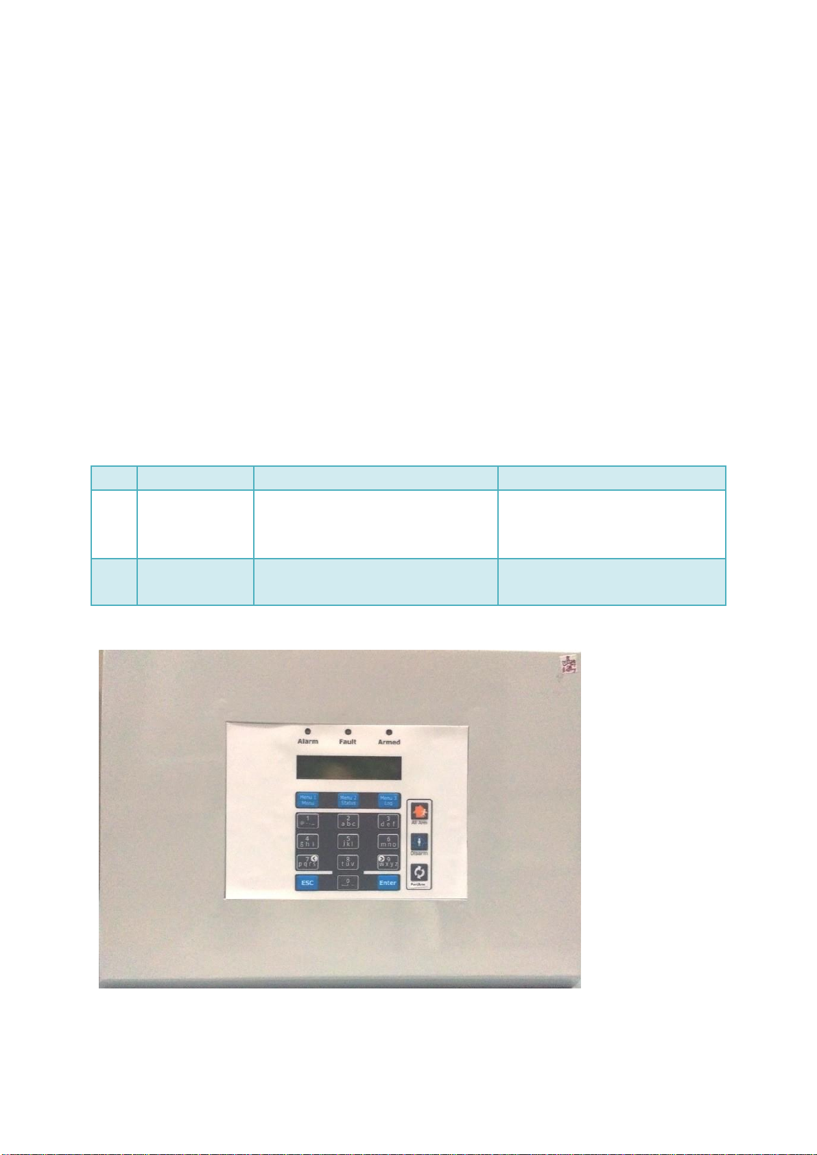
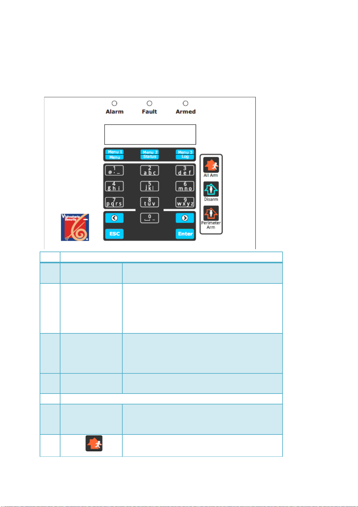
ANEL ............................................................................................................
8
3.2
P
OWER
ONT
HE
S
YSTEM....................................................................................................................................................
9
3.3
V
IEW
E
VENT
L
OG................................................................................................................................................................
10
3.4
S
ETTING
D
ATEAND
T
IME...................................................................................................................................................
10
3.5 R
EBOOT THE
S
YSTEM ...................................................................................................................................................................
11
4.
CONFIGURING THE SYSTEM ................................................................................................................12
4.1
INSTALLER ....................................................................................................................................12
4.1.1
Set PIN...................................................................................................................................12
4.1.2
Delete Log..............................................................................................................................13
4.2
USER...................................................................................................................................................14
4.2.1
User Configuration 1
/
5 .........................................................................................................14
4.2.2
User Configuration 2
/
5 .........................................................................................................17
4.2.3
User Configuration 3
/
5 .........................................................................................................18
Key Fob ..................................................................................................................................................18
4.2.4
User configuration 4
/
5 ..........................................................................................................20
4.2.5
User configuration 5/5............................................................................................................21
8.
OPERATION ............................................................................................................................................22
8.1
A
RMING THE SYSTEM.....................................................................................................................................................
22
8.2
D
ISARMING THE SYSTEM...................................................................................................................................................
23
8.3
E
N
T
RY
/
E
X
I
T
D
E
L
A
Y
......................................................................................................................................................................
23
8.4
A
LARM
R
EPORTING...........................................................................................................................................................
24
APPENDIX....................................................................................................................................................24
Connector Detailsfor zones............................................................................................................25
SYSTEM FAULTS LIST.................................................................................................................................25
GLOSSARY..................................................................................................................................................26

VCOP Gold User Manual
Vighnaharta Technologies Pvt. Ltd.
Page 4 of 26
1. Product Description
1.1
Overview
VCOP Gold is a sophisticated home / office security system for protection against burglary or
property damage. The system is designed to detect intrusion (unauthorized) entry in to building or
area with the help of sensors. The system is kept at the user premises. System can read inputs
from wired as well as wireless sensors. User can configure various parameters like zones, entry /
exit delay, and contact numbers with help of key pad. LCD display on the front panel indicates the
various activities. LED and buzzers are also used to report emergency. At the same time system
reports to the central station by sending SMS and voice call(VCOP Gold-GSM model), Voice
call(VCOP Gold-PSTN model), via Ethernet(VCOP Gold-IP model).
VCOP Gold has following basic models.
No.
Model
Operation
Pre-requisite
1
VCOP Gold GSM
•
Alert through sms and voice call.
•
Remote configuration through
sms/ android app.
SIM card
2
VCOP Gold
PSTN
•
Alert through voice call only.
Telephone line

VCOP Gold User Manual
Vighnaharta Technologies Pvt. Ltd.
Page 5 of 26
1.2
Highlighted Features
•
Battery backup* of 8-12 hours.
•
Key fob has panic key with panic switch.
•
Can connect 8 wired, 1 smoke and 32 wireless zones (including 4 key fobs –panic zones).
•
Zones (sensors) include gas leak detector, door magnetic sensor, fire detector, smoke
detector, PIR sensors, vibration detector.
•
Auto arm and disarm facility.
1.3
Optional Accessories Provided With The System
Item
Arming / Disarming wireless key fob
Wired Sensors for smoke, intrusion, motion and gas leak
Wireless sensors for motion, intrusion
Siren
Telephone cable
Note: Battery backup* - This back up is claimed without sensors connected to the unit.
1.4
Technical Specification
Power Supply
Adaptor of 15V/2A or External battery of 12V /1Ah –4.5 Ah
Rechargeable battery backup.
Input
8-Wired sensor inputs.
1-input for smoke detector.
32-Wireless sensor inputs (including 4 key fobs - panic zones).
Dome keypad with 18 keys
Indication
LED indication for
•
Arm
•
Alarm
•
Fault
Output
•
LCD display
•
Audio Buzzer indication for various status (trouble, alarm, entry
delay, exit delay)
•
Siren output (alarm led on)
•
Auxillary relay PFC output (flasher, door latch)

VCOP Gold User Manual
Vighnaharta Technologies Pvt. Ltd.
Page 6 of 26
Size
( 320x220x75)mm ( L x W x H )
Operating
Temperature
-20C° to +55C°
Humidity
0 to 95 % Rh.
Enclosure
Metal
2. Installation Procedure
2.1
Prerequisites ( for GSM panel)
•
Telephone line must be available at user premises or user must have SIM card.
•
The convenient location for mounting the system must be finalized.
•
The wiring from sensors to the system is complete.
•
Number of sensors to be configured and its types must be finalized.
2.2
Installing the unit at the user premises
1.
Run all desired power, siren and hardware contact wires to the panel location.
2.
Remove cabinet required for wiring entry.
3.
Level the cabinet on sturdy wall and mark the mounting holes with a pencil.
Note: The height of the unit from the flooring must be appropriate so that user can easily
view the indications on the front panel.
4.
Insert the screws into the top mounting holes partially and hang the cabinet on screws.
5.
Tight all the screws of the cabinet and check the fitments.
6.
Connect LAN cable to the Ethernet connector for VCOP Gold–IP model, Put SIM card inside
PCB for VCOP Gold GSM model, Connect Landline cable to the PSTN PCB for VCOP Gold PSTN
Model.
Note: According the product requirement and application make the proper connection.

VCOP Gold User Manual
Vighnaharta Technologies Pvt. Ltd.
Page 7 of 26
7.
Connect sensor cables to the connector.
8.
Do the configuration for zones as mentioned in zone Configuration section.
2.3
Wiring Diagram
The figure shows wiring in detail. Different wireless sensors, siren, smoke detector connections are
as per the diagram.
Note: End Of Line resistor of 4.7 k ohm is connected across every smoke zone.
The following components are included in the unit as per VCOP model.
Components
VCOP GSM
VCOP PSTN
Battery: 12V, 1 to 4.5 AH battery pack
√
√
Host board (Controller)
√
√
Console board (keypad)
√
√
VAD board
√
X
GSM module
√
X
PSTN module
X
√

VCOP Gold User Manual
Vighnaharta Technologies Pvt. Ltd.
Page 8 of 26
3. Getting Started
3.1
Understanding Controls On Front Panel
1
LED Indicators
1.1
Arm
Blue LED Glows till system is in armed state. It
becomes off if system is disarmed.
1.2
Alarm
Red LED indicates alarm condition. When system
receives alarm condition, red LED glows & buzzer
becomes ON. During alarm conditions, siren beeps for
few minutes.
Note: User can change siren ON time.
1.2
Fault
Yellow LED indicates fault / trouble related to zones or
system. Then buzzer becomes on.
For example, fault related to the system - no battery,
no siren, enclosure tamper.
2
LCD Display
16x2 LCD shows the status of the system, configurable
menus and settings.
3
Dome Keypad
3.1
ESC
Exits from the current menu and opens the previous
menu. For example, if you are in zone configuration,
you can reach to Select Options menu.
3.2
All Arm
Allow to arm the system. If user presses this key, exit
delay starts.

VCOP Gold User Manual
Vighnaharta Technologies Pvt. Ltd.
Page 9 of 26
VCOP GOLD
25/08/2012 3:58
3.3
Disarm
Allow to disarm the system. User has to provide correct
password to disarm the system.
3.4
Perimeter
Arm
Allow to arm the system. If user presses this key, exit
delay starts.
3.5
Enter
Enters the data into system.
3.6
M1
Menu key1. In disarmed state, it allows user to select
various menus for setting date and time, system
configuration and reboot.
3.7
M2
Menu key2. In disarmed state, it shows the network
strength in %. (For models installed with GSM module)
3.8
M3
Menu key3. In disarmed state, it allows user to view
event log.
3.9
Alphanumeric keys
Combinations of alphanumeric keys (10 keys) allow
entering various text messages as well as settings,
passwords and so on.
Forward: To move forward, press Forward
Backward: To move backward, press Backward
Note: For editing the data, user has to first go to the
particular letter. While moving cursor by a single digit,
user has to press Lock followed by Forward / Backward
key.
3.2
Power ON The System
Check the proper wiring and connection before power ON the system, insert the adapter of the
system into power socket and put it ON.
After reading zones connected to the system, VCOP GOLD as a stand by message on first line,
date and time on second line appears as shown below.
Then system checks for the system level faults. If any fault exists in the system, faults scroll on
the display putting Fault indicator ON.
To change this message “VCOP GOLD”, go to Config --> System --> User Config 2 /5 --> Syst-
Name.

VCOP Gold User Manual
Realty Automation & Security Systems Pvt. Ltd.
Page 10 of 26
17) System Event
05:39:17 29/08
System Disarmed
By User No: 01
SELECT OPTIONS:
Date Time Config
3.3
View Event Log
The events occurred during the system operations are recorded by the system. The events include
events like power fail, arm, disarm, low battery and so on. The event appears along with date and
time. System can store 99 events. When system is in disarm condition, then only user can view
the event log.
To view event log,
1.
Press M3 key.
2.
Press ““key or ““ key to scroll and view events.
The following 2 displays toggle for typical system disarmed event.
Every entry shows the following details (with above example data).
1.
Event Number (17)
2.
Event Type (System Event)
3. Time (05:39:17)
4. Date (29/08)
5.
Event Description (System Disarmed)
6.
Event parameter (User No: 01)
3.4
Setting Date and Time
Press M1 key, the following message appears.
To set date,
1.
Press M1 key.
2.
Press ““/ ““key while editing the date.
3.
Press alphanumeric key and enter the desired date.
4.
Press Enter key.
To set time,
1.
Press M2 key.
2.
Press ““/ ““key while editing the time.
3.
Press alphanumeric keys and set the desired time.
4.
Press Enter key.

VCOP Gold User Manual
Realty Automation & Security Systems Pvt. Ltd.
Page 11 of 26
SELECT OPTIONS:
Date Time Config
SELECT OPTIONS:
Reboot
3.5
Reboot the System
To restart the system, press M1 key. The following message appears as shown below.
Press Enter key. The following message appears as shown below.
Press M1 key. The system resets and starts again.
Note: Avoid reboot in battery mode.

VCOP Gold User Manual
Realty Automation & Security Systems Pvt. Ltd.
Page 12 of 26
SELECT OPTIONS:
Date Time Config
PIN REQUIRED
ENTER PIN: xxxx
SELECT OPTIONS:
Installer User
SELECT OPTIONS:
Installer User
Inst Config 1/1
Set PIN Del Log
SELECT OPTIONS:
Inst User Dures
4. CONFIGURING THE SYSTEM
There are two types of users of the unit. The different configurations are available to these users.
To enter in this menu press M1 key to select option “Config “on keypad of the system.
As this the configuration menu it is password protected, so user have to enter the password, the
system will “PIN REQUIRED “as a stand by message on first line, “ENTER PIN: xxxx” on second
line and appears as shown below.
If user is installer, user has to enter password for installer. The LCD appears as shown below.
This menu is categorizes as Installer and User (from 1 to 4). Installer has administrative rights.
Installer can assign and change the pins of the user. When user enters a pin, according to
category, the menus are available.
Note: Menus for the installer are not available to users from 1 to 4.
4.1
INSTALLER
To select Config menu, press M3 key. Enter the pin of the installer. The following message
appears.
Press M1 key. The following message appears.
4.1.1
Set PIN
Installer can set PIN for installer, other users and duress.
Press M1 key. The following message appears.

VCOP Gold User Manual
Realty Automation & Security Systems Pvt. Ltd.
Page 13 of 26
Inst Config 1/1
Set PIN Del Log
Wait For Action
Deleting Log
Event Log Erased
Press ESC
To select Inst, press M1 key.
To select User, press M2 key.
To select Dures, press M3 key.
Inst
The system allows configuring password for
installer.
Set InstallerPIN
Enter PIN: xxxx
Enter password as 4 digit
numeric characters. Also user
can modify it. Press Enter key to
save the PIN.
User
The system allows configuring 4 authenticated
users. Each user has password.
Set USERPIN(1-4)
User:x PIN:xxxx
Enter numbers from 1 to 4 as
desired, and password as 4 digit
numeric characters. Also user
can modify it. Press Enter key to
save the user and PIN.
Dures
In case of emergency or panic situation, if user
is forced to disarm the system, user is
supposed to enter duress PIN instead of disarm
PIN. Then system sends alert to desired users
silently, but on the front panel it shows the
disarm message.
Note: Do not set Duress PIN unless it is
absolutely necessary. Its use often results in
false alarm.
Enter 4 digits PIN as numeric
characters and press Enter key
to save the PIN.
Set Duress PIN:
Enter PIN: xxxx
4.1.2
Delete Log
Installer can delete the event log of the system.
To delete the event log,
Press M3 key in disarmed state. The following message appears as below.
To exit from this menu press the ESC key to enter the pervious menu or to exit on main screen.

VCOP Gold User Manual
Realty Automation & Security Systems Pvt. Ltd.
Page 14 of 26
CONFIG OPTIONS:
System GSM PSTN
User Config 1/5
Zone Timers
4.2
USER
To select Config menu, press M3 key. Enter the pin of the desired user. If user is user from 1 to
4, the following message appears.
Note: GSM menu is shown if VCOP has GSM module installed. PSTN menu is shown if VCOP has
PSTN module for landline telephone installed.
To select System configuration, press M1 key. Then the following message appears.
In System configuration there are 5 menus as given in the following table. Press Enter key to go
to the next configuration menu.
System Configuration Menu
LCD Display
1
User Configuration 1 / 5
User Config 1/5
Zone Timers
2
User Configuration 2 / 5
User Config 2/5
Syst-Name PAN.ID
3
User Configuration 3 / 5
User Config 3/5
Keyfobs Sensors
4
User Configuration 4 / 5
User Config 4/5
AutoArm Defaults
5
User Configuration 5/5
User Config 5/5
AutoDisarm
4.2.1
User Configuration 1 / 5
To select Zone configuration, press M1 key.
To select Timers configuration, press M3 key.
Zones
To select Zone configuration, press M1 key.
Zones are nothing but wired or wireless sensors. User can configure different zones. The system
allows 8 wired zones, 1 fire zone and 32 wireless zones (including 4 key fobs –panic zones). User

VCOP Gold User Manual
Realty Automation & Security Systems Pvt. Ltd.
Page 15 of 26
ZONE CONFIG:
Zone No:
can configure various parameters for zones. While editing the parameters, use left and right keys
for backward and forward movement of cursor and alpha numeric keys for modifying the text.
The following table explains parameters related to zones.
Enter 2 digit zone no by numeric keys and press Enter key. LCD display shows configured zone
status as active or bypass at 1st line and asks for its opposite action at 2nd line.
To understand the zone configuration, consider example of zone 1.
Parameter
name
Description
Data
Zone No:
Zone is recognized by
the number as well.
The zone number is two digit number. The
zone number starts from 01 to 41.
Zone Active /
Here zone is
To bypass the zone, press M1 key and press
Bypassed
configured as Active
ESC key. The previous menu appears on
01:Zone Active
asks for bypass. If
LCD.
Bypass?
zone is active press
Enter key for further
To activate the zone, press M1 key. User has
to configure zone parameters.
zone configuration. If
it is bypassed then 1st
activate & then press
Enter key for further
zone configuration.
Zone name
01:Edit ZoneName
Fire zone
The zone name is
name of the particular
zone or set to user
reference as its
location.
Initially each zone from 01 to 37 is named in
the system by default. User can modify it.
Press Enter key to save the name.
Zone trigger
01:Edit Trigger
24 Hrs
This is the trigger
type of the particular
zone. The zones are
classified as interior
or perimeter type.
Interior means inside
the building.
Perimeter means
outside the building
but inside the
premises, typically in
the garden, near gate
There are 5 trigger types.
1.
Perimeter delay: Perimeter zone
2.
24 Hrs
3.
Interior instant
4.
Perimeter Instant
5.
Interior delay
To change the type use forward (-->) and
backward (<--) arrow key.
By default, zones have assigned desired
trigger type. User can modify it. Press Enter
key to save the trigger type assigned to the
zone.

VCOP Gold User Manual
Realty Automation & Security Systems Pvt. Ltd.
Page 16 of 26
SELECT OPTIONS:
Siren Entry Exit
or so on. Once any
zone triggers, system
gets alert. Then
system either starts
giving alarm
immediately or after
some defined delay
depending up on the
zone trigger type.
Note: When trigger type has delay, user can
disarm the system within defined delay time.
If no action is taken by the user, then system
starts alarm. In case of 24 Hrs, system gives
alert for tripped zone all the time, no delay is
provided.
Zone type
01:Edit ZoneType
Fire
This is type of the
wired or wireless
zone. This parameter
indicates the sensor
type. For e.g. At
zone 1 smoke sensor
is connected, select
this parameter a fire,
if motion sensor
connected select it as
a Motion & so, on. To
change the type use
forward (-->) and
backward (<--) arrow
key.
There are 10 zone types.
1.
Intrusion
2.
Fire
3.
Motion
4.
Gas Leak
5.
Tamper
6.
Panic
7.
Supervision
8.
Vibration
9.
Heat
10.
Other
By default, zones have assigned desired zone
type. User can modify it. Press Enter key to
save the zone type assigned to the zone.
Note: User can use more than one zone with
same zone type. For example, Zone 1, 5 and
8 can have zone type as Intrusion. Zone 6
and 7 can have zone type as Motion.
Siren Active/
This is to set the zone
To bypass the already active siren, press M1
bypass
siren as active or
key. To active the already bypassed siren,
01:Siren Active
bypass (silent) for
press M1 key.
Bypass?
wired or wireless
Note: To save the all selected configuration
zone.
parameters press Enter key form this menu.
Timer
To select Siren configuration, press M1 key.
To select Entry delay configuration, press M2 key.
To select Exit delay configuration, press M3 key.
To select Periodic delay and Schedule Configuration, press Enter Key then M1 key.

VCOP Gold User Manual
Realty Automation & Security Systems Pvt. Ltd.
Page 17 of 26
Set Siren Ontime
(01-20)min : 01
User Config 2/5
Syst-Name PAN ID
Edit System Name
V-COP Gold
To understand the Timers we take the example of Siren.
Siren
This is the time during which
siren continues to blow after
alarm condition occurs.
Enter the
desired.
Note: By
minute.
number
default
from 1
the siren
to
on
20 min
time is
as
1
Entry
This is entry delay of the system.
Enter number from 10 to 90 sec as desired.
Note: By default the Entry on time is 60
seconds
Exit
This is exit delay of the system.
Enter number from 10 to 90 sec as desired.
Note: By default the Entry on time is 60
seconds
Periodic
*
This is periodic delay for frame
transfer of communication
status(If communication is going
on, frame will be sent after every
defined minutes to the
monitoring system).
Enter number from 01 to 15 min as desired.
Note: Applicable for V-cop Gold-IP model
only. By default the Periodic delay is 10
minutes.
Schedule
This Schedule for set Auto arm
and disarm function on timely
set schedule
Select Start menu (M1 key) and enter time in
24Hrs format to enable auto arm
Select End menu (M3 Key)and enter time in
24Hrs format to enable auto disarm panel
4.2.2
User Configuration 2 / 5
To select Syst-Name configuration, press M1 key.
To select PAN ID configuration, press M3 key.
Syst-Name Configuration
This is the stand by message appears on first line of LCD display after power on. User can change
this text message.
1.
Type the desired message at the place of stand by message “V-COP GOLD” with the help
alphanumeric keys.

VCOP Gold User Manual
Realty Automation & Security Systems Pvt. Ltd.
Page 18 of 26
User Config 3/5
Keyfobs Sensors
Keyfob1 Absent
Activate
Disarm
key
Perimeter
Arm key
LED
indication
for key press
Panic
key
Arm
key
Note: For forward or backward movement, press Arm/Disarm (Lock) key and then forward or
backward arrow key and you can only enter the 16 small caps character message.
2.
Press Enter key to save the stand by message.
Panel ID Configuration
This will set the Panel Id of that particular system. There can be various panels connected at the
site; this parameter helps to collect data from particular panel number.
Note: This menu is valid for V-cop Gold-IP Model.
4.2.3
User Configuration 3 / 5
To select Key fobs, press M1 key. The following message appears.
To select Sensors, press M3 key.
Key Fob
Key fob is nothing but remote control of the system. The installation of a remote control is called
learning the key fob. The uninstallation of a remote control is called De-learning the key fob.
System can have max 4 key fobs. If user wishes to install more than one key fob (key fob2-key
fob4), press Enter key and move to next key fob installation.
To install (learn) key fob
1.
Press M1 key to learn a key fob. The following message appears.

VCOP Gold User Manual
Realty Automation & Security Systems Pvt. Ltd.
Page 19 of 26
Keyfob1 Active
Remove
WL.Sensor Option
Activate Remove
Zone:10 Waiting
Trip WL. Sensor
10:Edit ZoneName
WL. Door Sensor
Note: Initially it names keyfob as keyfob1. If keyfob1 is already installed (learned), it shows
keyfob1 Active.
2.
Press any key on key fob. After some time, the following message appears.
3.
To remove or uninstall keyfob1, press M1 key.
Note: In case you lost keyfob1, you can uninstall it by removing the same.
4.
To install more keyfobs, press Enter key and repeat the same procedure.
Sensors
The wireless sensors are installed through this menu.
Note: Initially user has to close all zones.
To install (learn) wireless sensors
1.
Press M1 key. The following message appears.
Note: It shows the zone number on first line and zone name on the second line of the LCD
display. Trip the wireless zone means open and close the zone.
2.
Open the zone to be installed.
3.
Close the zone again. After successful learn system shows its configuration to modify. Shows
Zone name menu.
4.
User must check & modify zone configuration as per its use & requirement. For this refer Zone
configuration section.
This completes the installation & configuration of wireless zone.
Keyfob1 Waiting
Press keyfob key

VCOP Gold User Manual
Realty Automation & Security Systems Pvt. Ltd.
Page 20 of 26
Zone name
Remove Zone:xx
Zone:10 Removed
Press ESC
User Config 4/5
AutoArm Defaults
AutoArm On Zone9
Enable Disable
AutoArm Enabled
Press ESC
AutoArm On Zone9
Enable Disable
To uninstall (de-learn) wireless sensors
1.
Press M1 key. The following message appears.
Note: It shows the zone name on first line and zone number on the second line of the LCD
display.
2.
Press M1 key. The following message appears.
This completes the uninstallation of wireless zone.
4.2.4
User configuration 4 / 5
To select AutoArm press M1 key..
To select Defaults, press M3 key.
AutoArm
System provides automatic arming facility to zone 9. User does not have to arm the zone 9. User
has to Open & Close the Zone 9 for the system to go into arm mode automatically.
Note: Zone 9 trigger type must be delay type.
To enable the AutoArm,
1.
Press M1 key. The following message appears.
2.
Press ESC key to complete the activation.
To disable the AutoArm

VCOP Gold User Manual
ty Automation & Securi
AutoArm Disabled
Press ESC
User Config 4/5
AutoArm Defaults
User Config 5/5
AutoDisarm
AutoDisarm Zone8
Enable Disable
1.
Press M3 key. The following message appears.
2.
Press ESC key to complete the deactivation.
Defaults
Press M3 key to load the default factory settings. When default settings get loaded, all wireless
sensors, keyfobs will be uninstalled. Factory settings for zones and user pin get loaded. After the
default sets up, press ESC key to exit the menu.
4.2.5
User configuration 5/5
To select AutoDisarm press M1 key.
System provides automatic disarming facility to zone 8.When zone 8 activates, system gets disarm
automatically. If this feature enable zone trip will disarm the system. If this feature is disabled,
this zone behaves as a normal zone.
Note: Zone 8 trigger type must be 24 Hrs type.
To enable the AutoDisarm,
1.
Press M1 key. The following message appears.
2.
Press ESC key to complete the activation.
To disable the AutoDisarm,
1.
Press M3 key. The following message appears.
AutoDisam Disble
Real Press ESC
ty Systems Pvt. Ltd. Page 21 of 26
AutoDisarm Enble
Press ESC
Defaults Set
Press ESC
Other manuals for VCOP GOLD
1
Table of contents
Other Vighnaharta Smoke Alarm manuals
Popular Smoke Alarm manuals by other brands

Tunstall
Tunstall 68005/96 User & installation instructions

Ei Electronics
Ei Electronics Ei151TL User instruction

SILENT KNIGHT
SILENT KNIGHT SD505-DUCT installation instructions

Fire-Lite Alarms
Fire-Lite Alarms BG-12LX operating instructions

Faraday
Faraday MPC-6000 Installation, operation and maintenance manual

SmartCell
SmartCell SC-23-0220-0001-99 installation guide