Vigia NM 444 HL User manual

A01.01886-8 REV.: 001A01.01886-8 REV.: 001
Automatic Tires
Pressure System
NM 444 HL
Technical ManualTechnical Manual

A01.01886-8 REV: 001 VALIDITY: 28.11.22
GENERAL INFORMATION
Protection of the Environment:
It is very important to be aware, for this we suggest situate the waste according to the local
laws.
SYMBOLS
In this manual, symbols are used to represent dierent types of information. Each of them is described
below with its correct use:
Important: Failure to comply with these indications may cause in improper handling of the
VIGIA System, causing injury or property damage. Make sure to read these explanations.
Very Important: Failure to comply with these indications may cause damage to people or
things and compromise the operation of the system. Make sure to read these explanations.
Note/Explanation/Observation: Indicates additional information about the use of the
System, its functions and instructions on how to resolve errors.

A01.01886-8 REV: 001 VALIDITY: 28.11.22
TABLE OF CONTENTS
GENERAL INFORMATION ............................................................................. 2
SECTION 1: INTRODUCTION ........................................................................ 3
1.1: PURPOSE AND SCOPE OF THE MANUAL ........................................................3
SECTION 2: ELECTRONIC TIRE CALIBRATOR ........................................... 3
2.1: FUNCTION ...........................................................................................................3
2.2: APPLICATION .......................................................................................................3
SECTION 3: MAIN COMPONENTS ................................................................ 4
3.1: ROTOR SUPPORT ..............................................................................................4
3.2: ROTOR ................................................................................................................5
3.3: INFLATION CONNECTORS FOR TIRES .............................................................6
3.4: IRD VALVE ............................................................................................................7
3.5: ELEMENT TORQUE, ROTOR VALVE ..................................................................8
3.6: BODY COUPLINGS ..............................................................................................8
3.7: CONNECTION BETWEEN BODY COUPLING AND ROTOR ............................12
3.8: NM AIR FILTER ..................................................................................................16
3.9: BLOCKING VALVE ............................................................................................16
3.10: NM 444 CONTROL PANEL ..............................................................................17
3.11: INFLATION MODULE .......................................................................................19
3.12: DEPRESSURIZER MODULE ...........................................................................20
3.13: 2/3 WAY NETWORK SHUNT TO DEPRESSURIZER MODULE ......................20
SECTION 4: TIRE CONNECTIONS .............................................................. 21
4.1: PNEUMATIC DIAGRAM .....................................................................................21
4.2: AIR INTAKE ........................................................................................................27
4.3: AUTOMATIC AIR PURGE VALVE .......................................................................27
SECTION 5: ELECTRICAL CONNECTIONS ............................................... 28
5.1: ELECTRICAL INSTALLATION ............................................................................28
SECTION 6: FUNCTIONING ......................................................................... 29

A01.01886-8 REV: 001 VALIDITY: 28.11.22
6.1: OPERATION .......................................................................................................30
6.2: CHANGES OF STATES ......................................................................................33
6.3: REGULATION OF THE SYSTEM FOR THE CALIBRATION OF TIRES ............35
6.4: INDICATIONS OF LOSSES, DEPENDING ON THE INPUT PRESSURE WITH
REGARD TO THE CALIBRATION PRESSURE ........................................................37
SECTION 7: MAINTENANCE ....................................................................... 38
7.1: AIR FILTER ........................................................................................................38
7.2: DOWNWARD DUCT SYSTEM ...........................................................................38
7.3: HOW TO DETERMINE THE SOURCE OF THE LOSS ......................................38
SECTION 8: FAULT CODES ......................................................................... 39
ATTACHED 1 ................................................................................................. 42
9.1: AUTOMATIC AIR PURGE VALVE .......................................................................42
ATTACHED 2 ................................................................................................. 46
10.1: HOW TO DETERMINE THE CORRECT PRESSURE .....................................46
10.2: SUGGESTED MINIMUM PRESSURE TABLE .................................................47
10.3: TIRES NOMENCLATURE AND ALAPA TABLE OF 2021 .................................49
10.4: CHECK LIST CONTROL ..................................................................................55

A01.01886-8 REV: 001 VALIDITY: 28.11.22
SECTION 1: INTRODUCTIONSECTION 1: INTRODUCTION
Using the wrong tire pressures has a signicant
negative impact on a vehicle's operational ability,
from increased tire wear and fuel consumption
to soil compaction and increased driver fatigue.
Driving with the proper tire pressures for load,
speed and road conditions, maximizes vehicle
mobility and performance in demanding terrain
and conditions, reduces overall operating costs,
improves fuel consumption, increases traction
and safety.
1.1: PURPOSE AND SCOPE OF THE
MANUAL
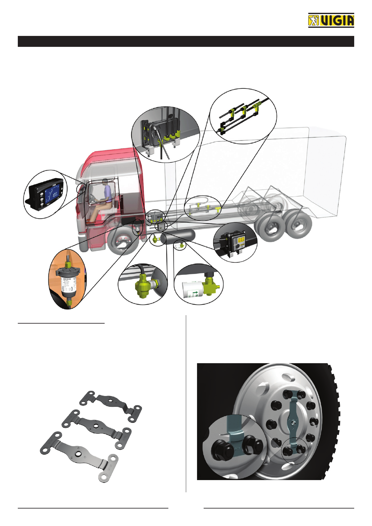
This manual explains how to install and repair
the VIGIA NM 444 ELECTRONIC TIRE
CALIBRATOR, but also includes a basic overview
of system components and operation. It also
provides the necessary information on installation,
full system operation, and troubleshooting.
SECTION 2: ELECTRONIC TIRESECTION 2: ELECTRONIC TIRE
CALIBRATORCALIBRATOR
2.1: FUNCTION
The system allows you to calibrate the tires to a
preset maximum or minimum cold pressure, per
circuit, optimizing the tire pressure with respect
to the load and speed of your vehicle.
2.2: APPLICATION
The VIGIA NM 444 System is particularly useful
when installed on heavy transport vehicles and
especially those that are exposed to dierent
types of roads (including o-road) and conditions
of use including agriculture, livestock, forestry,
transportation fuel, mining and construction.
Very Important: The NM 444 System
can be installed in any unit that has
an air compressor and a power
supply voltage of 12 to 24 V., but its
correct operation will depend on:
• The capacity of the unit's air com-
pressor.
• The number of tires to be con-
trolled in the two pressure states.
• The pressure values at which it is
required to calibrate the tires.
PAGE. 3 OF 55

A01.01886-8 REV: 001 VALIDITY: 28.11.22
SECTION 3: MAIN COMPONENTS
Functions and features of the main system components are described below. The following image shows
the approximate location of each component.
3.1: ROTOR SUPPORT
3.1.1: SPECIFIC SUPPORTS FOR FRONT AND
SIMPLE AUXILIARY AXLES
This element is used in units that, on the steering
and/or auxiliary axle, have an iron or aluminum
disc rim.
3.1.1.1: Installation procedure
a) Remove two nuts diametrically opposed.
b) Put the corresponding mounting.
c) Tight correctly the nuts.
PAGE. 4 OF 55

A01.01886-8 REV: 001 VALIDITY: 28.11.22
Very Important: If the rim is made
of aluminum and the hub of the unit
has iron rim bolts, replace them with
longer bolts.
3.1.2: UNIVERSAL ROTOR SUPPORT FOR
DUAL AXLES (WITHOUT REDUCING HUB)
These brackets are used in dual axles without
reduction hub that have an iron or aluminum disc
rim.
3.1.2.1: Installation procedure
a) Remove four nuts diametrically opposed, two
for side.
b) Put the corresponding mounting.
c) Tight correctly the nuts.
Very Important: If the rim is made
of aluminum and the hub of the unit
has iron rim bolts, replace them with
longer bolts.
3.1.3: UNIVERSAL ROTOR SUPPORT FOR
DUAL AXLES (WITH REDUCING HUB)
These brackets are used in dual axles with
reduction hub that have an iron or aluminum disc
rim.
3.1.3.1: Installation procedure
a) Replace the bolts or nuts indicated for each
brand and model with the studs provided.
b) Put the corresponding mounting.
c) Tight correctly the nuts.
Very Important: Do not use aluminum
rotor supports.dllllllllllebido a podrían
no soportar e--
3.2: ROTOR
Its function is to allow air to pass from a stationary
point on the truck body to the rotating tyres.
3.2.1: INSTALLATION PROCEDURE
No matter the mounting used, the rotor must be
tightened with a moderate torque of approximately
6 ft-lbs. or 8 Nm.
Explanation: The rotor output ter-
minals must be oriented towards the
ination valves, to prevent the ination
connectors from rubbing against the
hub or the rim.
PAGE. 5 OF 55

A01.01886-8 REV: 001 VALIDITY: 28.11.22
3.3: INFLATION CONNECTORS FOR TIRES
Its metallic ends are free (they do not have a valve)
and allow the passage of air in both directions
(from the rotor to the tire and vice versa).
For its application in external tires of dual axles, it
must be complemented with "U" or "L" connectors.
3.3.1: INSTALLATION PROCEDURE
a) Correctly clean, with a tap, the external thread
of the original valve.
b) Remove the internal stem of such valve.
Very Important: If the original valve
of the internal tire has an extension, it
must be removed to avoid possible air
leaks or breaks in the original valve.
Explanation: To thread the valve con-
nector to the internal dual tire, use a
steel reinforced arm. To adjust, use
the INFLATION VALVE WRENCH.
c) Screw on the VIGIA connector, gently tightening
a torque from 2 to 3 lbs. per ft. (2.7 to 4 Nm) with
a wrench.
Very Important: The VIGIA valves
must not rub against the rims and/ or
wheel hubs.
PAGE. 6 OF 55

A01.01886-8 REV: 001 VALIDITY: 28.11.22
3.4: IRD VALVE
As indicated by its initials, it allows ination, retains
air when disconnecting a tire or depressurizing the
network, and allows deation when switching from
Loaded to Unloaded state.
3.4.1: CONNECTING THE VALVES TO THE
ROTOR
Note: On front axles with a decorative
ring, make two holes in its wing and
place rubber grommets to prevent the
edge of the metal sheet from dama-
ging the Push-lok hose.
PAGE. 7 OF 55

A01.01886-8 REV: 001 VALIDITY: 28.11.22
3.5: ELEMENT TORQUE, ROTOR VALVE
14 Nm
8 Nm
de 25 a 31 Nm
2.5 a 4 Nm
3.6: BODY COUPLINGS
VIGIA oers dierent models of body couplings.
These couplings include a supplement that can
be placed either inside or outside the body, fender
or other mounting part, according to the molding
they have.
3.6.1: INSTALLATION PROCEDURE
VIGIA oers several models of body coupling
mountings designed to prevent extending beyond
the vehicle’s body or to avoid perforating fenders,
body or cabin. Make sure the tyre does not rub
against the mounting, even in extreme situations.
3.6.1.1: Steering axles
3.6.1.1.1 Units with cabin and/or fenders with
internal reinforcement (or wing)
a) Align the steering wheels parallel to the body.
b) Hold a plumb line from the fenders, so as the
vertical line passes through the center of the rotor.
c) Make a mark on the fender or bodywork 50 to
90 mm (2") backwards from the vertical plumb.
PAGE. 8 OF 55

A01.01886-8 REV: 001 VALIDITY: 28.11.22
Very Important: It is advisable to
pre-assemble the reinforced arm and
position it. When turning the steering
wheel to one side and to the other,
check that the tire does not touch the
reinforced arm. Otherwise, reposition
it at a dierent distance until it does
not touch the reinforced arm in both
directions.
d) Hold the body coupling mounting onto the
reinforcement and mark both holes.
e) Drill with a Ø 11/64" bit (4 mm) and fasten with
the provided bolts, washers and nuts.
f) Install the corresponding coupling.
3.6.1.1.2 Units with cabin and/or fenders
without internal reinforcement (or wing)
a) Mark a point 2" (50 mm) towards the back of
the vehicle and as close as possible to the edge
of the fender.
Before drilling, make sure that there are no
obstruction inside inside the fender.
If there is any obstruction, nd an unobstructed
spot as close as possible to the point originally
marked.
b) First, drill with a Ø 13/64" (5 mm) bit and then
with a 29/64" (11.5 mm) bit.
c) Install the corresponding coupling.
Note: In cases of trailers with one
directional axle, follow the instructions
described in 3.6.1.1. If not, follow the
instructions from 3.6.1.3.
3.6.1.2: Non steering axles (with body or fenders)
3.6.1.2.1 Single axles
a) Using a plumb, mark a point 15.75" (400 mm)
in front of the axle and as close as possible to the
edge of the fender or body.
b) Procceed as item b) from 3.6.1.1.2.
Explanation: In every unit containing
internal reinforcement (or wing), a
body coupling must be installed using
the mounting, screws, washers and
nuts provided with the system, faste-
ning it to the reinforcement previously
mentioned.
PAGE. 9 OF 55

A01.01886-8 REV: 001 VALIDITY: 28.11.22
3.6.1.2.2 Double axles
Observation: This method is only
applicable if the ination pressure
of tires on both axles is the same.
Otherwise, refer to the method for
single axle.
a) Using a plumb line, determine the center line
between axles.
b) On the determined line, dene a point at tires
level approximately.
c) Proceed as explained in point 3.6.1.1.2.
d) Install the double outlet body coupling.
3.6.1.3: Non steering axles (Without Cabin or
Fenders or with Swivel Cabin)
3.6.1.3.1 Single axles
a) Find a bolt or hole in the chassis approximately
15.75" (400 mm) in front of the tyre’s central line,
an at a height that will avoid any rubbing of the
mounting, even with the suspension working to
load limit.
Note: If there are not bolts or holes in
the unit in that spot, make a 5/8" (16
mm) hole.
b) Take the selected bolt out.
c) Secure the base of the variable body coupling
support with the screw provided for this purpose.
Tighten with a torque of 115 lbs. x ft or 15.89 kg
x m. or 155.92 Nm approximately.
Explanation: The base of the varia-
ble body coupling support must be
with the output hole for the VIGIA
tube oriented downwards to avoid the
accumulation of water inside it.
d) Take the reducer out from the extension and
place in it the body coupling, eliminating the
supplement and placing the washer from the
outside.
e) Cut the required VIGIA hose length and connect
the body coupling with the T or cross joint to be
placed approximately in the middle of the axle.
f) Place the fastening nut on the corresponding
polyamide hose end, insert it in the coupling’s
terminal and secure the hose tightening the nut
by hand.
g) Screw and fasten the reducer in the extension.
A
PAGE. 10 OF 55

A01.01886-8 REV: 001 VALIDITY: 28.11.22
h) Insert the extension in the mounting until
the body coupling remains approximately 5/8"
(16 mm) from the edge of the tyre.
Explanation: Previously, pass the
VIGIA hose through the hole placed in
the mounting.
i) Fasten the mounting nut with a spanner and
secure the extension.
3.6.1.3.2 Double axles
Explanation: This procedure applies
only when the air pressure in tyres of
both axles will be the same. If that is
not the case, refer to the procedure for
single axles.
a) Find a bolt or hole in the middle of both axles
and at a convenient heigth.
Note: If there are not bolts or holes in
the unit in that spot, make a Ø 5/8" (16
mm) hole.
b) Procceed as item 3.6.1.3.1. from b)
PAGE. 11 OF 55

A01.01886-8 REV: 001 VALIDITY: 28.11.22
3.7: CONNECTION BETWEEN BODY COUPLING AND ROTOR
This connection controls the tyre pressure and preserves the tyres inated when the unit is moving
without restricting the suspension, the turning of the wheels, etc.
Note: The positions of the rotor cover are shown in relation to an unloaded unit. ----------
STEERING AXLES NON-STEERING AXLES
PARALLEL TOPARALLEL TO
THE FLOORTHE FLOOR PARALLEL TOPARALLEL TO
THE FLOORTHE FLOOR
NON-STEERING AXLES WITHOUT FENDERS DOUBLE AXLES
PARALLEL TOPARALLEL TO
THE FLOORTHE FLOOR
PARALLEL TOPARALLEL TO
THE FLOORTHE FLOOR

A01.01886-8 REV: 001 VALIDITY: 28.11.22
3.7.1: SET ASSAMBLY
BODY COUPLING
ROTOR COUPLING TERMINAL
ROTOR COVER
ROTOR COVER CURVED FIXING NUT BSP 3/8"
ROTOR COVER CURVE
SPRING 15 X 90
STEEL PIPE
HOSE
SPRING 15 X 90
BODY COUPLING
TERMINAL
RIBBED LOCK WASHER
PAGE. 13 OF 55

A01.01886-8 REV: 001 VALIDITY: 28.11.22
a) Screw the nut on the rotor cover curve as far
as it will go, without forcing and then the serrated
lock washer.
b) Screw the bend in the rotor cover until the
washer cramps t with the cover cramps. Screw
a spring to the rotor cover.
Important: The spring has its connec-
ting end, put the larger end in the bend.
c) Put the other spring, at one of the ends of the
tube, approximately 10 mm (3/8").
Then screw and adjust the coupling terminal into
the body coupling.
BODY
COUPLING
COUPLING
TERMINAL
SPRING
HOSE
Important: The spring has a connec-
ting side, put the smaller diameter
side on the tube.
d) Measure the length of the pipe (before, put
the cover in the rotor) so that the slope takes the
appropriate position.
NON-STEERING AXLES
CUT
Explanation: Cut the pipe at the
appropriate length; remove the burr
and possible cutting edges, if neces-
sary.
STEERING AXLES
CUT
PAGE. 14 OF 55

A01.01886-8 REV: 001 VALIDITY: 28.11.22
e) Cut the Push-lok hose, 36 cm, longer than the
pipe.
Example: If the pipe was cut at 40 cm, the hose
should be 76 cm long.
40 CM
76 CM
f) Insert one end of the hose in the coupling
terminal of the body, then pass the other end of
the hose through the assembly (spring - pipe).
Screw the spring to the body coupling terminal and
introduce the end of the pipe through the spring
and the rotor cover.
BODY
COUPLING
COUPLING
TERMINAL
HOSE
SPRING
PIPE
Note: Use lubricating oil or similar pro-
duct if necessary.
g) Put the spring in the pipe, about 3/8" (10
mm). Verify the hose is not obstructed inside the
assembly, mainly in the bend.
3
h) Insert the coupling terminal into the rotor axle.
Insert the hose in the terminal and fasten the
terminal with a spanner.
i) Put the rotor cover in its place, fastening the nut
with a torque of approximately 6 ft-lbs (8.13 N x
m) to 8 ft-lbs (10.85 N x m).
j) Place the bend in the correct position, to keep
the pipe 5/8" (16 mm) from the tyre’s edge and
secure the bend with the hexagonal nut.
16 mm (5/8")
PAGE. 15 OF 55

A01.01886-8 REV: 001 VALIDITY: 28.11.22
3.8: NM AIR FILTER
3.8.1: FUNCTION
Its function is to lter the air entering the VIGIA
system, retaining the solid impurities.
Note: Maximum allowed pressure, 14
BAR (200 PSI).
Explanation: Liquid impurities must
be eliminated by periodically draining
the air tanks, whether by hand or auto-
matically.
3.8.2: LOCATION
a) Locate this element between the air inlet
(secondary air tank, manifold valve, etc.) and the
VIGIA module.
b) Choose a safe and easy access spot on the
bodywork or chassis in order to clean the internal
ltering element.
c) The filter position will be subjected to the
installer’s criteria.
Foresee possible movements between the lter
and the air tank.
Very Important: In trailers and semi-
trailers, a lter must be installed after
the connection valve, to prevent the
entry of impurities when connecting
and disconnecting (see diagram on
page 23).
3.8.3: INSTALLATION PROCEDURE
Secure with seal to the original pneumatic
network.
3.9: BLOCKING VALVE
3.9.1: FUNCTION
It is a mechanical device that blocks the air outlet
from the tank when there are big air leaks and
the compressor cannot compensate. This device
ensures air pressure for the brakes, suspensions,
etc.
3.9.2: TECHNICAL CHARACTERISTICS
Maximum pressure: 20 BAR (290 PSI).
Opening pressure: There are two models:
6.9 BAR (100 PSI) y 9 BAR (130 PSI).
Temperature range: - 35 ºC a 70 ºC.
3.9.3: APPLICATION
It is applied in any situation where the passage
of air blockage at a certain pressure is required.
PAGE. 16 OF 55

A01.01886-8 REV: 001 VALIDITY: 28.11.22
3.9.4: INSTALLATION PROCEDURE
Note: To adapt the valves to the dife-
rent original threads, several cou-
plings areavailable.
REMOVE THE ORIGINAL PLUG,REMOVE THE ORIGINAL PLUG,
LOCATED IN THE MIDDLE ORLOCATED IN THE MIDDLE OR
UPPER PART AND PLACE THEUPPER PART AND PLACE THE
CORRESPONDING COUPLINGCORRESPONDING COUPLING
INSTALL THE BLOCKING VALVEINSTALL THE BLOCKING VALVE
3.10: NM 444 CONTROL PANEL
It has a module and a panel that, connected to
each other by electrical connections, fulll the
function of a control panel. It is provided to control
3 pressure circuits, in 12 V. or in 24 V.
It should be noted that each pressure circuit can
control 1, 2 and up to a maximum of 3 axles, as
long as they are calibrated at the same pressure.
3.10.1: GENERAL FEATURES
Alarm system with dierent warning sound
levels according to the magnitude of the loss and
ination capacity.
Automatic detection and cancellation due
to network damage, or tire blowout and/or
completely deated tire (undercut).
Calibration range in Unloaded state: from 1
BAR to 11 BAR.
Calibration range in Loaded state: from 3.5
BAR to 11 BAR.
Detection of excessive loss of air.
Inhibition of alarms during contact and without
inlet pressure, until the unit recovers normal air
pressure values.
Easy regulation of the System.
Can Bus communication system between panel
and module.
Capacity to control up to 3 dierent pressure
circuits, with a single reading panel.
It works in 12 V. and 24 V. Working voltage
from 11 V. to 31 V.
Loaded voltage spike protection.
Power supply polarity inversion protection.
Suitable for GESTYA.
3.10.2: PANEL
3.10.2.1: Characteristics
External dimensions: 117 mm x 58 mm x 35
mm.
Analog (up to 11 BAR) and digital (up to 13.7
BAR) pressure indication.
Manual or sequential display of pressures.
Brightness manual modication of the display.
Total manual cancellation of the System (all
pressure circuits).
Display of the air inlet pressure to the module.
Possibility to cancel manually the alarm,
activating it again after 10 minutes to remind the
situation of the tires.
Indication of supply voltage and temperature
of the ination module.
PAGE. 17 OF 55

A01.01886-8 REV: 001 VALIDITY: 28.11.22
3.10.3: INSTALLATION PROCEDURE
3.10.3.1: Using the support provided
3.10.3.2: Via DIN format
VISTA POSTERIOR: Doblar las
pestañas correspondiente.
3.10.3.3: Attaching it to a surface with two tapping screws
PAGE. 18 OF 55
Table of contents
Other Vigia Automobile Accessories manuals
Popular Automobile Accessories manuals by other brands

Safety Xpress
Safety Xpress APP/RPL03 manual

JUNIOR
JUNIOR Xtreme XT 2 Fitting instructions

Berger & Schroter
Berger & Schroter ProfiTech 20121 Assembly and operating instructions

EUFAB
EUFAB AMBER IV operating instructions

Hotchkis
Hotchkis 22101 installation manual

Quattro
Quattro QUATTRO500-Rhodium installation guide

ZETMAC
ZETMAC ckz2140 user manual

Saab
Saab 9-3 M03- installation instructions

Big Mikes Performance Parts
Big Mikes Performance Parts STO N SHO SNS 25 Installation procedures

FALCON RIDGE
FALCON RIDGE Club Car 1550 Instructions for Installation and Care

Raptor Series
Raptor Series 0804-0079 installation instructions

STO N SHO
STO N SHO SNS 297 Installation procedures