Vigilant MICROVAC User manual

FIRE & EVACUATION SYSTEMS
MICROVAC
OWNER'S MANUAL
Document: LT0109
Issue 1.31…… 5 April 2000
The MICROVAC is a product of
VIGILANT Fire & Evacuation Systems
211 Maces Rd
Box 19-545
Christchurch 8030
NEW ZEALAND
Phone : (+64 3) 389-5096
Fax : (+64 3) 389-5938
NOTICE
Information contained in this document is copyright, and shall not be reproduced in any form
whatsoever, or its contents disclosed to any third party, without the written consent of VIGILANT
Fire & Evacuation Systems (The Company). Information contained in this document is believed to
be accurate and reliable, however the company reserves the right to change the content without
prior notice.
COPYRIGHT (C) 2000
VIGILANT FIRE & EVACUATION SYSTEMS

Vigilant MICROVAC Owner's Manual Document: LT0109
Page ii 5 April 2000 Issue 1.31
NON-DISCLOSURE AGREEMENT
Vigilant Fire & Evacuation Systems (THE COMPANY) and the User of this/these
document(s) desire to share proprietary technical information concerning electronic systems.
For this reason the company is disclosing to the User information in the form of this/these
document(s). In as much as the company considers this information to be proprietary and
desires that it be maintained in confidence, it is hereby agreed by the User that such
information shall be maintained in confidence by the User for a period of TEN YEARS after
the issue date and only be used for the purpose for which it was supplied.
During this period, the User shall not divulge such information to any third party without the
prior written consent of the company and shall take reasonable efforts to prevent any
unauthorised disclosure by its employees. However, the User shall not be required to keep
such information in confidence if it was in their possession prior to its receipt from the
company; if it is or becomes public knowledge without the fault of the User; or the
information becomes available on an unrestricted basis from a third party having a legal right
to disclose such information.
The User's receipt and retention of this information constitutes acceptance of these terms.
This information is copyright and shall not be reproduced in any form whatsoever.
END USER LIABILITY DISCLAIMER
The MICROVAC provides a configuration facility via the setting of internal switches. This
facility allows the user to define in detail the operation of the unit and changes may be made
which prevent the unit from meeting statutory requirements.
The Company therefore cannot accept any responsibility as to the suitability of the functions
generated by the user using the configuration facility.

Document: LT0109 Vigilant MICROVAC Owners Manual
Issue 1.31 5 April 2000 Page iii
TABLE OF CONTENTS
CHAPTER 1 SYSTEM DESCRIPTION & SPECIFICATION.................... 1-1
1.1 OVERVIEW.............................................................................................................1-1
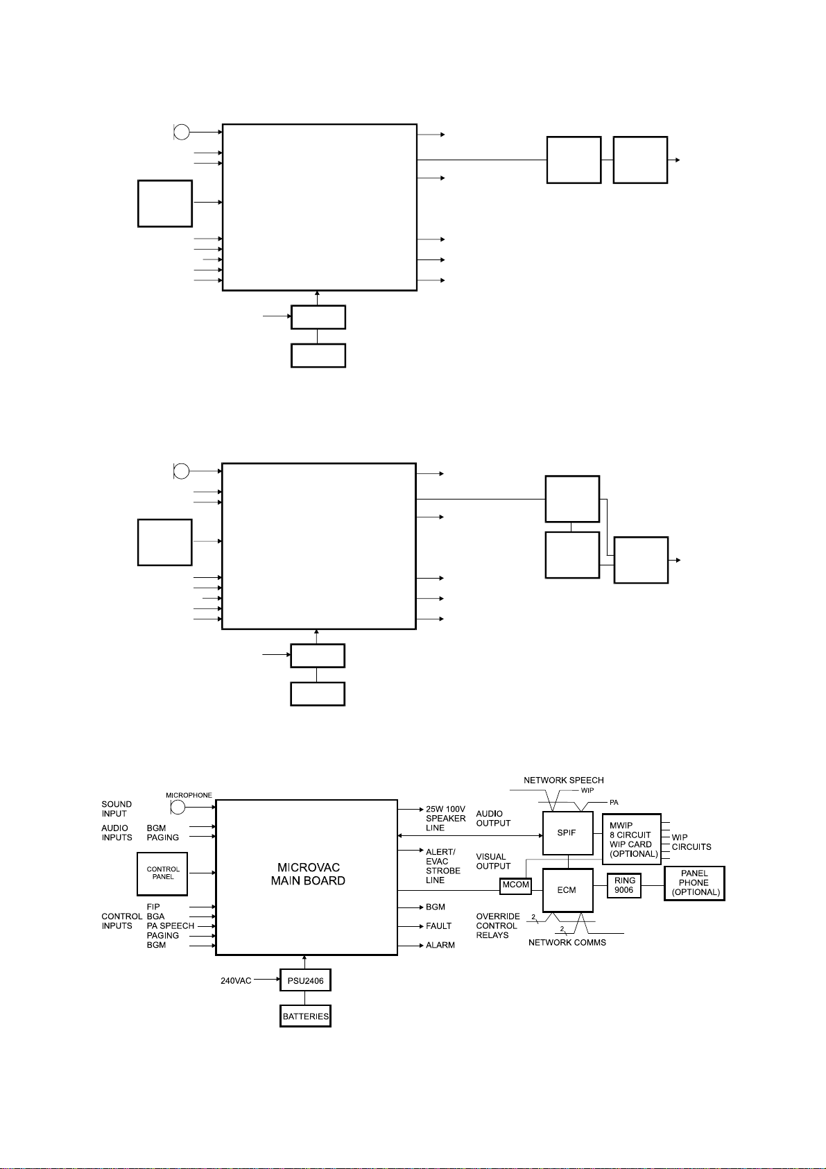
1.2 SYSTEM CONCEPT ...............................................................................................1-2
1.2.1 OPERATOR FUNCTIONS................................................................................1-4
1.2.2 EMERGENCY WARNING AND AUXILIARY FUNCTIONS...............................1-4
1.2.3 POWER SUPPLY.............................................................................................1-4
1.3 SPECIFICATIONS...................................................................................................1-5
1.3.1 GENERAL........................................................................................................1-5
1.3.2 CABINET..........................................................................................................1-6
1.3.3 INPUTS & OUTPUTS.......................................................................................1-7
1.3.4 AMPLIFIER CHARACTERISTICS....................................................................1-8
CHAPTER 2 INSTALLATION, WIRING, SETUP & COMMISSIONING. 2-1
2.1 INSTALLATION ......................................................................................................2-1
2.2 WIRING...................................................................................................................2-1
2.2.1 MAINS..............................................................................................................2-1
2.2.2 BATTERIES......................................................................................................2-1
2.2.3 AUXILIARY 24V OUTPUT................................................................................2-1
2.2.4 FAULT RELAY OUTPUT..................................................................................2-2
2.2.5 STROBE OUTPUT...........................................................................................2-2
2.2.6 BGM OVERRIDE RELAY OUTPUT..................................................................2-3
2.2.7 ALARM RELAY OUTPUT.................................................................................2-3
2.2.8 FIP AND BGA INPUTS.....................................................................................2-4
2.2.9 PAGING CONTROL INPUT..............................................................................2-5
2.2.10 BGM / AFTER HOURS CONTROL INPUT.......................................................2-5
2.2.11 BGM, PAGING AND AUX AUDIO INPUTS.......................................................2-6
2.2.12 100V SPEAKER LINE ......................................................................................2-6
2.2.13 EXTERNAL DC POWER INPUT.......................................................................2-7
2.2.14 VIGILANT HIGH POWER AMPLIFIER WIRING...............................................2-8
2.2.15 THIRD PARTY BOOSTER AMPLIFIER WIRING..............................................2-8
2.2.16 NETWORK WIRING.......................................................................................2-10
2.2.17 MASTER WIP WIRING...................................................................................2-10
2.2.18 FIELD WIP WIRING .......................................................................................2-10
2.3 SETUP - DIP SWITCH SETTINGS........................................................................2-11
2.3.1 NETWORKED MODE.....................................................................................2-11
2.3.2 ALERT TO EVACUATE DELAY (NON NETWORKED MODE).......................2-11
2.3.3 INITIAL DELAY BEFORE ALERT (NON NETWORKED MODE)....................2-11
2.3.4 PTT / PA MODE .............................................................................................2-12
2.3.5 FIP / BGA SHORT CIRCUIT FAULT MONITORING.......................................2-12
2.3.6 25W OR 100W/200W .....................................................................................2-12
2.3.7 NUMBER OF EVACUATE MESSAGES.........................................................2-12
2.3.8 NUMBER OF ALERT MESSAGES.................................................................2-12
2.3.9 USE OF BGM CONTROL INPUT : BGM OR AFTER-HOURS........................2-12
2.3.10 DISABLE MAINS AND CHARGER FAULT MONITORING.............................2-13
2.3.11 SPEECH IN MANUAL MODE.........................................................................2-13
2.4 COMMISSIONING.................................................................................................2-13
2.4.1 POWERING UP..............................................................................................2-13

Vigilant MICROVAC Owner's Manual Document: LT0109
Page iv 5 April 2000 Issue 1.31
2.4.2 CHECKING AND ADJUSTING THE CHARGER VOLTAGE...........................2-13
2.4.3 TESTING THE OUTPUTS & ADJUSTING THE LEVEL CONTROLS.............2-14
2.4.4 CHECKING THE FIP INPUT ..........................................................................2-14
2.4.5 CHECKING THE BGA INPUT ........................................................................2-14
2.5 WIRING DIAGRAMS.............................................................................................2-15
CHAPTER 3 OPERATION....................................................................... 3-1
3.1 CONTROLS ............................................................................................................3-1
3.1.1 AUTOMATIC - MANUAL - ISOLATE KEYSWITCH...........................................3-1
3.1.2 PA PUSHBUTTON...........................................................................................3-1
3.1.3 EVACUATE PUSHBUTTON.............................................................................3-1
3.1.4 ALERT PUSHBUTTON ....................................................................................3-2
3.1.5 LAMP TEST PUSHBUTTON............................................................................3-2
3.1.6 SILENCE PUSHBUTTON.................................................................................3-2
3.2 FRONT PANEL FAULT/ALARM INDICATORS......................................................3-2
3.3 STATUS INDICATORS...........................................................................................3-3
3.4 INTERNAL FAULT DISPLAY & MUTE SWITCH ....................................................3-4
3.5 NETWORKED MICROVAC WIP OPERATION .......................................................3-5
CHAPTER 4 APPENDIX.......................................................................... 4-1
4.1 GLOSSARY ............................................................................................................4-1
4.2 COMPATIBLE EQUIPMENT...................................................................................4-1
4.3 BATTERY CALCULATIONS...................................................................................4-2
AMENDMENT LOG
Date Issue Description
17 August 1992 Issue 1 Original
16 November 1992 Issue 1.1 Added 2.2.13 External DC Power Input
Added Wiring/Setup Diagram
18 April 1995 Issue 1.2 Added Booster Amplifier Wiring, external Power Supply
details
1 June 1999 Issue 1.3 Modified High Power Amplifier wiring, added
networking.
05 April 2000 Issue 1.31 Cabinet dimensions updated (pages 1-1, 1-6).
Networked wiring diagrams added (pages 2-14, 15,
16). Section 0 re-issued.

Document: LT0109 Vigilant MICROVAC Owner's Manual
System Description and Specification
Issue 1.31 5 April 2000 Page 1-1
CHAPTER 1 SYSTEM DESCRIPTION & SPECIFICATION
1.1 OVERVIEW
The Vigilant MICROVAC is a self-contained single zone emergency warning system
designed to facilitate the orderly evacuation of a zone in the event of an emergency.
Microprocessor-based, MICROVAC has been designed to perform the functions specified by
Australian Standard AS2220.1 (1989) for emergency warning systems in buildings. When
used in a standalone mode it contains no facilities for the emergency intercommunication
system requirements of AS2220. These are an option in networked systems.
The MICROVAC emergency warning system generates the emission of audible warning
signals throughout the zone via loudspeakers. In areas where the background noise level is
high, the loudspeakers can be supplemented by the use of visible warning strobe lights.
Two standard 25W versions are available, wall mounting (FP0530), and rack mounting
(FP0533). The rack mounting version is designed for integration within a Fire Panel, and to
use the Fire Panel's power supply.
In addition models are available with integrated 100W or 200W booster amplifiers.
All models may be supplied with or without networking facilities. Networking enables a
Microvac to be integrated with a QE90 system and controlled by one or more QE90 ECPs.
The product line-up and part numbers are given below.
Networked Power Mounting Part
Number Size
H*W*D (mm)
No 25W Wall FP0530 555*380*125
No 25W Rack FP0533 133*483*275
No 100W (1.5A PSU) Wall FP0626 440*550*211
No 100W (6A PSU) Wall FP0598 440*550*211
No 200W (6A PSU) Wall FP0599 750*550*211
Yes 25W (1.5A PSU) Wall FP0762 750*550*222
Yes 100W (6A PSU) Wall FP0763 750*550*222
Yes 200W (6A PSU) Wall FP0764 885*575*380
WIP facilities can be added to the networked versions in two ways (separately or combined).
Firstly a single WIP can be connected to the ECM module and used as a WIP for that zone.
Picking up this WIP will automatically call the programmed ECPs in the system. The WIP
may be called from these ECPs.
Secondly an 8 circuit WIP module (or more depending on the cabinet size) may be installed
in the Microvac to provide up to 8 field WIPs. In addition a WIP connected to the ECM
module may be used as a Master WIP. All these WIPs may be called from designated ECPs
in the network, and may call to these ECPs. Calls from the field WIPs may in addition be
answered by the Microvac master WIP. However as there are no WIP controls at the
Microvac it is not possible to call the field WIPs from the Microvac master WIP.
Table of contents
Other Vigilant Fire Alarm manuals
Popular Fire Alarm manuals by other brands

Simplex
Simplex 4010ES Quick reference guide

Global Fire Equipment
Global Fire Equipment VALKYRIE AS manual

Zeta Alarm Systems
Zeta Alarm Systems INFINITY ID2 installation manual

System Sensor
System Sensor 22051TLE-RF-26 Installation and maintenance instructions

Pittway
Pittway Notifier AM2020 troubleshooting guide

Ampac
Ampac ZoneSense user manual

Radionics
Radionics Radionics 9124 user guide

UniPOS
UniPOS FD 7120 instruction manual

Teletek electronics
Teletek electronics SensoMAG MRB50 installation instructions

bolid
bolid S2000-IP-03 instruction manual

FIREGUARD GLOBAL
FIREGUARD GLOBAL FG-S01_AP quick start guide

Panasonic
Panasonic MEW01091 operating instructions