INTERNAL WIRING
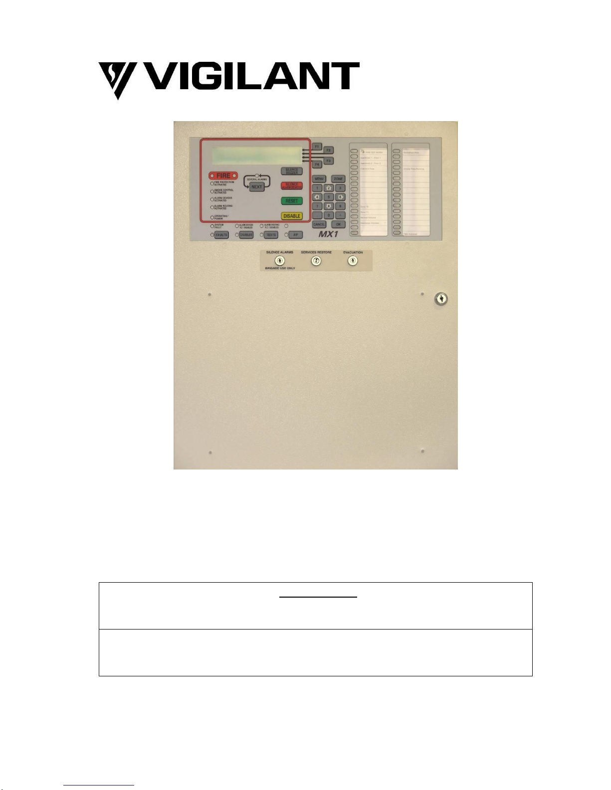
T-Gen2
These instructions describe a basic installation of
a T-Gen2 tone generator on the left hand side of
an MX1 15U gearplate (T-Gen 60 or the T-Gen
120) or the MX1 slimline gearplate (only the
T-Gen 60) and wiring it to the usual ANC1
terminals.
Refer to LT0667 T-Gen2 Installation and
Operating Instructions and LT0442 MX1 Wiring
Diagrams for installations involving:
Mounting in other positions on the 15U or BTO
gearplates.
Mounting and use of the 3U T-Gen2 User
Interface door.
Mounting and use of the 100V Splitter or 100V
Switcher modules.
Use of slave T-Gen2 units.
Connection of paging consoles.
Configuring the T-Gen2 to use non-default
operation.
The T-Gen 60 mounts onto the MX1 gear plate in
the ‘responder footprint’ position, which has five
holes for plastic standoffs and one metal
standoff.
The T-Gen 120 mounts onto the 15U MX1 gear
plate in the ‘responder footprint’ position, but is
fixed in place using four M4 screws and the MX
Loop card mounting holes.
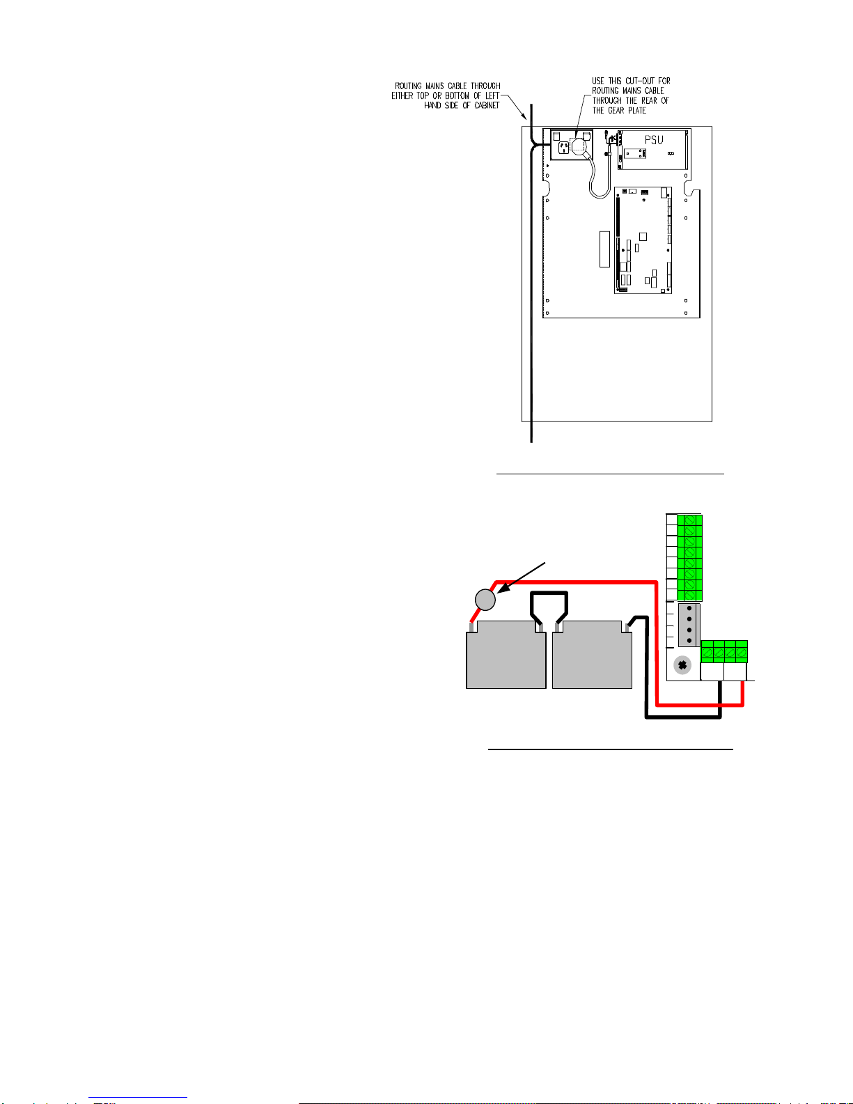
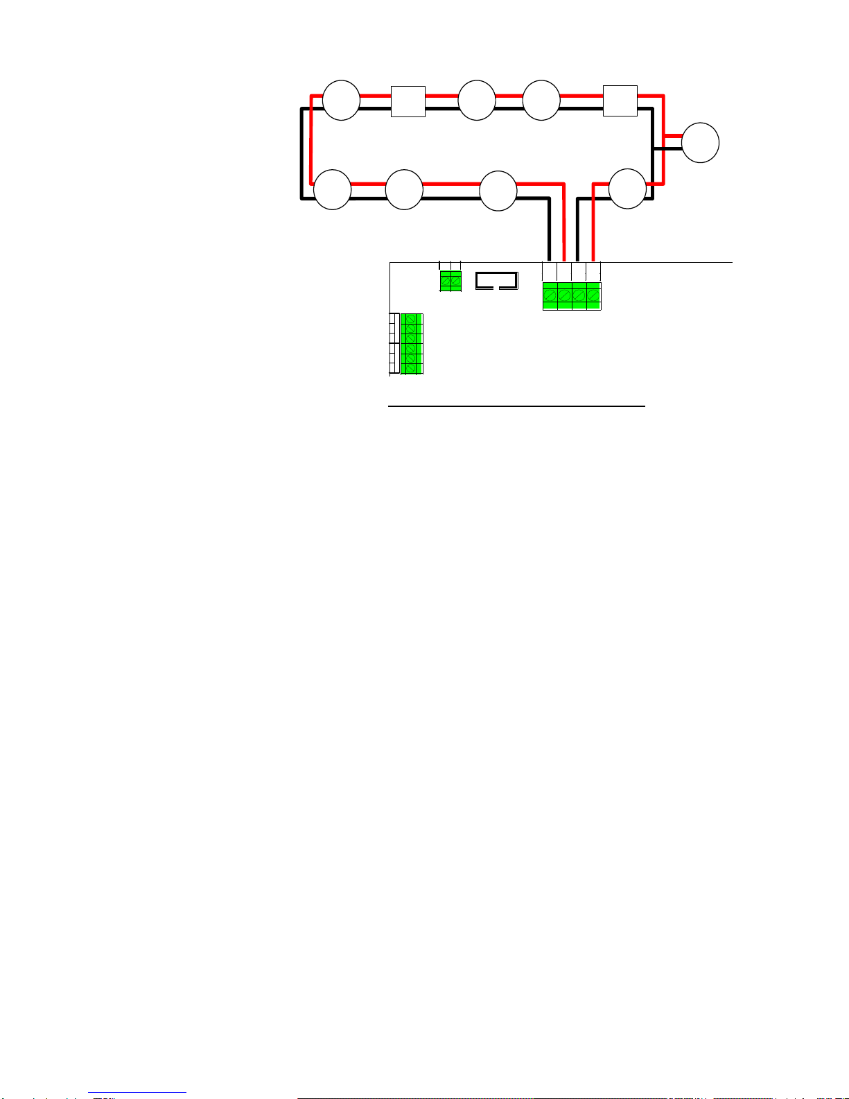
The T-Gen2 can be connected to the ANC1 relay
output as shown in Figure 7a, with power wiring
modifications, as shown, to the pre-made loom
(LM0319) included for this purpose. The loom
plugs in to the 6 way header on ANC1 (remove
the red +VBF and black 0V wires if present). The
T-Gen2 takes its power from the MX1 Loop
Interface Supply Terminal (J33) through a 10A
fuse. Use the LM0459 and fuse provided with the
T-Gen2.
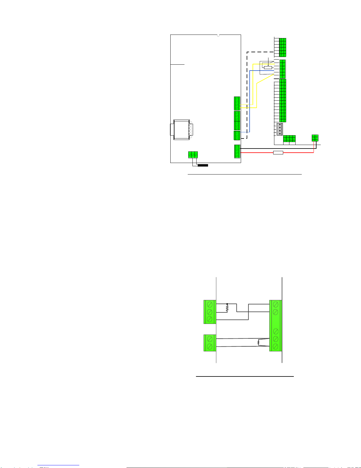
This wiring provides complete supervision of
wiring open and short circuits, as well as passing
the state of the T-Gen2’s fault relay to the MX1
controller.
The 10kresistor is critical to this supervision
and should not be omitted, or a different value
substituted.
ANC2 could be used to control the T-Gen2
instead of ANC1, but this will require manual
wiring as the supplied loom supports only ANC1.
The MX1 must be configured to have “Contact”
supervision enabled for whichever ANC 1 or 2
output is being used.
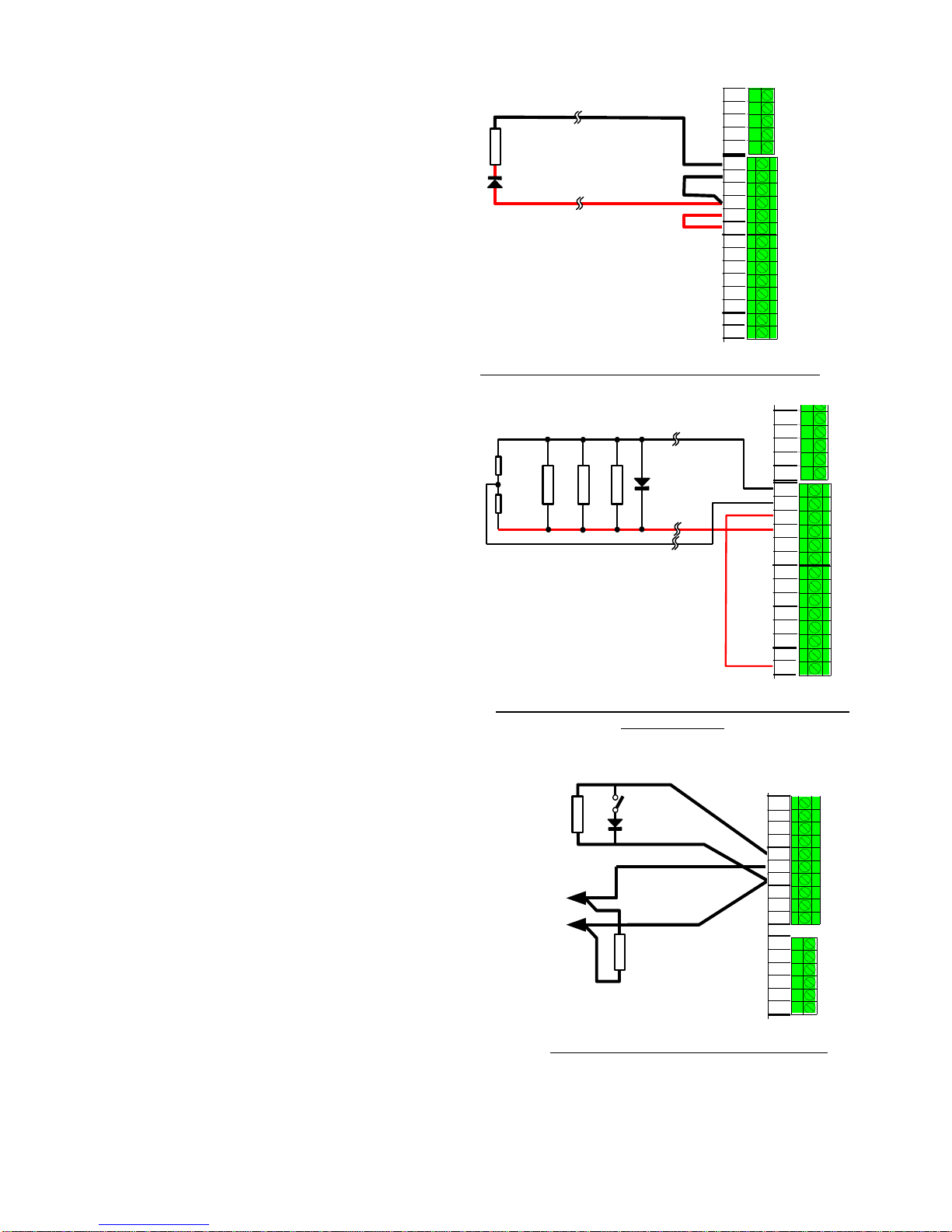
Figure 7a –Wiring Ancillary Relay 1 to T-Gen2
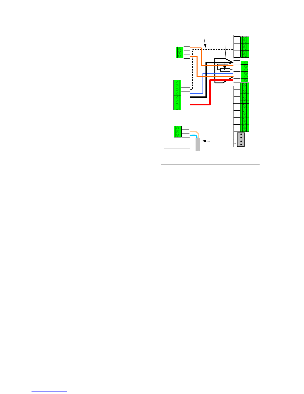
When the T-Gen2 Alert tone must be controlled by the MX1,
one of the GP OUT terminals can be connected to the T-
Gen2’s A/I/E- input, as shown in the diagram. This is not
default operation, and the MX1 must be specially configured.
T-Gen2 must be programmed to use the AS2220
configuration (refer to LT0667 for details on how to do this).
The default configuration means that once the T-Gen2 is
wired, it is ready for operation without further programming.
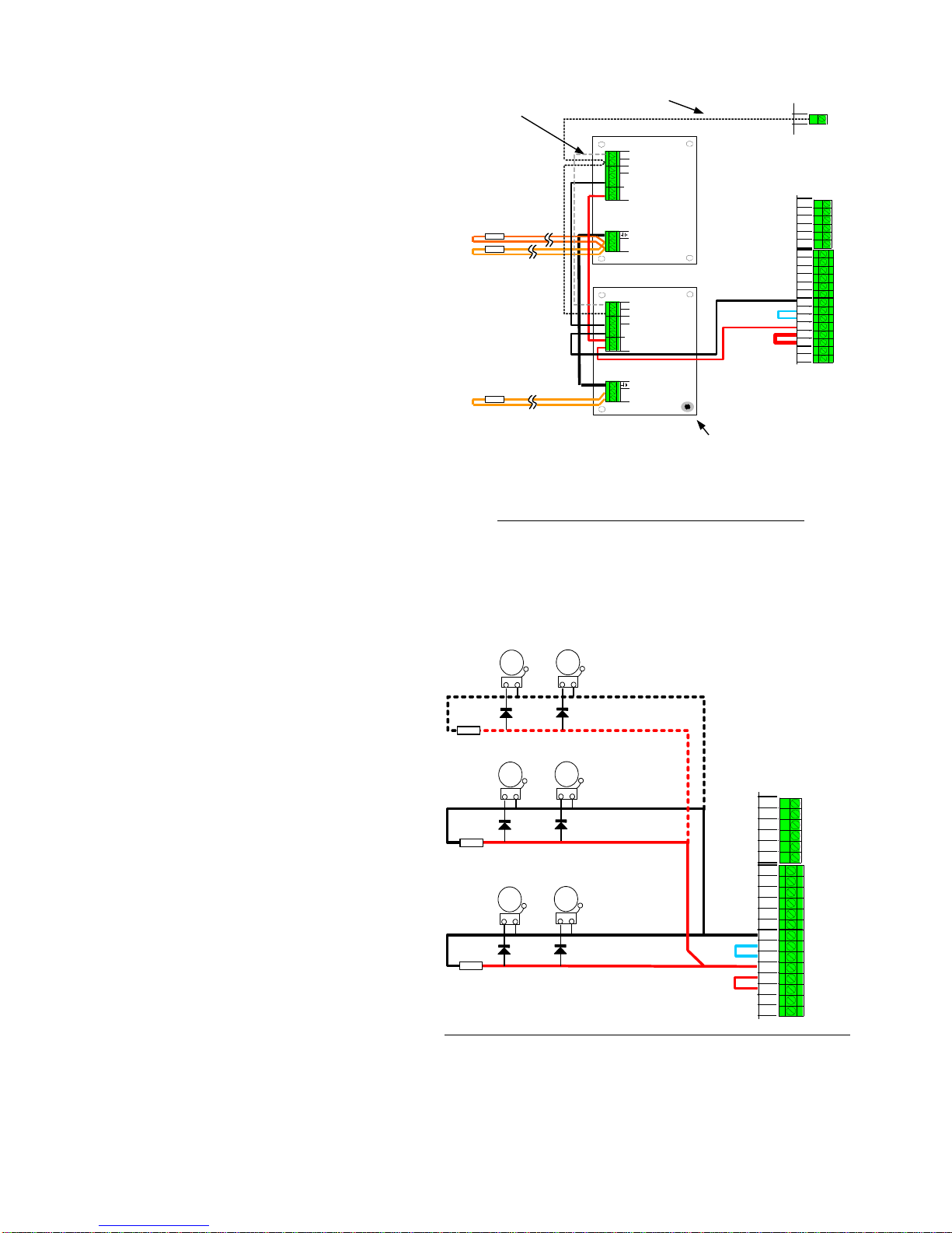
A T-Gen2 can be controlled by the MX1 ANC3 relay, using the
wiring shown in Figure 7b. ANC3 supervision is set to “ANC3”.