Vigilant LT0554 User manual

Building Occupant
Warning Systems (BOWS)
Installation & Operation
Manual
LT0554
Issue 1.20

Vigilant BOWS Installation & Operation Manual Document: LT0554
Page 6 September 2012 Issue 1.20
ii
THIS PAGE INTENTIONALLY LEFT BLANK

Document: LT0554 Vigilant BOWS Installation & Operation Manual
Issue 1.20 6 September 2012 Page iii
Table of Contents
Chapter 1 Introduction........................................................................1-1
Chapter 2 Operation............................................................................2-1
Chapter 3 Configuration.....................................................................3-1
Chapter 4 Installation & Wiring..........................................................4-1
Chapter 5 Diagnostics ........................................................................5-1
Chapter 6 Specifications ....................................................................6-1

Vigilant BOWS Installation & Operation Manual Document: LT0554
Page 6 September 2012 Issue 1.20
iv
THIS PAGE INTENTIONALLY LEFT BLANK

Document: LT0554 Vigilant BOWS Installation & Operation Manual
Issue 1.20 6 September 2012 Page 1-1
The VIGILANT Building Occupant Warning System (BOWS) is a self-
contained AS 2220 or ISO 8201 Alert and Evacuate tone generator, with
integral power supply, speaker line supervision, digitised speech
messages and PA microphone. It has been designed to connect directly
to a fire alarm panel, but can be alternatively used stand-alone.
A block diagram of the BOWS is shown in Figure 1.
Figure 1. BOWS Block Diagram
The BOWS has a microphone for emergency public address, fault and
status indicators, and an Evacuation Control key switch to select its
operating mode. It has audio inputs for background music, remote audio
(which can be used when streaming audio over IP networks), and non-
emergency paging (zone-selective with an add-on option).
The BOWS has a 24V 5A power supply / battery charger compatible with
17Ah batteries.
Chapter 1
Introduction
Introduction
EOL
T-GEN 50
Alert and
Evacuate tone
generator
24V 5A Power Supply
BOWS
Interface
Board
Batteries
(typically 2 x 12V 17Ah)
2 x 12V 6.5Ah, 12Ah or
17Ah
Emergency
PA Mic
100V Speaker
Line
Alarm (& fault back)
Remote Audio
Background Music
EOL
Paging (optional)

Vigilant BOWS Installation & Operation Manual Document: LT0554
Page 6 September 2012 Issue 1.20
1-2
The VIGILANT BOWS is available in two standard configurations:
FP1021 single 50W audio output.
FP1022 single 100W audio output.
Figure 2. Figure 3.
1 x 50W output (FP1021) 1 x 100W output (FP1022)
The FP1021 50W BOWS may be upgraded in the field by adding a
second T-GEN 50 to provide a second 50W output.
The FP1022 is fitted with a master T-GEN 50 and a slave T-GEN 50, with
the outputs arranged in a bridge configuration to provide a single 100W
output.
Note: it is not possible to convert a FP1021 50W BOWS to an FP1022
100W BOWS in the field.
The BOWS can optionally be fitted with a speaker distribution module
(SDM-4) which allows the single 100V 50W/100W output to be split into
four separately selectable 100V line outputs. Each output has separate
line supervision (o/c & s/c). The SDM-4 will isolate a shorted output
allowing the other outputs to operate. Each output is rated at 40W max.
The total load cannot exceed the BOWS rating (50W or 100W).
50W or
100W
SDM-4
100V Out 1
100V In
100V Out 2
100V Out 3
T-GEN Speaker Line/Zone 1
Speaker Line/Zone 2
Speaker Line/Zone 3
Speaker Line/Zone 4
EOLR
EOLR
EOLR
EOLR
BOWS
100V Out 4
Figure 4. BOWS fitted with an SDM-4 Speaker Distribution Module
The SDM-4 is included with the optional paging kits to provide up to 4
selectable paging zones.
BOWS
T-GEN
50W
BOWS
T-GEN
T-GEN
100W

Document: LT0554 Vigilant BOWS Installation & Operation Manual
Issue 1.20 6 September 2012 Page 1-3
Figure 5.
A4485 Paging
Console
Figure 6.
BOWS fitted with the
Zone Select switch
The BOWS supports zone selectable paging using the A4485 4-Zone
Paging Console (see Figure 5).
For this paging option the FP1023 BOWS ZONE PAGING KIT is
required.
This kit includes the following items:
-SDM-4 Speaker Distribution Module
-SDM-4 mounting bracket & screws
-A4485 4 zone paging console
-Connectors and wire (excluding CAT5 cable)
-BOWS Zone Paging Kit Installation Guide (LT0558)
It addition to the FP1023 kit you will also require a suitable
length of standard CAT5 (Ethernet) cable terminated with
RJ45 connectors for connecting the paging console to
the BOWS. This cable can be up to 300m in length.
Refer to the BOWS Zone Paging Kit Installation Guide
(LT0558) supplied with the kit for further details.
The BOWS supports zone selectable paging using the Emergency PA
Microphone.
For this paging option the FP1024
EMERGENCY MIC ZONE PAGING KIT is
required.
This kit includes all the required parts
including:
-SDM-4 Speaker Distribution Module
-SDM-4 mounting bracket & screws
-Zone selector switch
-Panel label
-Connectors and wire
-BOWS Zone Paging Kit Installation
Guide (LT0558)
Note that the zone selector switch and label are mounted on the
3U blank panel of the BOWS (see Figure 6) and two holes (4mm
& 10mm dia) must be drilled in this panel by the installer to mount
the switch.
Refer to the BOWS Zone Paging Kit Installation Guide (LT0558)
supplied with the kit for further details.
Zone Paging
Console
Zone Paging
Using the
Emergency PA
Mic

Vigilant BOWS Installation & Operation Manual Document: LT0554
Page 6 September 2012 Issue 1.20
1-4
THIS PAGE INTENTIONALLY LEFT BLANK

Document: LT0554 Vigilant BOWS Installation & Operation Manual
Issue 1.20 6 September 2012 Page 2-1
The BOWS has 5 front panel indicators (LEDs) and an Evacuation
Control key switch (003) located on the inner front door (Figure 7), plus
an emergency PA microphone with its press-to-talk (PTT) switch.
Figure 7. Inner Door Controls and Indicators
The BOWS has 5 indicators on the front panel as shown in Table 1.
Table 1. BOWS Front Panel Indicators
Indicator
Colour
Description
Power On
Green
On when power is on
Alarm
Red
Alarm input (ALM-) is activated by the
fire alarm system
Isolated
Blue
Evacuation Control switch is in the
ISOLATE position
Audio Fault
Yellow
100V speaker line is open or short circuit
or
amplifier fault
Power Supply
Fault
Yellow
Power supply is in fault (e.g., battery
charge low or disconnected)
Chapter 2
Operation
Summary
Indicators

Vigilant BOWS Installation & Operation Manual Document: LT0554
Page 6 September 2012 Issue 1.20
2-2
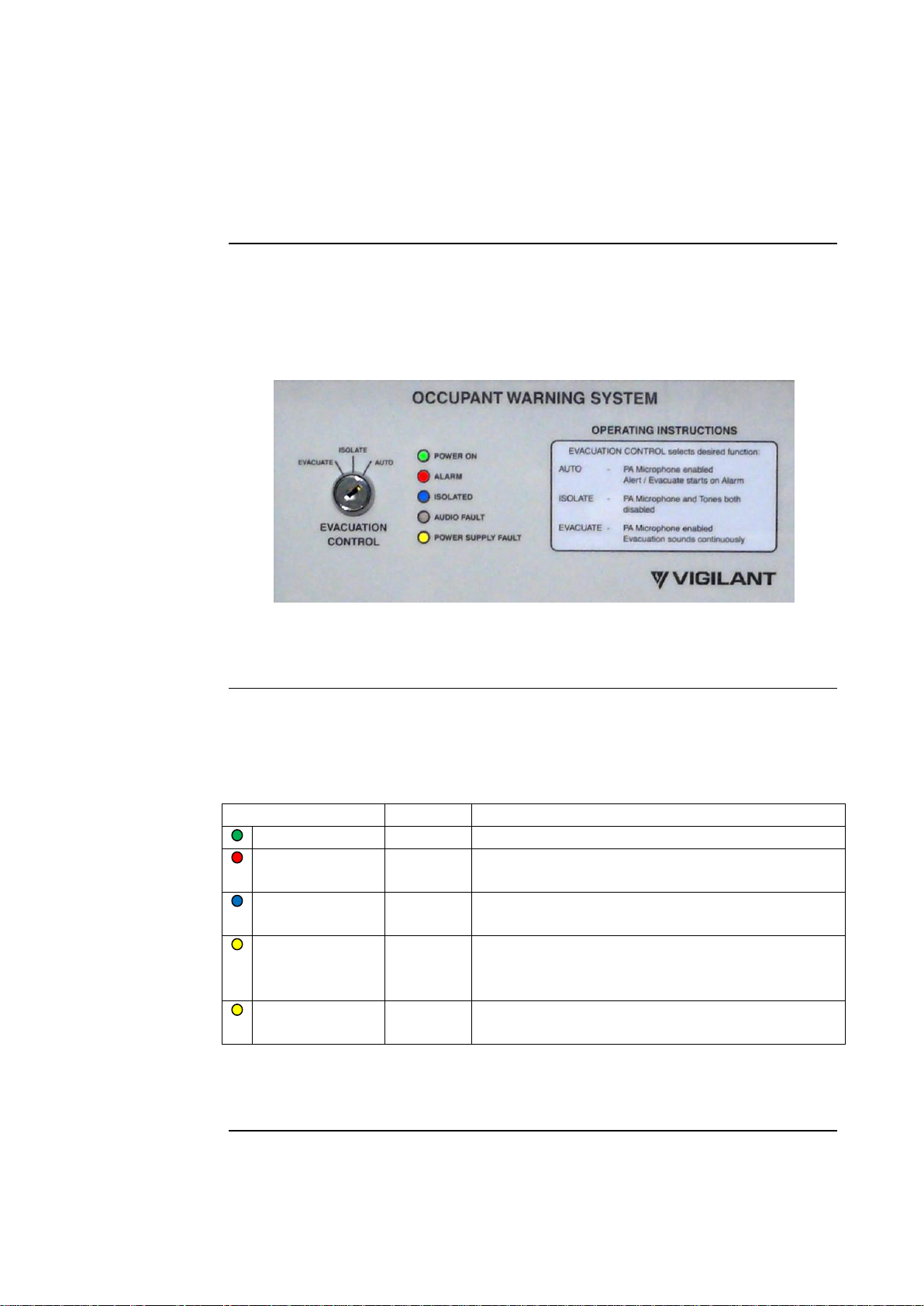
Operation of the BOWS is controlled by the Evacuation Control 003 key
switch. In the “AUTO” position the Alarm input (ALM-) is enabled. In the
“ISOLATE” position the Alarm input is disabled and any latched fault or
alarm conditions are reset. In the “EVACUATE” position the Evacuate
tone is generated.
In Auto mode activation of the Alarm (ALM-) input starts a six-stage rising
amplitude Alert tone. This continues until one of the following occurs:
-the Alarm input returns to normal (Alarm input in non-latching mode),
or
-the Evacuation Control switch is changed to Isolate, or
-the Evacuation Control switch is changed to Evacuate, or
-the Alert to Evacuate change-over time is reached.
If the Alert to Evacuate change-over time is set to 0 sec, then no Alert
tone is generated and the Evacuate tone is generated immediately. If the
change-over time is set to Alert only, no Evacuate tone is generated and
must be initiated manually. Alert and Evacuate voice messages are
automatically inserted in the Alert and Evacuate tone sequences
respectively. Messages shorter than 0.5 seconds are not inserted.
Generally with the Evacuation Control switch in the “AUTO” position the
operation of the BOWS is controlled via the ALM- input from the fire
panel.
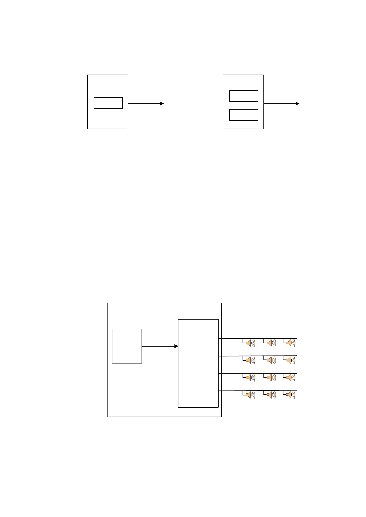
A test mode is provided for testing the 100V line and speakers. To
activate this put the BOWS into Auto and fit the Test Link (LK4) on the
(master) T-GEN 50. The BOWS will produce a short 500Hz tone burst
every 4 seconds at low volume (-30dB).
If the 100V line is overloaded (e.g. short circuit), the BOWS will shut
down its amplifier output until the fault is removed. Detection of an open
or short circuit on the 100V line output will also cause a fault condition.
If the Alarm input fault supervision is enabled, an open circuit on the
ALM- input will cause a fault condition.
These fault conditions will turn on the Audio Fault indicator and activate
the Fault output. Note that the 100V line is not supervised for the first 60
seconds after power up to allow the monitoring capacitors to charge up.
Note that the BOWS fault outputs are put into the fault state when the
BOWS Evacuation Control switch is in the “ISOLATE” position.
Evacuation
Control Switch
Test Mode
Fault
Monitoring

Document: LT0554 Vigilant BOWS Installation & Operation Manual
Issue 1.20 6 September 2012 Page 2-3
The BOWS contains four digitised speech messages, defined as Msg1,
Msg2, Alert and ISO 8201 keywords. Refer to the Recorded Message
table in the Configuration section for the actual pre-recorded phrases.
The BOWS will play the alert message during alert, Msg1 (or Msg1 +
Msg2 if recording is longer than 4 seconds) during AS 2220 or ISO 8201
Evac if SW8 is off, Msg2 during AS 2220 if SW8 is on, and just the
ISO 8201 keywords during ISO8 201 if SW8 is on.
The operator may use the PA microphone for emergency public address.
This is activated when the microphone‟s PTT button is pressed while the
Evacuation Control switch is in either the AUTO or EVACUATE position.
Emergency PA overrides the Alert and Evacuate tones.
The BOWS supports remote paging using the A4485 4 zone paging
console (Figure 8).
To use this feature the FP1023 BOWS ZONE PAGING KIT option
(includes an SDM-4 and Paging Console) must have been installed.
The A4485 paging console has the following controls and indicators
(Figure 8):
Talk switch Off Microphone is turned off
Page Microphone is turned on (turns off when
released)
Lock On Microphone is turned on
Zone Select switches Push to select / deselect a zone
A blue indicator on the button is turned on
when the zone is selected
All Call Selects all 4 zones
Cancel Deselects all zones
Busy (indicator) Turned on if the console is not ready for
paging
Operation
Select the zone or zones to be paged using the zone select buttons
on the paging console.
Move the talk switch on the console forward to the Page position.
Make the announcement and then release the talk switch.
Paging can be configured to override, or not override, the Alert/Evacuate
tones. If configured to not override tones the paging will operate only
when the BOWS is not in Alarm and the Evacuation Control switch is in
the AUTO position (e.g. not generating tones).
If configured to override tones the paging will also operate when the
BOWS is in Alarm or the Evacuation Control switch is in the EVAC
position (e.g. generating tones). In this mode the paging console will
operate in a similar manner to the emergency PA microphone and
announcements will be automatically broadcast to all zones overriding
Evacuation
Messages
Public Address
Paging Using
the Paging
Console

Vigilant BOWS Installation & Operation Manual Document: LT0554
Page 6 September 2012 Issue 1.20
2-4
the tones. Note that the operator must still select at least one zone on the
paging console to activate the microphone.
The A4485 paging console has a pre-announcement chime option that
can be selected via a DIP switch located at the rear of the console. Refer
to the A4485 Paging Microphone Operating Instructions supplied with the
console for further details.
The BOWS supports selectable paging of up to 4 zones using the BOWS
emergency PA microphone.
To use this feature the FP1024 BOWS EMERGENCY MIC ZONE
PAGING KIT option (includes an SDM-4) must have been installed.
Operation:
Select the zone to be paged using the PAGING ZONE SELECT
switch (Figure 9).
Make the announcement using the BOWS Emergency PA
microphone by pushing the microphone‟s push to talk button.
Zone-by-zone paging is available only when the BOWS is not in
Alarm and the Evacuation Control switch is in the AUTO position. If the
Emergency PA microphone is used when the BOWS is generating tones
the PA announcements will be broadcast to all zones, irrespective of the
Paging Zone Select switch position.
Paging Using
the PA
Microphone
Figure 8.
Paging Console
Figure 9.
Zone Selector Switch

Document: LT0554 Vigilant BOWS Installation & Operation Manual
Issue 1.20 6 September 2012 Page 2-5
The BOWS has a 3.5mm audio jack and screw terminals for connecting
an external background music audio source to the BOWS. The
background music will play whenever the Evacuation Control switch is in
the AUTO position, the BOWS is not generating tones, and no other
audio source (such as the emergency PA microphone or paging console)
is being used.
The BOWS has a 3.5mm audio jack and screw terminals for connecting
an external remote audio source to the BOWS. The remote audio input
has an Active input signal, which must be activated by the external audio
source to broadcast the audio. The remote audio input can be configured
to either override the T-GEN tones (similar to the emergency PA
microphone) or not override tones (similar to the background music
input). This input has been designed to be compatible with the BARIX
range of audio-over-IP devices. Refer to the IP Networking Using Barix
Modules section later in this manual.
Background
Music
Remote Audio

Vigilant BOWS Installation & Operation Manual Document: LT0554
Page 6 September 2012 Issue 1.20
2-6
THIS PAGE INTENTIONALLY LEFT BLANK

Document: LT0554 Vigilant BOWS Installation & Operation Manual
Issue 1.20 6 September 2012 Page 3-1
The operation of the BOWS is configured via links on the BOWS
Interface board and an 8-way DIP switch and links on the (Master)
T-GEN 50.
Figure 10. View inside 50W BOWS cabinet
Chapter 3
Configuration
Summary
Power
Supply
T-GEN 50
(master)
BOWS
Interface
Board
T-GEN 50
(slave)
mounted
here when
fitted

Vigilant BOWS Installation & Operation Manual Document: LT0554
Page 6 September 2012 Issue 1.20
3-2
The BOWS Interface board has 5 links to configure the priority of the
Paging, Remote Audio, and Emergency Mic audio inputs, plus volume
(level) controls for background music, paging, and remote audio. The
Issue B boards also have an ACTIVE LOW link.
Figure 11. BOWS Interface Board
Each of the 3 audio sources (Paging, Remote Audio, Emergency Mic)
must be configured with a priority level of HI, MED or LOW. When 2 or
more audio sources are selected at the same time this priority
determines which source will be played.
The valid combinations are shown in Table 2.
Table 2. BOWS Interface Priority Links
LK1 Paging
LK2 Remote Audio
LK3 Emergency Mic
Comment
LOW
MED
HI
Factory default
LOW
HI
MED
MED
HI
LOW
MED
LOW
HI
HI
MED
LOW
HI
LOW
MED
HI
LOW or MED
HI
Emergency PA Mic
used for paging
If any other (invalid) combinations are selected the BOWS will double
flash its Audio Fault LED every 2 seconds, activate its Fault outputs, and
use the factory default setting.
BOWS
Interface
Board
Priority Links
Issue A
ACTIVE LOW
Link
Issue B
Priority
Links
Override
Tones
Links
Volume
Controls

Document: LT0554 Vigilant BOWS Installation & Operation Manual
Issue 1.20 6 September 2012 Page 3-3
The Paging and Remote Audio sources each have an additional link as
per Table 3 to determine if the audio source is to override the
Alert/Evacuate tones or not.
Table 3. BOWS Interface Override Tones Links
Link
Audio Source
Link Position
Operation
LK4
Paging
No
Tones override paging audio (Factory default)
Yes
Paging overrides tones
LK5
Remote Audio
No
Tones override remote audio (Factory default)
Yes
Remote audio overrides tones
Note that the Emergency PA Mic always overrides Alert/Evacuation
tones.
The Issue B boards also include an ACTIVE LOW link. This is used to
configure the ACTIVE input on the Remote Audio port as per Table 4. If
the ACTIVE input is open (not used) it will be inactive in either link
position. Table 4. Remote Audio ACTIVE LOW Link
Link
Audio Source
Link Position
ACTIVE Input Operation
LK6
Remote Audio
No
-30V to +2V Inactive, +2V to +30V Active
(Factory default)
Yes
-30V to +1V Active, +1V to +30V Inactive
Note that on Issue A boards the ACTIVE input is always active High.
The BOWS Interface board has the following 3 volume adjustment
controls as listed in Table 5.
Table 5. BOWS Interface Volume Controls
Control
Name
Function
VR1
BM VOL
Background Music volume control.
VR2
RA VOL
Remote Audio volume control.
VR3
PC VOL
Paging Console volume control.
Note that the volume of the Emergency PA Mic is set by VR3 PA VOL on
the (master) T-GEN 50.
When an audio source is configured to „Override Tones‟ the audio source
is fed into the T-GEN PA Mic input, and therefore the output level will be
determined by both the volume control on the BOWS Interface board and
the PA VOL (VR3) on the master T-GEN 50. It is therefore recommended
to set the master T-GEN Emergency PA Mic level (VR3) first (if required)
before adjusting the volume controls on the BOWS Interface board.
Override Tones
Links
ACTIVE LOW
Link
Volume
Controls

Vigilant BOWS Installation & Operation Manual Document: LT0554
Page 6 September 2012 Issue 1.20
3-4
An 8-way DIP switch (SW1) and 7 jumpers are used to configure the
operation of the T-GEN 50.
Figure 12. T-GEN 50
The T-GEN 50 has 3 level adjustment controls as shown in Table 6.
Table 6. T-GEN 50 Level Controls
Control
Name
Function
VR1
BIAS
Amplifier Bias –Factory adjust
only.
VR2
SPEECH
VOL
Volume adjustment for recorded
messages.
VR3
PA VOL
Volume adjustment for emergency
PA microphone.
Note that the BIAS (VR1) level must not be adjusted.
T-GEN 50
(Master)
Level
Controls
SW1 Configuration
Switch
LK4 Test Link
Play Button
LK3 Record
Enable Link

Document: LT0554 Vigilant BOWS Installation & Operation Manual
Issue 1.20 6 September 2012 Page 3-5
The 8-way switch on the T-GEN 50 is used to select the alert to evacuate
change-over time, Alarm input options, Evacuation tone, and Evacuation
message selection as per Table 7 below. The factory default settings are
shown as “(default)”.
Table 7. T-GEN 50 Configuration Switch Settings
Sw1 (T0)
Sw2 (T1)
Sw3 (T2)
Alert to Evacuate
Change-Over Time
Sw4 (Mon)
Alarm I/P Fault Supervision
OFF
OFF
OFF
0 sec
OFF
Disabled
ON
OFF
OFF
30 sec (default)
ON
Enabled (default)
OFF
ON
OFF
1 min
ON
ON
OFF
1.5 min
Sw5 (Lat)
Alarm I/P
OFF
OFF
ON
3 min
OFF
Non-Latching (default)
ON
OFF
ON
5 min
ON
Latching
OFF
ON
ON
10 min
ON
ON
ON
Alert Only
Sw6
(Ev0)
Sw7
(Ev1)
Evacuate Tone
Sw8 (Att)
Evacuate Message Selection
OFF
OFF
AS2220
(relative to Evac Tone)
ON
OFF
RH3
OFF
Msg1 or field recorded
OFF
ON
ISO8201 + keywords
(default)
ON
Msg2 in AS2220 or Keywords
only in ISO8201 (default)
ON
ON
Wail (LK4 not fitted)
ON
ON
Hee Haw (LK4 fitted)
Name
Recorded Message
Msg1
“Evacuate the building using the nearest fire exit”
Msg2
“Evacuate as directed” x2
Alert
“The fire alarm system has operated. Standby for further
instructions”
ISO8201 Keywords
“Emergency” “Evacuate Now”
The T-GEN 50 has 7 links for configuring options such as Master/Slave
operation as shown in Table 8, Test Tone generation and recording
messages. Generally, only the REC EN and TEST links should be
changed on the master T-GEN.
Table 8. T-GEN Link Settings
„
Link
Name
Function
1
BIAS
Amplifier bias disable. Fit link to reduce quiescent current if the BOWS is to be used with
tones only (no speech or background music). Default Position : Not Fitted
2
MASTER
Fit for master, remove for slave. Default Position : Fitted
3
REC EN
Fit to record message. Refer Recording Messages. Default Position : Not Fitted
4
TEST
Fit for test tone (500Hz pulsing on/off at -30dB). Operates in “Auto” only and excludes
Wail & Hee Haw. Default Position : Not Fitted
5
SLAVE
Fit for slave mode only. Read only on power up. Default Position : Not Fitted
6
SLAVE /
MASTER
Selects slave or master mode - fit as appropriate. Default Position : MASTER
7
FAULT=
DEF-/RELAY
Enables the operation of either the Fault Relay or the DEF- output.
Default Position : DEF-.
Configuration
Switch
Links

Vigilant BOWS Installation & Operation Manual Document: LT0554
Page 6 September 2012 Issue 1.20
3-6
The BOWS supports 2 recordable messages, Alert and Evac. Alert can
be up to 4 seconds long. Evac consists of two factory-programmed
messages (Msg1 and Msg2) that can be up to 7.2 seconds in total
length. The Alert and Evac messages can be re-recorded using the
Emergency PA microphone.
To record a message use the following steps (when the BOWS is not in
alarm or evacuate or test mode):
1. Fit link LK3 - REC EN on the T-GEN (master). This enables the
recording and playback of messages.
2. Select the message to be recorded (played) using switch 2 - T1 as
follows:
T1 Off - Evac message T1 On - Alert message
3. Press the Emergency PA microphone button to start recording.
Recording will continue until either the button is released or the
maximum message length has been reached (see NOTE).
4. The recorded message can be played back using the Play button
on the T-GEN board. Note that if the Evacuation Control switch is
not in the Isolate position the played back message will be
broadcast over the speaker system. Recording is not broadcast.
5. When recording has been completed, re-set T1 to its original
position and remove Link LK3 to disable the record function.
NOTE: Messages less than 0.5 seconds will not be broadcast (this
can be used to delete an unwanted message). Note that if
Evac Msg1 is replaced with a message of more than 4
seconds duration, Evac Msg2 will also be overwritten.
If the BOWS is fitted with a slave T-GEN 50 (e.g., 100W BOWS or 50W
BOWS fitted with a 2nd T-GEN), the switches on the slave T-GEN are not
used and should be left in the Off position. The links must be set in the
following positions (NF = Not Fitted): LK1 –NF, LK2 –NF, LK3 –NF,
LK4 –NF, LK5 –SLAVE, LK6 –SLAVE, LK7 –DEF-.
Recording
Messages
T-GEN 50
(Slave)
Table of contents
Popular Safety Equipment manuals by other brands

PREISING
PREISING PASA Series Instructions for use

Malta Dynamics
Malta Dynamics A6203 Operation and instruction manual

babcockdavis
babcockdavis BSRA Installation, operation & maintenance manual

IMMOOS
IMMOOS Fallbloc 2 operating instructions

Tractel
Tractel EN 361 Operating and maintenance instructions

B-Safety
B-Safety TOP-PROTECT instruction manual

schmersal
schmersal AZM300B-I1-ST1P2P-A Instructions for operation

Pressalit
Pressalit PLUS RT114 Mounting instruction

SAF-HOLLAND
SAF-HOLLAND G36 Fifth Wheel installation instructions

AUSTRIALPIN
AUSTRIALPIN SKYSTEEP operating instructions

Pima Electronic Systems
Pima Electronic Systems VISION user guide

Honeywell
Honeywell MILLER PERSONAL FALL LIMITER User instruction manual