Simplex 2099-9135 User manual

Addressable Manual Stations
2099-9135, -9761, -9795, -9796, & -9797
Installation Instructions
2000 Simplex Time Recorder Co., Westminster, MA 01441-0001 USA
All specifications and other information shown were current as of publication, and are subject to change without notice.
574-155
Rev. A
These instructions describe installing and setting the address for a manual
station (single action, double action, or local). Installing a manual station
consists of the following tasks:
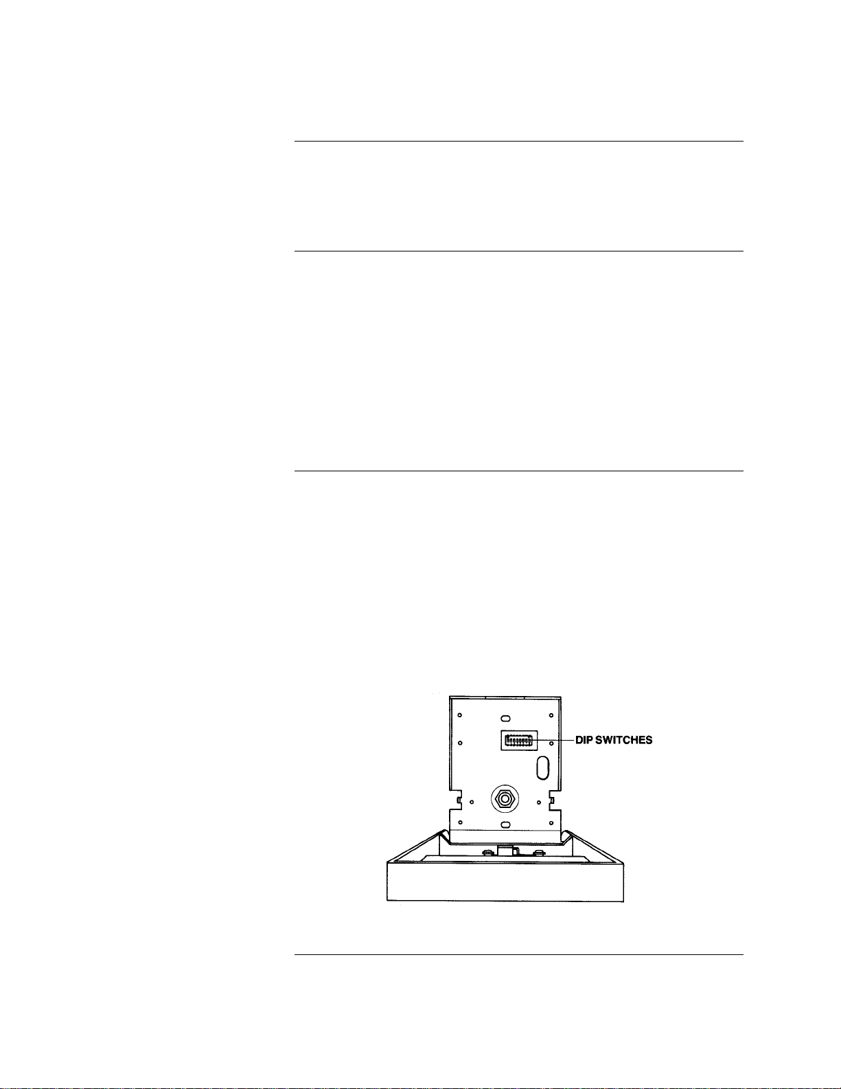
• Setting the Address. The address, which uniquely identifies the manual
station on the MAPNET IIchannel, must be set in two places the dip
switch on the rear of the manual station and through the programmer. The
address must match in both places.
• Wiring. Addressable manual stations connect to either a 2120 Multiplex
Communicating Device Transponder (CDT), 4020, 4100+, or 4120 system
by a twisted, shielded (recommended) wire pair (MAPNET), and receive
both power and data over this wire pair.
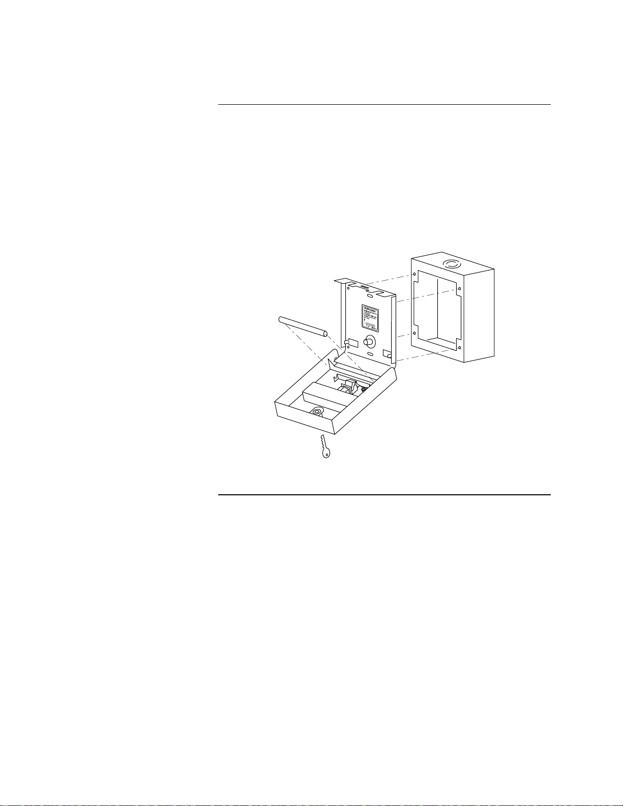
• Installing. Manual stations mount to a variety of standard switch and back
boxes.
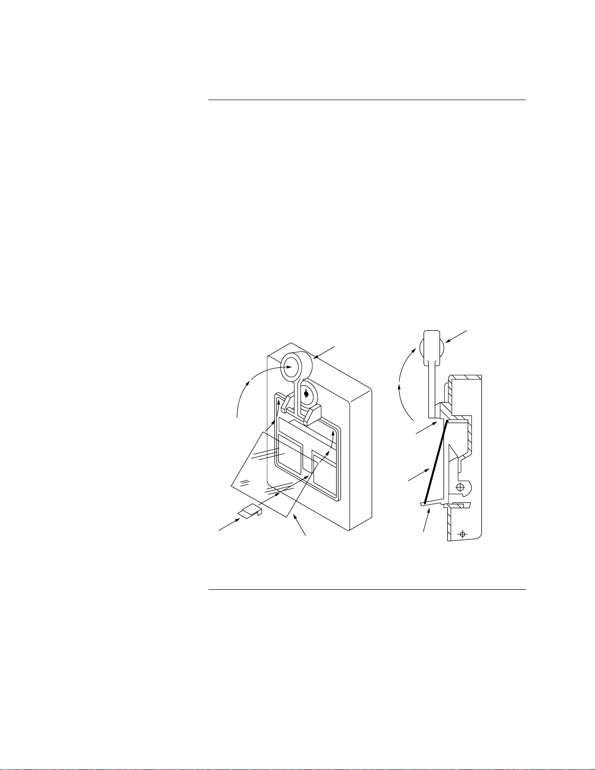
• Maintaining. Depending on the model of manual station, you may also
need to replace a small pane of glass or a glass rod following activation.
Table 1 summarizes the features of each manual station model.
PID Single
Action
Glass
Double
Action
Push
Double
Action
MAPNET
I MAPNET
IILocal
Cover
No
Simplex
Logo
2099-9135 X X X
2099-9761 X X
2099-9795 X X
2099-9796 X X
2099-9797 X X X
This publication discusses the following topics:
Topic See Page #
Setting the Manual Station’s Address 2
Wiring 4
Installing the Manual Station 5
Replacing Glass Pane/Glass Rod 6
Overview
Features
In this Publication
Technical Manuals Online! - http://www.tech-man.com
firealarmresources.com

2
Each manual station has a unique address, which is set using a series of dip
switches located inside the manual station. The manual station’s address must
match the address listed in the specification sheets of the 2120 Job
Configuration Report or the Programmer’s Report for the 4020, 4100+, or 4120
system.
1. Set the manual station’s address using Table 2. See Figure 1 for the
location of the switches. Use a small screwdriver or pen to set the switches.
When positioning each dip switch, note that 0 equals ON and 1 equals OFF.
Note: The address you set must match the address entered in the 2120 Job
Configuration Report.
2. Mark an address label with the appropriate address for the manual station.
Shade a box for each dip switch in the ON position. Leave the OFF
positions blank. Apply the label to the manual station near the dip switches.
3. Double-check the address before wiring the manual station.
1. Set the manual station’s address using Table 2. See Figure 1 for the
location of the switches. Use a small screwdriver or pen to set the switches.
When positioning each dip switch, note that 0 equals ON and 1 equals OFF.
Note: The address you set must match the address entered in the
Programmer’s Report for the 4020, 4100+, or 4120 system.
2. Mark an address label with the appropriate address for the manual station.
Shade a box for each dip switch in the ON position. Leave the OFF
positions blank. Apply the label to the manual station near the dip switches.
3. Double-check the address before wiring the manual station.
Figure 1. Location of Dip Switches
Continued on next page
Setting the Manual Station’s Address
Introduction
Address Setting for the 2120
CDT System (MAPNET)
Address Setting for the 4020,
4100+, or 4120 System
(MAPNET Only)
Technical Manuals Online! - http://www.tech-man.com
firealarmresources.com

3
Use Table 2 to convert a decimal address, such as address 7, to its binary
equivalent. This binary number can then be set on the manual station as shown
in the figure at the top of the table.
Table 2. Address Settings
0000 1000 0100 1100 0010 1010 0110 1110
0000 0 163248648096112
1000 1 173349658197113
0100 2 183450668298114
1100 3 193551678399115
0010 4 20 36 52 68 84 100 116
1010 5 21 37 53 69 85 101 117
0110 6 22 38 54 70 86 102 118
1110 7 23 39 55 71 87 103 119
0001 8 24 40 56 72 88 104 120
1001 9 25 41 57 73 89 105 121
0101 10 26 42 58 74 90 106 122
1101 11 27 43 59 75 91 107 123
0011 12 28 44 60 76 92 108 124
1011 13 29 45 61 77 93 109 125
0111 14 30 46 62 78 94 110 126
15 31 47 63 79 95 111 127
LSB MSB
12345678
1111
DIP SWITCHES 5 THRU 8
RESERVED FOR
FUTURE USE
DIP
SWITCHES
1 THRU 4
ON
OFF
1 = ON 0 = OFF
DIPSWITCH IS SHOWN SET AT ADDRESS 7.
Setting the Manual Station’s Address, Continued
Address and Dip Switch
Conversion Chart
Technical Manuals Online! - http://www.tech-man.com
firealarmresources.com

4
Connect the manual station to the MAPNET wire pair using Figure 2 as a
reference. (Refer to the appropriate 2120 CDT, 4020, 4100+, or 4120 panel
cabinet drawing for MAPNET to panel connections.)
(Recommended)
MAPNET
fi
FROM
4020, 4100+, 4120, OR CDT PANEL
MAPNET
fi
TO OTHER
ADDRESSABLE
DEVICES
A (+)
A (-)
A (+)
12
34
A (-)
SHIELD
Figure 2. Wiring Manual Stations
Wiring
Procedure
Technical Manuals Online! - http://www.tech-man.com
firealarmresources.com

5
The type of box used depends on whether the manual station is to be installed
flush with the wall or surface-mounted.
• Surface Installation.Mount the station on a Simplex Back Box, No.
2975-9178 (no trim required), or a receptacle box such as a Wiremold No.
57441S DEEP, or equivalent, with surface trim.
• Flush Installation.Use two 3”x 2”x2 ¾gangable switch boxes ganged
together with flush trim.
Install the manual station, using Figure 3 as a reference.
Figure 3. Installing a Manual Station
Installing the Manual Station
Electrical Boxes
Installation
Technical Manuals Online! - http://www.tech-man.com
firealarmresources.com

6
Model 2099-9796 uses a glass pane to cover the T-handle used to activate an
alarm. Follow these steps to replace this pane. Refer to Figure 4 for an
illustration of this procedure.
1. Lift the hammer (B) to an upright position.
2. Position the top edge of the glass pane (C) under the tab on the manual
station, This tab is located at the top of the opening in which the glass pane
fits. Callout (D) in Figure 4 identifies the location of this tab.
3. Fit the bottom of the glass pane into the notch located in the glass retainer.
See (E) in Figure 4.
4. Push the glass retainer (A) into place. The tab at the end of the glass
retainer fits into a slot on the back of the manual station to hold the retainer
in place.
5. Gently lower the hammer back into place.
AC
BB
D
C
E
Figure 4. Replacing the Glass Pane
Continued on next page
Replacing the Glass Pane/Glass Rod
Replacing a Glass Pane
Technical Manuals Online! - http://www.tech-man.com
firealarmresources.com

7
With this type of station, pulling the T-handle down breaks the glass rod, located
just below the handle, and activates the alarm. Replace the glass rod as
described below.
1. Use a key to open the station.
2. Carefully clean any pieces of broken glass from the unit.
3. Position the rod in the slot located near the bottom of the station. See
Figure 5 for the location of the slot. Close the station and lock.
Figure 5. Replacing the Glass Rod
Replacing the Glass Pane/Glass Rod, Continued
Replacing a Glass Rod
Technical Manuals Online! - http://www.tech-man.com
firealarmresources.com

574-155
Rev. A
White Text
Technical Manuals Online! - http://www.tech-man.com
firealarmresources.com
This manual suits for next models
4
Table of contents
Popular Safety Equipment manuals by other brands

Leading Edge
Leading Edge SAFETY BULL instruction manual

DELTA PLUS
DELTA PLUS YAS MARINA quick start guide

PerfectVision
PerfectVision PV-HD26226 Operation and instruction manual

Blue Star
Blue Star 6802581 instruction manual

Mark
Mark Secure 3 instruction manual

dreambaby
dreambaby Breezz-Guard L928 instructions