6 7
Surface Burner Conversion
AA*A
BB*
C
Burner A #55 (1.32 mm)
Burner B #58 (1.07 mm)
Burner C #67 (.813 mm)
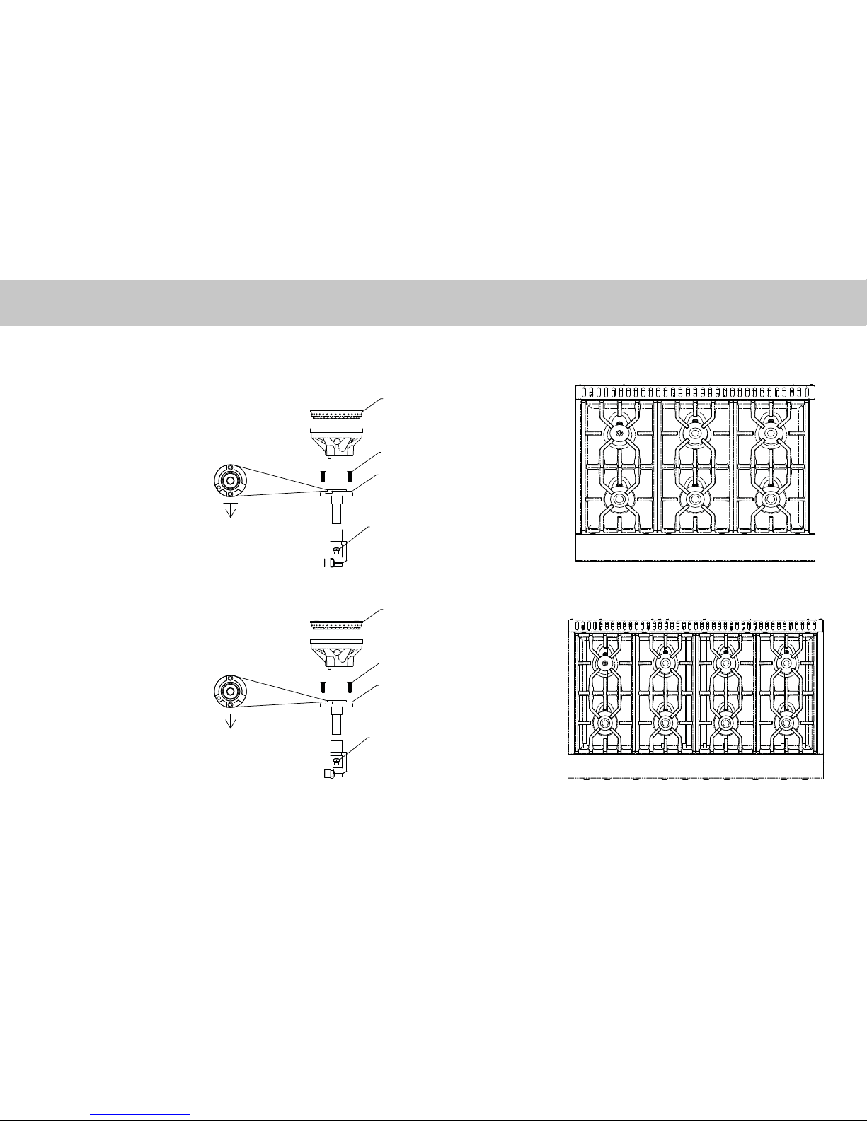
36” Surface Burner Orifice Locations
AA
B
C
Burner A #55 (1.32 mm)
Burner B #58 (1.07 mm)
Burner C #67 (.813 mm)
48” Surface Burner Orifice Locations
A
B
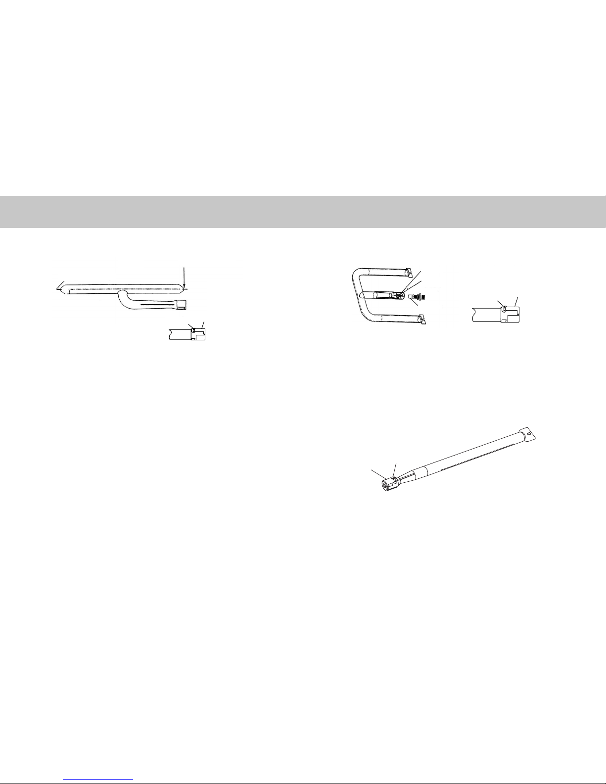
Surface Burner Conversion
Front Surface Burner Conversion
Item #1
Item #2
Item #3
Front of unit
Top View of
Venturi flange
Burner
Head
-Locate bag labeled 050299-000
-Remove screws (Item #1) with a T-20 Torx bit.
-Remove venturi flange (Item #2).
-Use a metric 10mm nut driver to remove orifice (Item
#3).
-Replace orifice with #55 from 050299-000 bag. The
orifice will have a red color code ink and 052 stamped
on the orifice.
Tech tip: Tape can be applied to the inside of the
socked to assist in the removal of the surface
burne orifices. This can prevent the orifices
from falling into the range during removal.
-After replacing the orifice, replace Item#2 venturi flange
with LP venturi flange labeled 050306-000. Note
orientation of venturi flange (refer to Top view of Venturi
flange).
-Reinstall screws and reverse procedure to reassemble.
NOTE: For proper placement of the burner head, rotate until burner head seats into groove.
Rear Surface Burner Conversion
Item #1
Item #2
Item #3
Front of unit
Top View of
Venturi flange
Burner
Head
-Locate bag labeled 050299-000
-Remove screws (Item #1) with a T-20 Torx bit.
-Remove venturi flange (Item #2).
-Use a metric 10mm nut driver to remove orifice (Item #3).
-Replace left rear orifice with #67 from 050299-000 bag.
The orifice will have a blue color code ink and 032
stamped on the orifice.
-Replace all other rear orifices with #58 from 050299-000
bag. The orifice will have a black color code ink and 042
stamped on the orifice.
Tech tip: Tape can be applied to the inside of the socked
to assist in the removal of the surface burne
orifices. This can prevent the orifices from falling
into the range during removal.
-After replacing the orifice, reinstall the current Item#2
venturi flange (it will not be replaced). Note orientation of
venturi flange (refer to Top view of Venturi flange).
-Reinstall screws and reverse procedure to reassemble.
NOTE: For proper placement of the burner head, rotate until burner head seats into groove.
(*Not applicable on
griddle models)
(*Not applicable on
griddle models)
B*
A*
(*Not applicable on
griddle models)
(*Not applicable on
griddle models)
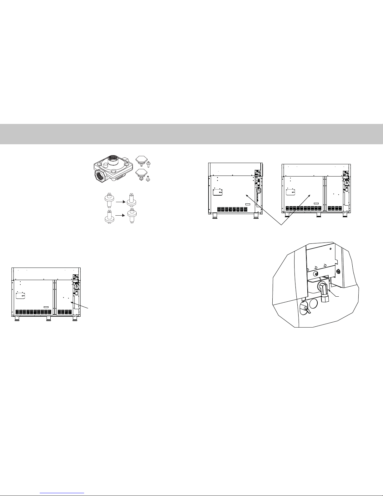
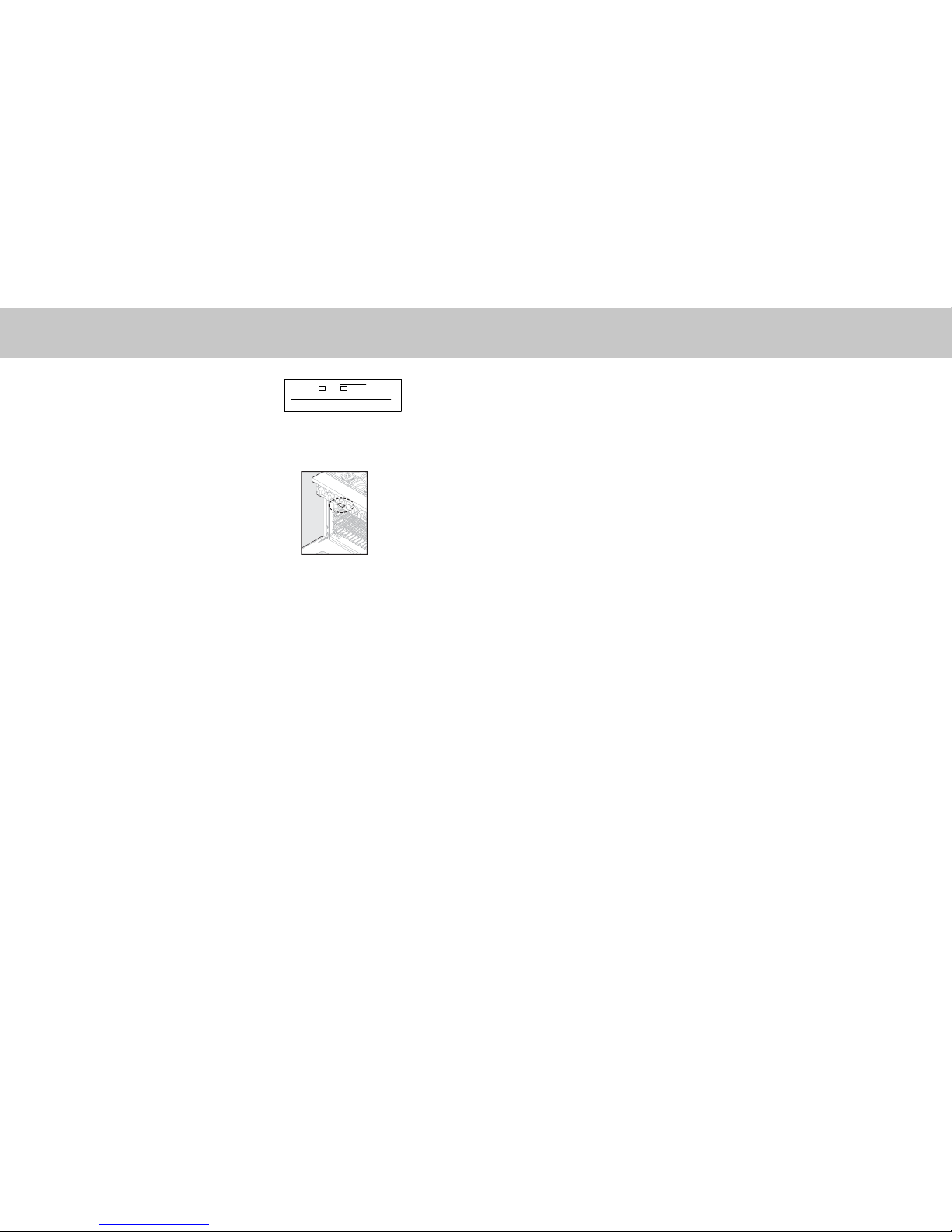
Preparing for Top Surface Conversion
Remove all grates, grate supports, surface burner caps, and griddle
NOTE: Some models may not be equipped with all parts mentioned above.
IMPORTANT: For models equipped with griddles, notice position of griddle temperature probe for
proper reinstallation. Failure to properly reinstall could result in damage to griddle temperature probe.