Viking G-6000 Instruction manual

TECHNICAL DATA
June 1, 2011
6” MODEL G-6000 DRY VALVE
RISER ASSEMBLY
The Viking Corporation, 210 N Industrial Park Drive, Hastings MI 49058
Dry 138a
1. DESCRIPTION
The Viking 6” Model G-6000 Dry Valve Riser Assembly consists of a small prole, light
weight, pilot operated valve that is used to separate the water supply from the dry
sprinkler piping, which is pressurized with air. The pilot operated valve combines an
internal diaphragm assembly that is pressurized closed with priming water, an internal
check valve to isolate the sprinkler system piping, and the Model A-1 Differential Valve
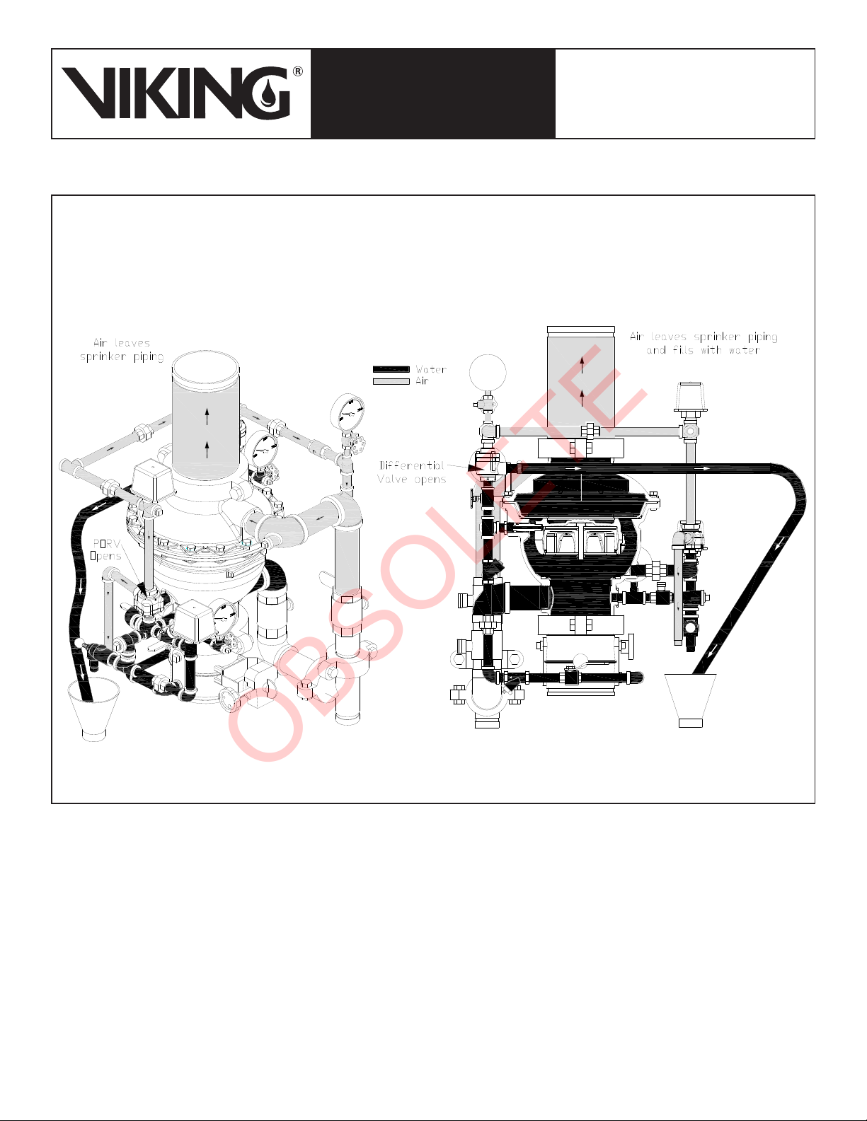
located on the valve trim that allows the valve to operate upon loss of air pressure. The
differential design of the Differential Valve allows an air supply of moderate pressure to
control a higher water supply pressure. When the air pressure in the dry pipe system
is reduced sufciently upon the differential valve due to a sprinkler head operation to
destroy the pressure differential, the differential valve will open and relieve the prim-
ing pressure from the internal diaphragm assembly. The internal diaphragm assembly
will compress, which will allow water to pass through the body of the valve and center
of the internal check valve, entering the sprinkler system piping. The Viking Model
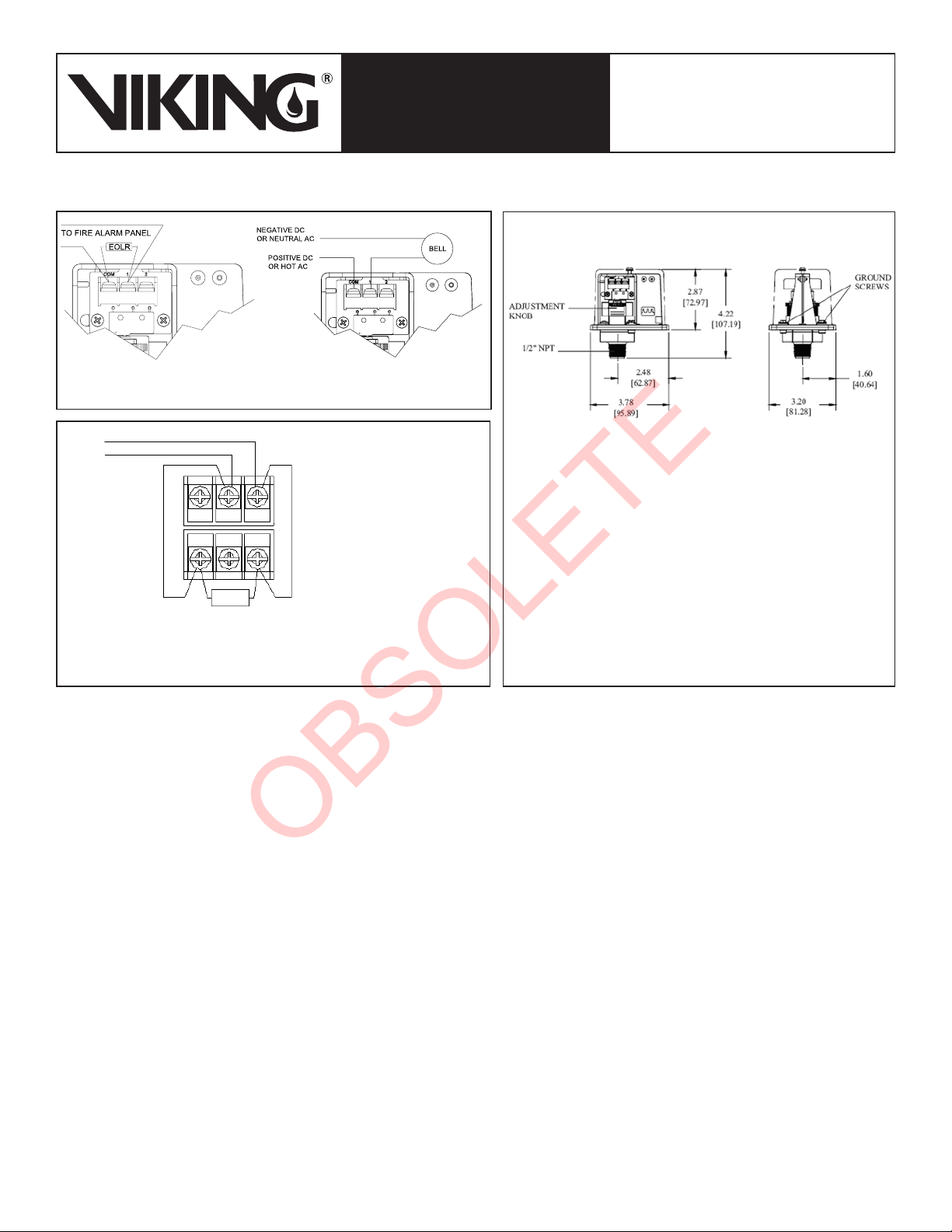
G-6000 Valve is designed to be used with a water ow pressure switch and/or water
motor gong. For systems that require an accelerator to increase the speed of water
delivery, the Viking Model E-1 Accelerator shall be used.
2. LISTING AND APPROVALS
cULus Listed - VPZV
FM Approved - Dry Pipe Valves
3. TECHNICAL DATA
Specifications:
Pressure Rating: 250 PSI (17.2 bar) Water Working Pressure
Factory Hydrostatically Tested to: 500 PSI (34.5 bar)
Air to water differential: Approximately 5.75 to 1
Friction Loss (Given in feet of Schedule 40 pipe based on Hazen & Williams formula: C = 120):feet of Schedule 40 pipe based on Hazen & Williams formula: C = 120)::
G-6000 Valve: 44.88’G-6000 Valve: 44.88’
12” Section of Pipe: 1’
Water Supply Control Valve: 14.7’
Model G-6000P Valve CvFactor: 811
Valve Color: Black
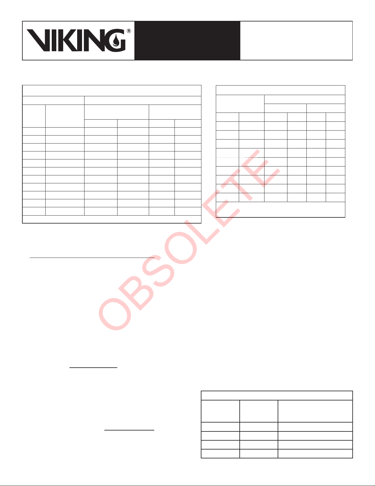
Material Specifications:
Refer to Figure 11.
Ordering Information:
Available since 2011.
Part Number: G-6000 Dry Valve Riser Assembly (See Figure 8) - 17048-1
Accessories:
Model E-1 Accelerator: 08055
Drain Manifold: 17056 (See Figure 9.)
Model LD-1 Anti-Column Device: 14800
4. INSTALLATION:
A. General Installation Instructions
1. For proper operation and approval, the valve must be installed in the vertical position as trimmed from the factory. DO NOT
install horizontally or modify the factory assembled trim except as described in this technical data page.
2. Viking recommends installing a 12” section of pipe directly above the G-6000 Dry Valve. Prior to valve maintenance, this sec-
tion of pipe may be removed to provide clearance for lifting the cover from the body.
3. The dry valve must be installed in an area not subject to freezing temperatures or physical damage. If required, provide a
valve house (enclosure) with adequate heat around the dry valve and trim. Freezing temperatures and/or excessive pressure
will damage the dry valve. When corrosive atmospheres and/or contaminated water supplies are present, it is the owner’s
responsibility to verify compatibility with the Model G-6000 Dry Valve and associated equipment.
4. The Viking Model E-1 Accelerator should be installed at the location indicated in Figure 1 when required by the installation
standard or local Authority Having Jurisdiction.
Form No. F_022111 New page 138a-m, issued June 1, 2011.
Viking Technical Data may be found on
The Viking Corporation’s Web site at
http://www.vikinggroupinc.com.
The Web site may include a more recent
edition of this Technical Data Page.
Q= Cv√∆P
S
Q = Flow
Cv = Flow Factor (GPM/1 PSI ∆P)
∆P = Pressure Loss through Valve
S = Specic Gravity of Fluid
OBSOLETE

TECHNICAL DATA
June 1, 2011
6” MODEL G-6000 DRY VALVE
RISER ASSEMBLY
The Viking Corporation, 210 N Industrial Park Drive, Hastings MI 49058
138b
5. The optional Model LD-1 Anti-Column Device may be installed to prevent water accumulation above the dry pipe valve.
6. The prime line connection shall be made upstream of the water supply control valve using 1/2” or larger pipe.
B. Air Supply Design
Calculating Trip Pressure and Air Compressor Size
To calculate the point where the water pressure will overcome the air pressure and trip the valve, divide the static system water pres-
sure by the differential (Approximately 5.75:1).
Example:
Static Water Pressure = 64 PSI (4.4 bar) → Trip Point = 64 / 5.75 = 11 PSI (0.76 bar).
The dry valve will trip when the air pressure is reduced to 11 PSI.
NFPA 13 requires the air supply to be capable of lling the entire sprinkler system to its required air pressure within 30 minutes. A com-
mon method of sizing an air compressor is to use the following formula:
Compressor Size (cfm) = .012 x V (gal)
Where V = System Volume and .012 is a common multiplier that will provide 40 PSI (2.8 bar) in 30 minutes.
The following formula may be used for air pressures different than 40 PSI:
Where:
V= Volume
P = Required Air Pressure (Trip Pressure + 15 PSI)
T = Fill time (typically 30 min.)
7.48 = gal. / ft.3
14.7 = atmospheric pressure
Compressor
Size (cfm) =
V x P
7.48 x 14.7 x T
Example:
System volume as determined by table 1 = 750 gallons
System water pressure = 73 PSI (5 bar)
Required air pressure = (73/5.75) + 15 = 28 PSI (1.93 bar)
Compressor Size (cfm) = (750 x 28) = 6.4 cfm
7.48 x 14.7 x 30
Therefore, the compressor shall be capable of providing 7 cfm.
Table 1 - Pipe Capacity for Sizing Air Compressors
Pipe Diameter Capacity
US International
Schedule 40 (1” to 6”)
Schedule 30 (8”) Schedule 10
Gal / Ft L / m Gal / Ft L / m
1” DN25 0.045 0.559 0.049 0.608
1-1/4” DN32 0.078 0.969 0.085 1.043
1-1/2” DN40 0.106 1.316 0.115 1.428
2” DN50 0.174 2.161 0.190 2.360
2-1/2” DN65 0.248 3.080 0.283 3.515
3” DN80 0.383 4.756 0.434 5.390
3-1/2” DN90 0.513 6.370 0.577 7.165
4” DN100 0.660 8.196 0.740 9.190
5” DN125 1.040 12.915 1.144 14.206
6” DN150 1.501 18.640 1.649 20.477
8” DN200 2.660 33.032 2.776 30.472
For Metric Units 1 Ft. = 0.3048 M, 1 Gal. = 3.785L
Table 2 - Air Pressure Settings
Maximum Water
Pressure
Air Pressure Setting
Minimum Maximum
PSI bar PSI bar PSI bar
50 3.4 22 1.5 27 1.8
75 5.1 26 1.8 31 2.1
100 6.8 30 2.0 35 2.4
125 8.6 34 2.3 39 2.6
150 10.3 38 2.6 43 2.9
175 12.0 42 2.8 47 3.2
200 13.7 45 3.1 50 3.4
225 15.5 49 3.4 54 3.7
250 17.2 53 3.6 58 3.9
Supervisory Pressure Switch should be set 5 PSI
(0.34 bar) below air compressor cut out.
Table 3 - Quick Reference Compressor Size
Compressor
Size (HP)
Free Air @
40 PSI (cfm)
Maximum Gallons in
System to Pump to 40 PSI
(2.8 bar) in 30 Minutes
1/6 1.0 90
1/3 2.0 180
1/2 3.1 300
1 5.9 600
OBSOLETE

TECHNICAL DATA
June 1, 2011
6” MODEL G-6000 DRY VALVE
RISER ASSEMBLY
The Viking Corporation, 210 N Industrial Park Drive, Hastings MI 49058
Dry 138c
Figure 1 - Trim Components
Figure 2 - Air Supply Options
OBSOLETE

TECHNICAL DATA
June 1, 2011
6” MODEL G-6000 DRY VALVE
RISER ASSEMBLY
The Viking Corporation, 210 N Industrial Park Drive, Hastings MI 49058
138d
C. Air Supply Installation
1. Install the required air supply as described in Viking technical data page 105a-e. The size of the compressor and amount of
air required should be determined in accordance with Table 1. The air or nitrogen supply to the dry pipe system must be clean,
dry, and oil free.
2. Automatic air supplies must be regulated, restricted, and from a continuous source. A Viking Air Maintenance Device should
be installed on each system equipped with a tank mounted compressor, plant air or nitrogen. For riser mounted compressors
with a capacity less than 5.5 ft3/min at 10 PSI (0.154 mPSI (0.154 m3/min at 0.7 bar), NFPA 13 does not require an air maintenance device.NFPA 13 does not require an air maintenance device.
In addition, the use of an air maintenance device with riser mounted compressors can lead to compressor “short cycling”.
Viking always recommends using a tank mounted compressor with air maintenance device. This can become critical when
accelerators are installed on the system.
D. Pressure Switch Wiring;
Wire the Alarm Pressure Switch (PS10) and Air Supervisory Switch (PS40), and adjust pressure settings as shown in Figures 3 - 5.
E. Air Leakage Test:
Perform air leakage test at 40 PSI (2.8 bar) for 24 hours per NFPA 13. If pressure loss of 1.5 PSI (0.1034 bar) or greater occurs, repair
leaks.
F. Hydrostatic Test:
The Dry System, including sprinkler piping and sprinklers shall be hydrostatically tested at 200 PSI (13.8 bar) and maintained for 2
hours, in accordance with NFPA 13. Systems normally subjected to working system pressures in excess of 150 PSI (10.3 bar) shall be
tested at a pressure of 50 PSI (3.45 bar) in excess of system working pressure.
G. Placing the Valve in Service:
When the dry pipe system is ready to be placed in service, verify that all equipment is adequately heated and protected to prevent
freezing and physical damage.
1. Verify that the water supply main control valve supplying the dry valve is closed.
2. Close the prime valve.
3. Open the main drain valve.
4. Drain all water from the dry pipe system. If the system has operated, or if water has entered the system, allow enough time
to completely drain the system.
5. Close the main drain valve.
6. Open the flow test valve.
TO FIRE
ALARM
PANEL
COM
12
2
1
COM
HIGH
AIR
LOW
AIR
PS40-2
WITH NORMAL SYSTEM
PRESSURE APPLIED HIGH
- TERMINAL 1 WILL CLOSE
ON PRESSURE INCREASE.
EOLR
DWG# 930-2
Figure 3 - Alarm Pressure Switch Wiring
(Alarm Pressure Switch should be set to 5 PSI (0.34 bar)
Figure 4 - Air Supervisory Switch Wiring
(High Air should be set to 10 PSI (0.7 bar) above compressor cut out)
(Low Air should be set to 5 PSI (0.34 bar) below comperssor cut out) Figure 5 - Pressure Adjustment
FIELD ADJUSTMENTS:
Alarm Pressure Switch: The operating point of the switch can be
adjusted to any point between 4 PSI (0.27 bar) and 8 PSI (0.55 bar)
by turning the adjustment knob(s) clockwise to raise the actuation
point or counter-clockwise to lower the actuation point.
Air Supervisory Switch: The operating point of the switches can
be adjusted to any point between 10 PSI (0.7 bar) and 60 PSI
(4.1 bar) by turning the adjustment knob(s) clockwise to raise the
actuation point or counter-clockwise to lower the actuation point.
The high and low switches are adjusted independently.
OBSOLETE

TECHNICAL DATA
June 1, 2011
6” MODEL G-6000 DRY VALVE
RISER ASSEMBLY
The Viking Corporation, 210 N Industrial Park Drive, Hastings MI 49058
Dry 138e
Figure 6 - Set Position
5. OPERATION
A. In the Set Position:
When air pressure is introduced into the sprinkler piping, the sensing end of the differential valve is pressurized. This closes the
differential valve, preventing prime water from escaping the prime chamber of the dry pipe valve. When prime water enters the
prime chamber, the rolling diaphragm is pressurized, causing it to expand downward onto the water seat.
7. Establish air pressure on the system.
8. When air pressure has been established, open the priming valve. Prime water pressure will enter and expand the valve’s
internal diaphragm assembly onto the valve seat, effectively closing the valve. Verify prime pressure has been established on
the prime pressure gauge.
9. Verify that no water flows from the drip check when the plunger is pushed.
10. When the priming pressure has been verified as being established, slowly open the water supply control valve (not shown).
11. When flow is developed from the flow test valve, CLOSE the flow test valve.
12. Fully open the water supply main control valve.
13. Secure all valves in their normal operating position.
14. Notify Authorities Having Jurisdiction and those in the affected area that the system is in service.
15. The system is now fully operational.
H. Operational Test:
An operational test shall be performed on the system in accordance with NFPA 13 as follows:
1. Open the instector’s test connection.
2. Record the time to trip the valve.
3. Record the time for water delivery to the inspector’s test connection.
OBSOLETE

TECHNICAL DATA
June 1, 2011
6” MODEL G-6000 DRY VALVE
RISER ASSEMBLY
The Viking Corporation, 210 N Industrial Park Drive, Hastings MI 49058
138f
Figure 7 - Loss of System Air Pressure
B. Loss of System Air Pressure:
When a sprinkler operates or air pressure is lost, the sensing end of the differential valve loses pressure and the differential valve
opens. Prime water is drained from the prime chamber, causing the dry pipe valve to open, lling the sprinkler piping with water. Water
from the intermediate chamber of the dry pipe valve pressurizes the sensing end of the PORV, causing the PORV to open. The open
PORV vents air pressure from the air supply, preventing the differential valve from closing and re-establishing prime pressure.
6. INSPECTIONS, TESTS, & MAINTENANCE
It is imperative that the system is inspected and tested on a regular basis. The frequency of the inspections may vary due to contami-
nated water supplies, corrosive water supplies, corrosive atmospheres, as well as the condition of the air supply to the system. For
minimum testing and inspection requirements, refer to NFPA 25. In addition, the Authority Having Jurisdiction may have additional
testing, and inspection requirements that must be followed. Viking does not require internal inspection of the valve as part of routine
inspection and testing. Internal maintenance is generally only required for valve repairs and internal component replacement.
Maintenance of the G-6000 Dry Valve shall be conducted in accordance with the instructions in section 6.III.
WARNING: DO NOT SEPARATE THE COVER AND BODY SECTIONS UNLESS THE VALVE IS LEAKING.
I. INSPECTION
Weekly inspection is recommended. If the system is equipped with a low air (or nitrogen) alarm, monthly inspections may be adequate.
1. Check pressure gauges located on the supply side and system side of the dry valve. Verify that the proper ratio of air (or
nitrogen) pressure to water supply pressure is being maintained. Refer to Table 1.
OBSOLETE

TECHNICAL DATA
June 1, 2011
6” MODEL G-6000 DRY VALVE
RISER ASSEMBLY
The Viking Corporation, 210 N Industrial Park Drive, Hastings MI 49058
Dry 138g
2. Verify that the intermediate chamber of the dry valve is free of water. No water should flow from the drip check when the
plunger is pushed.
3. Verify that there is no air coming out of the 1/2” outlet of the PORV.
4. If equipped with a Viking accelerator:
Check the air pressure gauge located on the top of the accelerator. Air pressure in the upper chamber of the accelerator
should equal the pneumatic pressure maintained in the system.
5. Verify that the water supply main control valve is open and all trim valves are in their normal operating position.
6. Check for signs of mechanical damage and/or corrosive activity. If detected, perform maintenance as required or, if necessary,
replace the device.
7. Verify that dry valve and trim are adequately heated and protected from freezing and physical damage.
II. TESTS
Quarterly Tests
A. Water Flow Alarm Test
Quarterly testing of water ow alarms is recommended and may be required by the Authority Having Jurisdiction.
1. Notify the Authority Having Jurisdiction and those in the area affected by the test.
2. To test the local electric alarm (if provided) and/or mechanical water motor gong (if provided), OPEN the alarm test valve in
the dry valve trim.
Electric alarm pressure switches should activate.
Electric local alarms should be audible.
The local water motor gong should be audible.
Verify that remote station alarm signals (if provided) were received.
3. When testing is complete, close the alarm test valve.
4. Verify:
All local alarms stop sounding and alarm panels (if provided) reset.
All remote station alarms reset.
All supply piping to water motor properly drains.
5. Verify that the alarm test valve is CLOSED.
6. Verify that the intermediate chamber of the dry valve is free of water. No water should flow from the drip check when the
plunger is pushed.
7. Notify the Authority Having Jurisdiction and those in the affected area that testing is complete.
B. Main Drain Test
Quarterly performance of the Main Drain Test is recommended and may be required by Authorities Having Jurisdiction to verify integrity
of the water supply.
1. Notify the Authority Having Jurisdiction and those in the area affected by the test.
2. Record pressure reading from the water supply pressure gauge.
3. Verify that the intermediate chamber of the dry valve is free of water. No water should flow from the drip check when the
plunger is pushed.
4. Verify that there is no air coming out of the 1/2” outlet of the PORV.
5. Verify that the dry pipe system is pressurized at or above the minimum pressure recommended in Table 2 for the water supply
pressure available.
6. Fully OPEN the main drain valve located on the base of the dry valve.
7. When a full flow is developed from the main drain, record the residual pressure from the water supply pressure gauge.main drain, record the residual pressure from the water supply pressure gauge., record the residual pressure from the water supply pressure gauge.
8. When the test is complete, SLOWLY CLOSE the main drain.main drain..
9. Compare test results with previous flow information. If deterioration of the water supply is detected, take appropriate steps to
restore adequate water supply.
10. Verify that normal water supply pressure and system pneumatic pressure have been restored, and that all alarm devices and
valves are secured in normal operating position.
11. Notify the Authority Having Jurisdiction that the test is complete. Record and/or provide notification of test results as required
by the Authority Having Jurisdiction.
C. Low Air Alarm Test
Quarterly testing of low air alarms is recommended.
1. Notify the Authority Having Jurisdiction and those in the area affected by the test.
2. Close the water supply main control valve supplying the dry valve.
3. Close the priming valve.
4. Open the flow test valve (located on the inlet of the dry valve).
5. If the dry valve being tested is equipped with a Viking Model E-1 Accelerator, performing step 6 of this test will cause the
a.
a.
b.
c.
d.
a.
b.
c.
OBSOLETE

TECHNICAL DATA
June 1, 2011
6” MODEL G-6000 DRY VALVE
RISER ASSEMBLY
The Viking Corporation, 210 N Industrial Park Drive, Hastings MI 49058
138h
accelerator to operate. A burst of air from the vent in the bottom of the accelerator will indicate operation of the accelerator.
However, with the water supply main control valve CLOSED and the flow test valve OPEN, operation of the accelerator should
not trip the dry valve.
6. Low Air Alarm Test:
Verify that the water supply main control valve is closed and the flow test valve is open.
Gradually open the main drain valve on top of the dry valve to simulate operation of the dry system. Observe and record
the pressure at which the low air alarm operates.
7. Close the main drain valve.
8. Perform steps 1 through 15 of section 4.G - Placing the Valve in Service.
Trip Tests
Partial Flow Trip Tests are conducted with the water supply main control valve partially closed to minimize the amount of water enter-
ing the system during the test. Performance of a Partial Flow Trip Test is recommended during warm weather at least annually except
when a Full Flow Trip Test is conducted. Partial Flow Trip Tests may verify operation of equipment and devices but do not simulate
operation of the system in re conditions.
Full Flow Trip Tests are conducted with the water supply main control valve fully open. The dry valve is operated by opening the system
test valve to simulate the opening of a sprinkler in re conditions. When the dry valve operates, the sprinkler piping will be ooded
with water.
Performance of a Full Flow Trip Test is recommended during warm weather at least once every three years. More frequent testing may
be required by the Authority Having Jurisdiction.
A. Full Flow Trip Test
1. Notify the Authority Having Jurisdiction and those in the area affected by the test.
2. Fully open the flow test valve (located on the base of the dry valve) to flush away any accumulation of foreign material.
3. Close the flow test valve.
4. Record water supply pressure and system air pressure.
5. Open the remote system test valve to simulate operation of the dry system. Record:
Elapsed time from opening of the test valve to operation of the dry valve. System pressure when the dry valve oper-
ated.
Elapsed time from opening of the test valve to development of full flow of water from the system test connection.
Any other information required by the Authority Having Jurisdiction.
6. Verify that alarms operate properly.
7. Allow water to flow from the system test connection until it appears clear and clean.
8. When test is complete, close the water supply main control valve.
9. Perform steps 1 through 15 of section 4.G - Placing the Valve in Service.
10. Verify that the water supply main control valve is open, and all other valves are in their normal operating position.
B. Partial Flow Trip Test
1. Notify the Authority Having Jurisdiction and those in the area affected by the test.
2. Record water supply pressure and system air pressure.
3. Fully open the flow test valve (located on the base of the dry valve) to flush away any accumulation of foreign material.
4. CLOSE the water supply main control valve as far as possible while maintaining full flow from the flow test valve. CLOSE the
flow test valve.
5. Open the main drain valve to simulate operation of the system.
6. Note (for records) water supply pressure and system air pressure when the dry valve operates.
7. CLOSE the water supply main control valve and OPEN the main drain IMMEDIATELY, when test is complete.
8. Perform steps 1 through 15 of section 4.B - Placing the Valve in Service.
9. Verify that the water supply main control valve is open, all other valves are in their normal operating position.
III. MAINTENANCE
1. Close the water supply main control valve, placing the system out of service.
2. Open the flow test valve located in the base of the dry valve.
3. Close the air (or nitrogen) supply to the dry system piping.
4. Close the priming valve.
5. Relieve all pressure from the dry system piping. If the system has operated, open the main drain valve to allow the system
to drain completely.
6. Confirm that all three pressure gauges read zero.
a.
b.
a.
b.
c.
OBSOLETE

TECHNICAL DATA
June 1, 2011
6” MODEL G-6000 DRY VALVE
RISER ASSEMBLY
The Viking Corporation, 210 N Industrial Park Drive, Hastings MI 49058
Dry 138i
A. Removing the Cover from the Body
1. Remove the 6” grooved coupling from the top of the dry valve.
2. Remove the section of pipe directly above the dry valve, if provided.
3. Open both of the 1/2” unions on the air supply line.
4. Remove the 2” coupling below the main drain, if provided.
5. Remove the 16 cover screws.
6. The cover and trim that is still connected may now be removed from the valve body. (It may be necessary to pry the valve
open as the diaphragm may bond itself to the cover and body over time.)
B. Removing / Replacing the Check Diaphragm
1. The check diaphragm may be lifted from the valve body.
2. If necessary, replace the check diaphragm.
C. Inspecting the Prime Chamber and Coupling for leaks
If desired, it is possible to set the G-6000 Dry Pipe Valve and inspect for leaks with the cover removed.
1. Remove the A-1 Differential Valve from the prime line and temporarily install a pipe plug.
2. Slowly open the prime valve. Confirm that the valve is primed by reading the prime pressure gauge.
3. With prime water established, partially open the main water supply control valve.
4. Visually inspect the inside of the dry pipe valve for leaks.
5. Close the main water supply control valve.
D. Removing / Replacing the Prime Coupling
1. Using a wrench on the flats of the coupling, remove the coupling from the valve body.
2. Inspect the coupling and 2 O-rings. Replace if necessary.
E. Removing / Replacing the Prime Chamber Assembly
1. The prime chamber assembly is now held in place by two flanges on the outside diameter of the assembly. Slide the prime
chamber assembly toward the prime line and remove from the body.
2. Inspect and replace if necessary.
3. Inspect the seat. The seat should be clean and free of foreign material. If the Seat is damaged, the G-6000 Dry Pipe Valve
must be replaced.
F. Re-Assembling the Valve
1. Verify that the prime piston is fully extended downward.
2. Place the prime chamber assembly in the valve body. Make sure the two flanges are positioned in the groove.
3. Thread the prime coupling into the valve body. Make sure the end of the prime coupling is inserted into the prime chamber
assembly.
4. Lay the check diaphragm into the valve body.
5. Position the cover onto the valve body, and install and tighten the cover screws.
6. Re-install any trim that was removed.
7. Place the valve in service by following the steps in Section 4.G.
7. AVAILABILITY
The Viking Model G-6000 Dry Valve Riser Assembly is available through a network of domestic and international distributors. See the
Viking Corp. Web site for closest distributor or contact The Viking Corporation.
OBSOLETE

TECHNICAL DATA
June 1, 2011
6” MODEL G-6000 DRY VALVE
RISER ASSEMBLY
The Viking Corporation, 210 N Industrial Park Drive, Hastings MI 49058
138j
Part Number 17048-1 includes:
1Model G-6000 Valve
1 Model G-6000 Dry Trim
1 12” Section of Schedule 10 Pipe with
Coupling
1 Air Pressure Supervisory Switch (PS40-2A)
1 Alarm Pressure Switch (PS10-2A)
1Water Supply Control Valve
Figure 8 - Complete Assembly
Figure 9 - Optional Accessories
Accessories:
08055 Model E-1 Accelerator
14800 Model LD-1 Anti-Column Device
17056 Drain Manifold
OBSOLETE

TECHNICAL DATA
June 1, 2011
6” MODEL G-6000 DRY VALVE
RISER ASSEMBLY
The Viking Corporation, 210 N Industrial Park Drive, Hastings MI 49058
Dry 138k
Figure 10 - Installation Dimensions
OBSOLETE

TECHNICAL DATA
June 1, 2011
6” MODEL G-6000 DRY VALVE
RISER ASSEMBLY
The Viking Corporation, 210 N Industrial Park Drive, Hastings MI 49058
138l
Figure 11 - G-6000 Valve Components List/Replacement Parts
Item
Number
Part
Number Description Material Number
Required
1 -- Body 64-45-12 Ductile Iron 1
2 -- Seat UNS-S30400 Stainless Steel 1
3 -- Anaerobic Adhesive -- 1
4 17081 Prime Chamber Assembly Brass, EPDM, Nitrile, 304 Stainless Steel, Bronze Alloy 1
5 * O-Ring EPDM 1
6 * O-Ring EPDM 1
716299 Coupling UNS-S17400 Stainless Steel 1
816552 Check Diaphragm EPDM 1
9 -- Cover 65-45-12 Ductile Iron 1
10 08083 1/2-13 x 1-1/2” HHS UNS-S30400 Stainless Steel 16
11 -- Data Plate Aluminum 2
12 -- Tack Alloy Carbon Steel 4
-- Replacement part not available.
* Indicates part available only in a Sub-Assembly, as indicated below.
Sub-Assembly
5, 6 17445 O-Ring Replacement Kit
OBSOLETE

TECHNICAL DATA
June 1, 2011
6” MODEL G-6000 DRY VALVE
RISER ASSEMBLY
The Viking Corporation, 210 N Industrial Park Drive, Hastings MI 49058
Dry 138m
Item
Number Part Number Description Material Number
Required
1 15459 Seat Brass UNS-C36000 1
2 -- Body Brass UNS-C84400 1
3 14948 Diaphragm Polyester Fabric and EPDM Elastomer 1
4 04735A Upper Diaphragm Bellofram 1
5 12470 Screw, #10-24 x 1-1/4” Long Steel, Zinc Coated 3
6 -- Cover Brass UNS-C84400 1
7 -- Spacer Brass UNS-C84400 1
804736A Piston Polycarbonate 1
-- Replacement part not available.
Sub-Assemblies
1-8 15461 Replacement A-1 Differential Valve
3-5, 8 15763 Maintenance Kit
Figure 12 - Model A-1 Differential Valve
OBSOLETE

THIS PAGE INTENTIONALLY
LEFT BLANK
Form No. F_022111 New page 138a-m, issued June 1, 2011.
OBSOLETE
Table of contents
Other Viking Control Unit manuals

Viking
Viking A-1 Instruction manual

Viking
Viking SA--25 Instructions for use

Viking
Viking G-2000P Instruction manual

Viking
Viking VXD Instruction manual

Viking
Viking G-2000 Instruction manual

Viking
Viking F-1 Instruction manual

Viking
Viking TMS-RDMA User manual

Viking
Viking G-3000P Instruction manual

Viking
Viking VXD Instruction manual

Viking
Viking G-4000P Instruction manual
Popular Control Unit manuals by other brands

Supermicro
Supermicro MicroBlade MBI-6218G-T81X user manual

Parker
Parker S5A Installation, Service and Parts Information

Nice
Nice mindy A60 Instructions and warnings

Harman
Harman AMX HPX-AV102-MDP-R quick start guide

SimTech
SimTech SimCom SIM340 Hardware design

AQUATROL
AQUATROL POWERFLO Series Service manual