TECHNICAL DATA
May 7, 2014 Deluge Valves 218e
The Viking Corporation, 210 N Industrial Park Drive, Hastings MI 49058
Telephone: 269-945-9501 Technical Services: 877-384-5464 Fax: 269-818-1680 Email: techsvcs@vikingcorp.com
DELUGE VALVE, MODEL F-1
STRAIGHT THROUGH STYLE
2-1/2” (DN65) - 8” (DN200)
C. Valve Removed From Service
NOTE: WHEN A VALVE HAS BEEN REMOVED FROM SERVICE AND IS SUBJECT TO FREEZING OR WILL BE OUT OF SERVICE FOR
AN EXTENDED PERIOD OF TIME, ALL WATER MUST BE REMOVED FROM THE PRIMING CHAMBER, TRIM PIPING, WATER SUPPLY
PIPING AND OTHER TRAPPED AREAS.
5. OPERATION (Refer to Figure 2.)
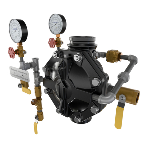
The Viking Model F-1 Deluge Valve has an inlet chamber, an outlet chamber and a priming chamber. The inlet chamber and outlet
chamber are separated from the priming chamber by the clapper (5) and diaphragm (6).
In the set condition:
System pressure is supplied to the priming chamber through a restricted priming line (trim) equipped with a check valve. System water
supply pressure trapped in the priming chamber holds the clapper (5) on seat (2) due to area differential design. Clapper (5) separates
the inlet chamber from the outlet chamber, keeping the outlet chamber and system piping dry.
In fire conditions:
When the release system operates, pressure is released from the priming chamber faster than it is supplied through the restricted
priming line. Water supply pressure in the inlet chamber forces the clapper (5) off from seat (2), allowing water to flow through the outlet
and into the system and alarm devices.
For Deluge Valves equipped with Conventional Trim:
When the deluge valve operates, the air side of the PORV looses pressure, causing the PORV to operate. When the PORV operates, it
continually vents the priming chamber to prevent the deluge valve from resetting even if the open releasing devices close. The deluge
valve can only be reset after the system is taken out of service, and the outlet chamber of the deluge valve and associated trim piping
is depressurized and drained.
6. INSPECTIONS, TESTS AND MAINTENANCE
I. Inspection
It is imperative that the system is inspected and tested on a regular basis. The frequency of the inspections may vary due to con-
taminated water supplies, corrosive water supplies or corrosive atmospheres. Also, the alarm devices, detection systems or other
connected trim may require a more frequent schedule. For minimum maintenance and inspection requirements, refer to NFPA 25. In
addition, the Authority Having Jurisdiction may have additional maintenance, testing, and inspection requirements that must be fol-
lowed. The following recommendations are minimum requirements. (For additional information, refer to Viking Trim Charts and System
Data describing systems with the release system used.)
A. Weekly:
Weekly visual inspection of the Viking Deluge Valve is recommended.
Verify that the Main Water Supply Control Valve (D.1) is open and that all other valves are in their normal** operating position
and appropriately secured.
Check for signs of mechanical damage, leakage, and/or corrosive activity. If detected, perform maintenance as required. If neces-
sary, replace the device.
Verify that the valve and trim are adequately heated and protected from freezing and physical damage.
II. Tests
A. Quarterly Water Flow Alarm Test
Notify the Authority Having Jurisdiction and those in the area affected by the test.
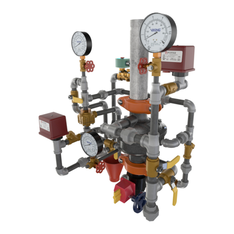
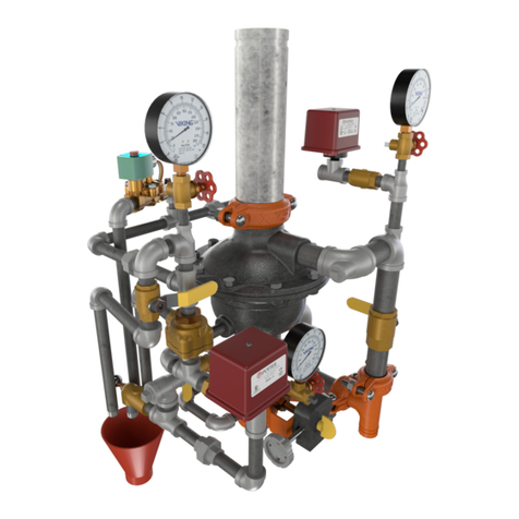
To test the local electric alarm (if provided) and/or mechanical water motor alarm (if provided), OPEN the alarm test valve (B.10)
in the deluge valve trim.
Electric alarm pressure switches (if provided) should activate.
Electric local alarms should be audible.
The local water motor gong should be audible.
If equipped with remote station alarm signaling devices, verify that alarm signals were received.
When testing is complete, CLOSE the alarm test valve (B.10).
Verify:
All local alarms stop sounding and alarm panels (if provided) reset.
All remote station alarms reset.
Supply piping to water motor alarm properly drains.
Verify that the alarm shut-off valve (B.6) is OPEN, and the alarm test valve (B.10) is CLOSED.
Verify that the outlet chamber is free of water. No water should flow from the drip check (B.14) when the plunger is pushed.
Notify the Authority Having Jurisdiction and those in the affected area that testing is complete.
1.
2.
3.
1.
2.
a.
b.
c.
d.
3.
4.
a.
b.
c.
5.
6.
7.
