manuals.online logo
Brands
  1. Home
  2. •
  3. Brands
  4. •
  5. Viking
  6. •
  7. Cooktop
  8. •
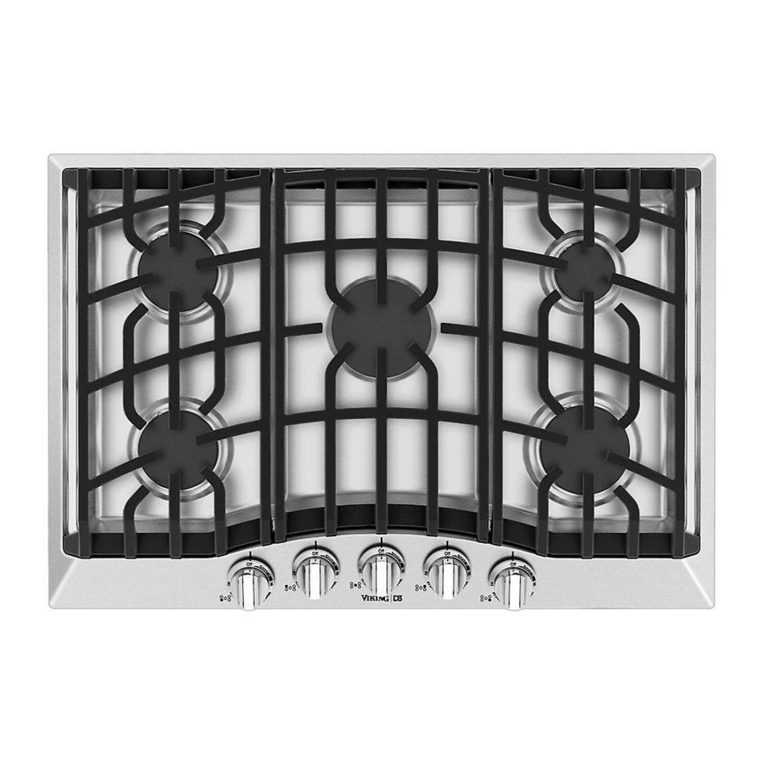
  9. Viking Designer DGVU260-5B User manual

Viking Designer DGVU260-5B User manual

This manual suits for next models

2

Other Viking Cooktop manuals

Viking D3 Series User manual

Viking

Viking D3 Series User manual

Viking Designer DECU105 User manual

Viking

Viking Designer DECU105 User manual
Viking DECU1054BSB User manual

Viking

Viking DECU1054BSB User manual

Viking Designer DERT362-5B User manual

Viking

Viking Designer DERT362-5B User manual

Viking Designer DETU200-4B User manual

Viking

Viking Designer DETU200-4B User manual

Viking Designer DETU200-4B User manual

Viking

Viking Designer DETU200-4B User manual

Viking Designer DGVU User manual

Viking

Viking Designer DGVU User manual

Viking F20528 User manual

Viking

Viking F20528 User manual

Viking Designer DGSU100-4B User manual

Viking

Viking Designer DGSU100-4B User manual

Viking VGSU530 User manual

Viking

Viking VGSU530 User manual

Viking Designer DETU200-4B User manual

Viking

Viking Designer DETU200-4B User manual

Viking CVECU530 User manual

Viking

Viking CVECU530 User manual

Viking DECU105-4B 30"W User manual

Viking

Viking DECU105-4B 30"W User manual

Viking RDGSU2005B User manual

Viking

Viking RDGSU2005B User manual

Viking RVEC3305BSB User manual

Viking

Viking RVEC3305BSB User manual

Viking Professional VICU266-6B User manual

Viking

Viking Professional VICU266-6B User manual

Viking DGCU105-4B User manual

Viking

Viking DGCU105-4B User manual

Viking Electric Rangetops/Ranges User manual

Viking

Viking Electric Rangetops/Ranges User manual

Viking VECU1064BSB User manual

Viking

Viking VECU1064BSB User manual

Viking F20679C User manual

Viking

Viking F20679C User manual

Viking CNVGSU User manual

Viking

Viking CNVGSU User manual
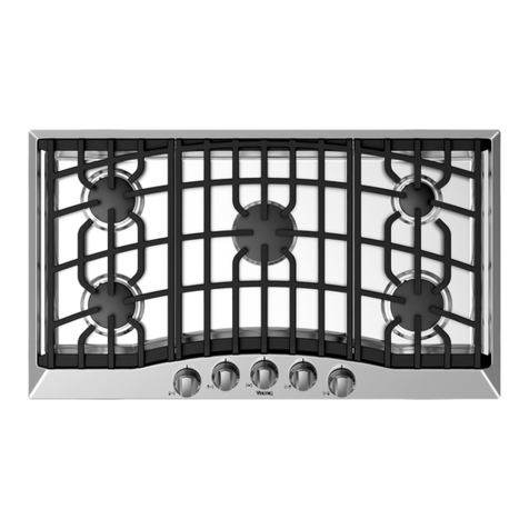
Viking F20111B User manual

Viking

Viking F20111B User manual

Viking M0908F60094G User manual

Viking

Viking M0908F60094G User manual

Viking MVEC630 User manual

Viking

Viking MVEC630 User manual

Popular Cooktop manuals by other brands

Fisher & Paykel CE302CBX2 manual

Fisher & Paykel

Fisher & Paykel CE302CBX2 manual

Whirlpool GJC3634RB00 parts list

Whirlpool

Whirlpool GJC3634RB00 parts list

Whirlpool ACH7324/BLV Use, care and installation guide

Whirlpool

Whirlpool ACH7324/BLV Use, care and installation guide

Frigidaire Professional FPDF4085KF Important safety instructions

Frigidaire

Frigidaire Professional FPDF4085KF Important safety instructions

Bonnet OPTIMUM 700 Technical instructions

Bonnet

Bonnet OPTIMUM 700 Technical instructions

Jenn-Air JGCP430 installation instructions

Jenn-Air

Jenn-Air JGCP430 installation instructions

Bompani BO374AA/E User instructions

Bompani

Bompani BO374AA/E User instructions

Kleenmaid cooking GCTK9011 Instructions for use and warranty details

Kleenmaid

Kleenmaid cooking GCTK9011 Instructions for use and warranty details

Waldorf RN8603E-B Technical data sheet

Waldorf

Waldorf RN8603E-B Technical data sheet

Whirlpool SMP658CNEIXL quick guide

Whirlpool

Whirlpool SMP658CNEIXL quick guide

Electrolux E36IC80ISS - 36" Induction Cooktop Wiring diagram

Electrolux

Electrolux E36IC80ISS - 36" Induction Cooktop Wiring diagram

Wolf CI243C/B Use and care guide

Wolf

Wolf CI243C/B Use and care guide

Fulgor Milano F5PGK305S1 installation instructions

Fulgor Milano

Fulgor Milano F5PGK305S1 installation instructions

Wells WV-2HFG owner's manual

Wells

Wells WV-2HFG owner's manual

Samsung NA36N9755 installation manual

Samsung

Samsung NA36N9755 installation manual

Miele KM 404 operating instructions

Miele

Miele KM 404 operating instructions

Lacor 69562 Instructions for use and maintenance

Lacor

Lacor 69562 Instructions for use and maintenance

Keating Of Chicago MG-2 manual

Keating Of Chicago

Keating Of Chicago MG-2 manual

manuals.online logo
manuals.online logoBrands
  • About & Mission
  • Contact us
  • Privacy Policy
  • Terms and Conditions

Copyright 2025 Manuals.Online. All Rights Reserved.

Viking Installation Gui e
Designer DGVU Built-In Gas Cooktops
Table of Contents
Warnings & Important Safety Instructions _______________________________________________3
Dimensions (30”) ____________________________________________________________________6
Dimensions (36”) ____________________________________________________________________7
Specifications _______________________________________________________________________8
Cutout Dimensions __________________________________________________________________9
Down raft Dimensions ______________________________________________________________9
Clearance Dimensions (Proximity to Cabinets)__________________________________________10
Clearance Dimensions (Woo /Composite or Steel Overlay) ______________________________11
Electrical & Gas Requirements _______________________________________________________12
General Information ________________________________________________________________14
Installation_________________________________________________________________________15
LP Conversion __________________________________________________________________16
LP Pressure Regulator Conversion_________________________________________________17
Gas & Electrical Connection ______________________________________________________18
Bracket Installation ______________________________________________________________18
Final Installation ________________________________________________________________18
Final Preparation ___________________________________________________________________19
Performance Checklist ______________________________________________________________19
Service & Registration_______________________________________________________________20
IMPORTANT
• Before beginning, rea these instructions
thoroughly an carefully.
• Installation an service must be
performe by a qualifie installer, service
agency, or the gas supplier.
•DO NOT remove permanently affixe
labels, warnings, or plates from the
pro uct as this may voi the warranty.
• Observe all local an national co es,
requirements an or inances.
• Installation must conform with local co es
or in the absence of co es, the National
Fuel Gas Co e, ANSI Z223.1- latest
e ition an the National Electrical Co e,
ANSI/NFPA 70- latest e ition.
In Canada: Installation must be in
accor ance with the current CAN/CGA
B149.1 & 2 Gas Installation co es an with
the current CSA C22.1 Cana ian Electrical
Co es Part 1 an /or local co es.
• Installation of any gas-fire equipment
shoul be ma e by a license plumber.
• A manual gas shut-off valve must be
installe in the gas supply line ahea of
the cooktop in the gas stream for safety
an ease of service.
In Massachusetts: This appliance must be
installe by a license plumber or gas-fitter.
A “T” han le manual gas valve must be
installe in the gas supply line to the
appliance.
• Installers shoul leave these instructions
with the consumer who shoul retain them
for the local inspector’s use an for future
reference.
3
–Please Read and Follow
Your s fety nd the s fety of others is
very import nt.
We have provided many important safety
messages in this manual and on your
appliance. ALWAYS read and obey all
safety messages.
his is the safety alert symbol. his
symbol alerts you to hazards that
can kill or hurt you and others.
All safety messages will be preceded by
the safety alert symbol and the word
“DANGER,” “WARNING” or “CAU ION.”
hese words mean:
H z rds or uns fe pr ctices
which WILL result in severe person l
injury or de th
DANGER
H z rds or uns fe pr ctices
which COULD result in severe person l
injury or de th
H z rds or uns fe pr ctices which
COULD result in minor person l injury
or property d m ge.
All safety messages will identify the
hazard, tell you how to reduce the chance
of injury, and tell you what can happen if
the instructions are not followed.
WARNING
CAUTION
IMPORTANT
4
–Please Read and Follow
FIRE/EXPLOSION
HAZARD
IF HE INFORMA ION IN
HIS MANUAL IS NO
FOLLOWED EXAC LY, A FIRE OR
EXPLOSION MAY RESUL CAUSING
PROPER Y DAMAGE, PERSONAL
INJURY, OR DEA H.
•DO NOT store or use gasoline or other
flammable vapors and liquids in the
vicinity of this or any other appliance.
• WHAT TO DO IF YOU SMELL GAS:
–DO NOT try to light any appliance.
–DO NOT touch any electrical switch.
–DO NOT use any phone in your
building.
–Immediately call your gas supplier
from a neighbor’s phone.
–Follow the gas supplier’s instructions.
–If you cannot reach your gas supplier,
call the fire department.
• Installation and service must be
performed by a qualified installer,
service agency, or the gas supplier.
DANGER
CHEMICAL HAZARD
If not installed, operated and
maintained in accordance
with the manufacturer’s
instructions, this product could expose
you to substances in fuel or from fuel
combustion which can cause death or
serious illness and which are known to
cause cancer, birth defects, or other
reproductive harm.
For example, benzene is a chemical
which is part of the gas supplied to the
cooking product. It is consumed in the
flame during combustion. However
exposure to a small amount of benzene
is possible if a gas leak occurs.
Formaldehyde and soot are byproducts
of incomplete combustion. Properly
adjusted burners with a bluish rather
than yellow flame will minimize
incomplete combustion.
WARNING
BURN HAZARD
he use of cabinets for storage above the
appliance may result in a potential burn
hazard. Combustible items may ignite,
metallic items may become hot and
cause burns. If a cabinet storage is to be
provided the risk can be reduced by
installing a range hood that projects
horizontally a minimum of 5” (12.7 cm)
beyond the bottom of the cabinets.
CAUTION
Before placing the cooktop into operation,
always check for gas leaks with a soapy
water solution or other acceptable method.
DO NOT USE AN OPEN FLAME O
CHECK FOR LEAKS.
CAUTION
his appliance shall not be used for
space heating. his information is based
on safety considerations.
WARNING
IMPORTANT
5
–Please Read and Follow
ELECTRICAL GROUNDING
INSTRUCTIONS
he cooktop must be electrically grounded
in accordance with local codes or, in the
absence of codes, with the ANSI/NFPA
No. 70-latest edition. Installation should
be made by a licensed electrician. his
appliance is equipped with a three-prong
grounding plug for your protection against
shock hazard and should be plugged
directly into a properly grounded
receptacle. DO NOT cut or remove the
grounding prong from the plug.
For person l s fety, this ppli nce
must be properly grounded. DO NOT
under ny circumst nces cut or
remove the third (ground) prong from
the power plug.
WARNING
SITE PREPARATION
It is recommended that a thorough site
inspection be conducted PRIOR to
unpacking and moving this appliance.
WARNING
Dimensions
6
30-3/4”
(78.2 cm)
21”
(53.4 cm)
28-1/8”
(71.4 cm)
18-1/4”
(47.0 cm)
10-3/16”
(27.1 cm)
2”
(5.1 cm)
2”
(5.1 cm)
4”
(10.2 cm)
2-13/16”
(7.1 cm)
Wiring diagram
and rating
plate location
Power
cord Regulator
7-3/16”
(18.4 cm)
30” Gas Cooktop
Dimensions
7
36-3/4”
(93.3 cm)
21”
(53.4 cm)
34-1/8”
(86.6 cm)
18-1/4”
(47.0 cm)
10-3/16”
(27.1 cm)
2”
(5.1 cm)
2”
(5.1 cm)
4”
(10.2 cm)
2-13/16”
(7.1 cm)
Wiring diagram
and rating
plate location
Power
cord Regulator
7-3/16”
(18.3 cm)
36” Gas Cooktop
Specifications
8
Designer Gas Cooktops
Description
DGVU200 DGVU260
Overall wi th 30-3/4” (78.1 cm) 36-3/4” (93.3 cm)
Overall height from bottom
to top of grate
4” (10.2 cm)
Overall epth from rear 21” (53.3 cm)
Cutout wi th 28-1/2” (72.4 cm) min. to
29” (73.6 cm) max.
34-1/2” (87.6 cm) min. to
35” (88.9 cm) max.
Cutout height 2-13/16” (7.1 cm)
Cutout epth 19” (48.3 cm) min. to
19-5/8” (49.8 cm)
Gas requirements Accepts stan ar resi ential ½” (1.3 cm) I. D. gas service line.
Shippe natural; gas regulator an orifice spu s are supplie with the pro uct.
To fiel convert from natural or LP/Propane, the orifice spu s an regulator
must be physically change .
Electrical requirements 120 VAC/60 Hz; 4 ft. (121.9 cm), 3-wire cor with groun e
3-prong plug attache to pro uct.
Maximum amp usage 2.0 amps
Surface element rating
Left front
Left rear
Center front/rear
Right front
Right rear
15,000 Nat./LP (BTU)
(4.4 Nat./LP (kw))
4,000 Nat./LP (BTU)
(1.0 Nat./LP (kw))
N/A
9,000 Nat./LP (BTU)
(2.6 Nat./LP (kw))
12,000 Nat./LP (BTU)
(3.5 Nat./LP (kw))
15,000 Nat./LP (BTU)
(4.4 Nat./LP (kw))
4,000 Nat./LP (BTU)
(1.0 Nat./LP (kw))
9,000 Nat./LP (BTU)
(2.6 Nat./LP (kw))
12,000 Nat./LP (BTU)
(3.5 Nat./LP (kw))
12,000 Nat./LP (BTU)
(3.5 Nat./LP (kw))
Approximate
shipping weight 35 lb. (15.9 kg) 60 lb. (27.2 kg)
9
C
BA
C
Note: Based on 24 deep cabinet with 3/4 backsplash.
DGVU200 DGVU260
A 28-1/2” (72.4 cm) min. to
29” (73.6 cm) max.
34-1/2” (87.6 cm) min. to
35” (88.9 cm) max.
B 19” (48.3 cm) min. to
19-5/8” (49.8 cm)
C 2-1/2” (6.4 cm)
C
EF
D
A
B
Note: Refer to the downdraft installation instructions.
Down raft Dimensions
DGVU200 DGVU260
A 29-1/8” (74.0 cm) 34-7/8” (88.6 cm)
B 20-5/8” (52.3 cm)
C 27 (68.6 cm) 33” (84.0 cm)
D 2-1/4” (5.7 cm)
E 1-1/16” (1.1 cm) 15/16” (1.0 cm)
F 1-1/16” (1.1 cm) 15/16” (1.0 cm)
Cutout Dimensions
Clearance Dimensions (Proximity to Cabinets)
30”min.
(76.2cm)
13”max.
(
33.0cm)
8”min.
(20.3cm)
18”min.
(45.7cm)
2-1/2”
(6.35cm)
2-1/2”
(6.35cm)
36” min.
(91.4cm)
Note: Dimensions shown are for use with
combustible surfaces unless otherwise stated.
Proximity to Side Cabinet Installation
• The cooktop may be installe irectly to
existing base cabinets.
• The cooktop CANNOT be installe irectly
a jacent to si ewalls, tall cabinets, tall
appliances, or other si e vertical surfaces
above 36” (91.4 cm) high. There must be a
minimum of 5” (12.7 cm) si e clearance from
the cooktop to such combustible surfaces
above the 36” (91.4 cm) counter height.
• Within the 8” (20.3 cm) si e clearance to
combustible vertical surfaces above
36” (91.4 cm), the maximum wall cabinet
epth must be 13” (33.0 cm) an wall cabinets
within this 8” (20.3 cm) si e clearance must be
18” (45.7 cm) above the 36” (91.4 cm) high
countertop.
• Wall cabinet above the cooktop must
be a minimum of 30” (76.2 cm) above the
countertop for a full wi th of the cooktop.
This minimum height requirement oes not
apply if a rangehoo is installe over the
cooking surface.
• A 120 volt wall receptacle shoul be
locate approximately 6” (15.2 cm) below
the countertop cutout an 12” (30.5 cm)
from the right si e of the cutout.
Minimum Clearances from Adjacent
Combustible Construction
• Wall cabinets irectly above the pro uct must be
minimum 30” (76.2 cm) above the countertop
• Si e 5” (12.7 cm)
• Rear 2-1/2” (6.4 cm) min.
• Within 6” si e clearance. Wall cabinets no
eeper than 13” (33.0 cm)
• Must be minimum 18” (45.7 cm) above
countertop
10