manuals.online logo
Brands
  1. Home
  2. •
  3. Brands
  4. •
  5. Viking
  6. •
  7. Irrigation System
  8. •
  9. Viking 10224 Instruction manual

Viking 10224 Instruction manual

1. PRODUCT NAME
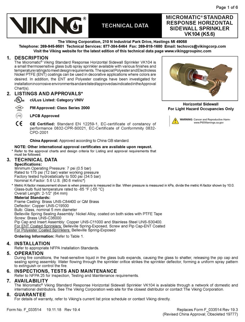
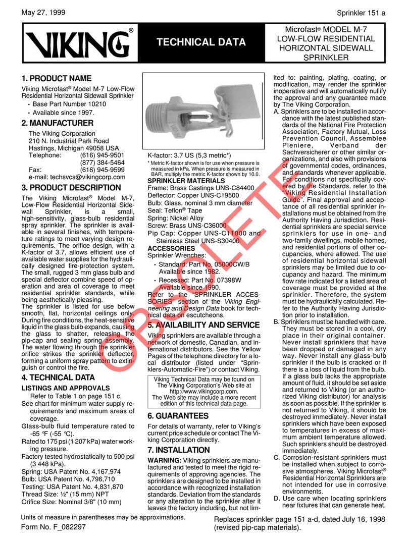
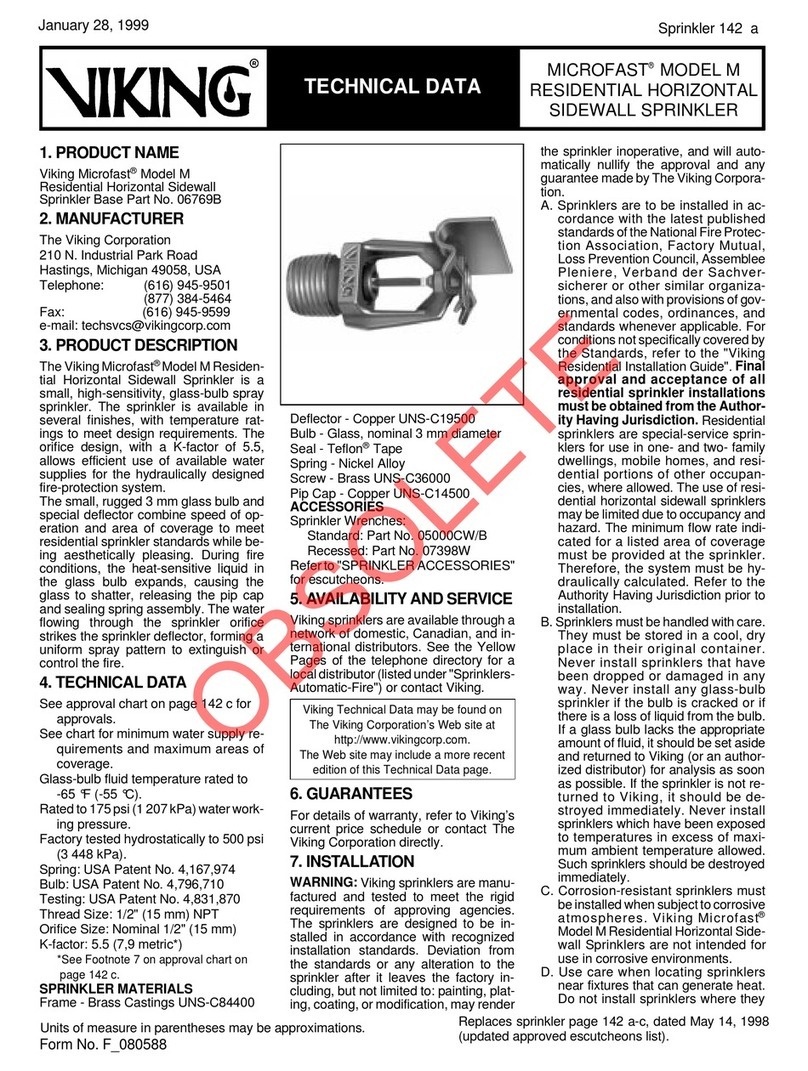
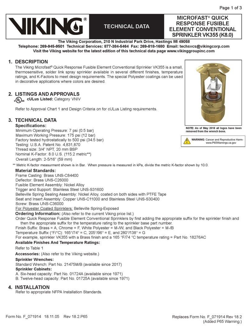
Viking Micromatic®Model M Sidewall
Sprinklers
•HorizontalSidewall(HSW)Sprinkler:
Base Part No. 10224
Available since 1992.
•HorizontalSidewall(HSW)Sprinkler :
Base Part No. 09126
(No Listings or Approvals.)
Available since 1994.
•Vertical Sidewall (VSW) Sprinkler:
Base Part No. 10226
Available since 1992.
•Vertical Sidewall (VSW) Sprinkler:
Base Part No. 09127
(No Listings or Approvals.)
Available since 1994.
2. MANUFACTURER
THE VIKING CORPORATION
210 N. Industrial Park Road
Hastings, Michigan 49058 U.S.A.
Telephone:(616) 945-9501
(877) 384-5464
Fax:(616) 945-9599
e-mail: [email protected]m
3. PRODUCT DESCRIPTION
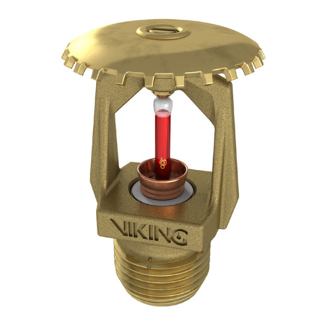
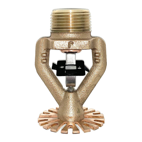
The Viking Micromatic ® Model M Side-
wall Sprinkler is a small,
thermosensitive glass-bulb spray sprin-
kler. The sprinkler consists of a small
frame and rugged 5 mm glass-bulb, and
isavailableasahorizontalsidewalloras
a vertical sidewall style that is designed
for installation in either the upright or
pendent position.
Micromatic ® Model M Sidewall Sprin-
klersareavailablewithfinishesandtem-
perature ratings to meet design require-
ments. Used in conjunction with one of
thevariouscorrosion-resistantcoatings,
the units provide protection against
many corrosive environments. In addi-
tion, the special polyester or Teflon ®
coatings can be used in decorative ap-
plications.
Duringfireconditions,theheat-sensitive
liquidinthe glassbulbexpands, causing
the bulb to shatter, releasing the pip cap
and sealing spring assembly. Water
flowing through the sprinkler orifice
strikes the sprinkler deflector, forming a
uniform spray pattern to extinguish or
control the fire.
Micromatic ® Model M Sidewall Sprin-
klers may be ordered and/or used used
as open sprinklers (glass bulb and
pip-cap assembly removed) on deluge
systems.
4. TECHNICAL DATA
LISTINGS AND APPROVALS
SeeTable2onpage14candTable3
on page 14 d.
Glass-bulb fluid temperature rated to
-65° F (-55° C).
Ratedto175psi(1207kPa)waterwork-
ing pressure.
Factorytestedhydrostaticallyto500psi
(3 448 kPa).
Minimum operating pressure: 7 psi
(48,3 kPa)
Spring: USA Patent No. 4,167,974
MATERIALS
Frame: Brass Castings UNS-C84400
Vertical Deflector: Brass UNS-C26000
Horizontal Deflector: Copper
UNS-C19500.
Bulb: Glass, nominal 5 mm diameter
Seal: Teflon®Tape
Spring: Nickel Alloy
Note: Units of measure in parentheses may be approximations.
Form No. F_ 072198
Sprinkler 14 a
TECHNICAL DATAMICROMATIC®
MODEL M SIDEWALL
SPRINKLERS
April 29, 1999
Replacessprinklerpage14a-d,datedAugust3,1998
(added Part Numbers 09126 and 09127).
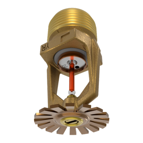
Micromatic®Model M
Vertical Sidewall Sprinkler
(upright shown)
Sprinkler
Temperature
Classification
Nominal
Sprinkler
Temp. Rating
(Fusing Point)
Ceiling Temperature at Sprinkler
Bulb Color 3
Max. Ambient
Temp. Allowed1Max. Recommended
Ambient Temp. 2
Ordinary135 °F (57 °C)115 °F (46 °C)100 °F (38 °C)Orange
Ordinary155 °F (68 °C)135 °F (57 °C)100 °F (38 °C)Red
Intermediate175 °F (79 °C)155 °F (68 °C)150 °F (65 °C)Yellow
Intermediate200 °F (93 °C)180 °F (82 °C)150 °F (65 °C)Green
High286 °F (141 °C)266 °F (130 °C)225 °F (107 °C)Blue
Extra High360 °F (182 °C)340 °F (171 °C)300 °F (149 °C)Mauve
Sprinkler Finishes:Brass, Bright Brass, Chrome-Enloy (patents pending), White Polyes-
ter, Black Polyester, and Black Teflon 
Corrosion-Resistant Coatings 4:Polyester and Teflon in all temperatures, and Wax
Coated Brass and Wax over Polyester in the following temperatures:
135 °F (57 °C) White Wax175 °F (79 °C) Dark Brown Wax
155 °F (68 °C) Light Brown Wax200 °F (93 °C) Dark Brown Wax
Footnotes
1Based on National Fire Prevention and Control Administration Contract No. 7-34860.
2 Based on NFPA-13. Other limits may apply, depending on fire loading, sprinkler location,
and other requirements of the Authority Having Jurisdiction. Refer to specific installation
standards.
3The temperature rating is stamped on the deflector.
4 The corrosion-resistant coatings have passed the standard corrosion test required by the
approvingagenciesindicated(refertoTable2onpage14candTable3onpage14d).These
tests cannot and do not represent all possible corrosive environments. Prior to installation,
verify through the end-user that the coatings are compatible or suitable for the proposed
environment.Thecoatingsindicatedareappliedtotheexposedexteriorsurfacesonlyand,
therefore,cannotbeusedasopen sprinklers.NotethatthespringisexposedontheTeflon 
and Polyester coated sprinklers.
Table 1
Micromatic 
Model M Horizontal
Sidewall Sprinkler
OBSOLETE
Screw: Brass UNS-C36000
Pip Cap:
•For Part Number 10224: Bronze
UNS-C31600
•Forall others: Copper UNS-C11000
and Stainless Steel UNS-S30400
Polyester Coated Sprinklers:
Spring: Nickel Alloy, exposed
Screw: Brass UNS-C36000
Painted white for appearance only.
Pip Cap:
•For Part Number 10224: Bronze
UNS-C31600
•For all others: Copper UNS-C11000
and Stainless Steel UNS-S30400
Teflon®Coated Sprinklers:
Screw: Brass UNS-C36000
Painted black for appearance only.
Spring: Nickel Alloy, exposed
Pip Cap: ( Teflon®coated)
•For Part Number 10224: Bronze
UNS-C31600
•For all others: Copper UNS-C11000
and Stainless Steel UNS-S30400
ACCESSORIES
Sprinkler Wrenches:
A. Standard Micromatic ®Wrench:
Part No. 05000CW/B
Available since 1982.
B. Wrench for coated and recessed
Micromatic Sprinklers:
Part No. 07398W
Available since 1990.
Refer to “Sprinkler Accessories” section
of the Viking Engineering and Design
Databook for other accessories.
AVAILABLE FINISHES
Chrome-Enloy ®, Brass, Bright Brass,
White Polyester, Black Polyester, Black
Teflon ®,andWax-CoatedBrassorPoly-
ester
5. AVAILABILITY AND SERVICE
Vikingsprinklers are availablethrough a
network of domestic, Canadian, and in-
ternational distributors. See the Yellow
Pages of the telephone directory for a
local distributor (listed under “Sprin-
klers-Automatic-Fire”)orcontactViking.
6. GUARANTEES
For details of warranty, refer to Viking’s
currentlistpricescheduleorcontactThe
Viking Corporation directly.
7. INSTALLATION
WARNING:Viking sprinklers are manu-
factured and tested to meet the rigid re-
quirements of the approving agencies.
The sprinklers are designed to be in-
stalled in accordance with recognized
installation standards. Deviation from
the standards or any alteration to the
sprinkler after it leaves the factory in-
cluding, but not limited to: painting, plat-
ing,coating,or modification,mayrender
the sprinkler inoperative and will auto-
matically nullify the approvals and any
guaranteemadebyTheVikingCorpora-
tion. Refertothe AuthorityHavingJuris-
diction prior to installation.
A.Sprinklers aretobe installedin accor-
dance with the latest published stan-
dards of the National Fire Protection
Association, Factory Mutual, Loss
Prevention Council, Assemblee
Pleniere, Verband der
Sachversicherer or other similar or-
ganizations, and also with the provi-
sions of governmental codes, ordi-
nances, and standards, whenever
applicable.
B.Sprinklersmustbehandledwithcare.
They must be stored in a cool, dry
place in their original shipping con-
tainer. Never install sprinklers that
havebeendropped,damaged,or ex-
posed to temperatures in excess of
the maximum ambient temperature
allowed. Never install any glass-bulb
sprinkler if the bulb is cracked or if
there is a loss of liquid from the bulb.
If a glass bulb lacks the appropriate
amountoffluid, it shouldbeset aside
and returned to Viking (or an autho-
rized Viking distributor) for analysis
assoonaspossible.If thesprinkleris
not returned to Viking, it should be
destroyed immediately.
C. Corrosion-resistant sprinklers must
be installed when subject to corro-
sive atmospheres. When installing
corrosion-resistant sprinklers, take
care not to damage the corro-
sion-resistant coating. Use only the
special wrench designed for install-
ing coated and recessed Microfast
Sprinklers (any other wrench may
damage the unit). DO NOT use the
sprinkler deflector to start or thread
the sprinkler into a fitting.
D. Use care when locating sprinklers
near fixtures that can generate heat.
Do not install sprinklers where they
will be exposed to temperatures that
exceed the maximum recommended
ambient temperature for the temper-
ature rating used.
E. Before installation, be sure to have
the appropriate sprinkler model and
style, with the proper orifice size,
temperature rating, and response
characteristics. The sprinkler must
beinstalledafterthe pipingisinplace
to prevent mechanical damage.
1. Install escutcheon (if used), which
is designed to thread onto the ex-
ternalthreads ofthe sprinkler.Re-
fer to the “Sprinkler Acces-
sories”section of the Viking Engi-
neering and Design Databook for
technical data describing ap-
provedescutcheonsandotherac-
cessories.
2. Apply a small amount of pipe-joint
compound or tape to the external
threads of the sprinkler only, tak-
ing care not to allow a build-up of
compound in the sprinkler inlet.
3. Install the sprinkler on the piping
usingthe specialsprinkler wrench
only, taking care not to
over-tighten or damage the sprin-
kleroperating parts. DONOTuse
the deflector to start or thread the
sprinkler into a fitting.
F. After installation, the entire sprinkler
systemmustbetestedinaccordance
with the recognized installation stan-
dards. The test is applied after the
sprinklerinstallationtoensurethatno
damagehasoccurredtothesprinkler
during shipping and installation, and
to make sure the sprinkler has been
properly tightened. If a thread leak
occurs, normally the sprinkler must
be removed, new pipe-joint com-
pound or tape applied, and then rein-
stalled. This is due to the fact that
when the joint seal is damaged, the
sealing compound or tape is washed
out of the joint. Air testing the sprin-
kler piping prior to testing with water
may be considered in areas where
leakage during testing must be pre-
vented. Refer to the appropriate
technicaldataand the AuthorityHav-
ing Jurisdiction prior to air testing the
sprinkler piping.
G. Sprinklers must be protected from
mechanical damage. Wet-pipe sys-
tems must be provided with ade-
quate heat. Do not install vertical
sidewallsprinklersinthependent po-
sitionondrysystemsinareassubject
to freezing. When installing vertical
sidewall sprinklers on dry systems in
heated areas, refer to the Installation
Guides and the Authority Having Ju-
risdiction.
Sprinkler 14 b
TECHNICAL DATAMICROMATIC®
MODEL M SIDEWALL
SPRINKLERS
April 29, 1999
Viking Technical Data may be found on
The Viking Corporation’s Web site at
http://www.vikingcorp.com.
The Web site may include a more recent
edition of this Technical Data page.
OBSOLETE
8. MAINTENANCE
NOTICE: The owner is responsible for
maintaining the fire-protection system
and devices in proper operating condi-
tion. For minimum maintenance and in-
spection requirements, refer to the ap-
propriate National Fire Protection Asso-
ciation’s pamphlet that describes care
and maintenance of sprinkler systems.
In addition, the Authority Having Juris-
diction may have additional mainte-
nance, testing, and inspection require-
ments that must be followed.
A. Sprinklers must be inspected on a
regular basis for corrosion, mechani-
cal damage, obstructions, paint, etc.
The frequency of the inspections
may vary due to corrosive atmo-
spheres, water supplies, and activity
around the device.
B. Sprinklers that have been painted or
mechanically damaged must be re-
placed immediately. Standard re-
sponse sprinklers showing signs of
corrosion shall be tested and/or re-
placed immediately as required.
MicromaticSprinklers that are 50
years old shall be tested and/or re-
placed immediately as required.
Sprinklersthathaveoperatedcannot
bereassembled or re-used,but must
be replaced. When replacing sprin-
klers, use only new sprinklers.
C. The sprinkler discharge pattern is
critical for proper fire protection.
Therefore, nothing should be hung
from, attached to, or otherwise ob-
struct the discharge pattern.All ob-
structions must be immediately re-
moved or, if necessary, additional
sprinklers installed.
Sprinkler14c
April 29, 1999
For listings and approvals of assemblies for recessed installations, see Table 3 on page 14 d.
Approval Chart
Micromatic Model M Sidewall Sprinkler
5 mm Glass Bulb, Standard Response
Installed with Standard Surface-Mounted Escutcheon
Standard Orifice
Thread SizeNominal
OrificeDescriptionNominal
K-factor 7Overall
LengthListings and Approvals 2,3
N.P.T.B.S.P.InchesmmStyleBase P/N 1U.S.metricInchesmmUL4ULC 4FM5LPCB
1/2"15 mm1/215Horizontal102245.57,92.564A1, A4, D6A1, C4A2, C3A2, C3, C5
1/2"15 mm1/215Vertical U/P102265.57,92.358A1, A4, D6A1, C4A2, C3--
Small Orifice
--10 mm3/810Horizontal09126--5,82.43761,9--------
--10 mm3/810Vertical U/P09127--5,82.18855,58--------
Approved Temperatures
A - 135 °F (57 °C), 155 °F (68 °C), 175 °F (79 °C),
200 °F (93 °C), 286 °F (141°C), and 360 °F (182 °C)
B - 135 °F (57 °C), 155 °F (68 °C), 175 °F (79 °C),
200 °F (93 °C), and 286 °F (141°C)
C - 135 °F (57 °C), 155 °F (68 °C), 175 °F (79 °C),
and 200 °F (93 °C)
D - 286 °F (141°C)
Approved Finishes
1 - Brass, Bright Brass, Chrome-Enloy , White Polyester 6, Black
Polyester 6, and Black Teflon 6
2 - Brass, Bright Brass, and Chrome-Enloy 
3 - Wax-Coated Brass (corrosion resistant)
4 - Wax-Coated Brass and Wax over Polyester (corrosion resistant)
5 - White Polyester and Black Polyester
6 - 200 °F (93 °C) Wax Coating (corrosion resistant); maximum
ambient temperature at ceiling = 150 °F (65 °C)
Footnotes
1Base part number is shown. For complete part number, see Viking's current price schedule.
2This table shows the listings and approvals available at the time of printing. Other approvals are in process. Check with the manufacturer
for any additonal approvals.
3Acceptance for use, City of New York Board of Standards and Appeals, is pending.
4ULandULCListedforLightHazardoccupancies.Locatehorizontalsidewallsprinklersw ithdeflectors4"to12"(102mmto304mm)below
ceilings, and 4" to 6" (102 mm to 152 mm) from walls.
Exception:Horizontalsidewallsprinklersmaybeinstalledwiththedeflectorslessthan4"(102mm)f romthewallinwhichtheyareinstalled.
Viking vertical sidewall sprinklers may be installed pendent or upright. Align top of hori zontal sidewall deflectors parallel to the ceiling or
roof.Locateverticalsidewallsprinklerswithdeflectors4"to6"(102mmto152mm)fromw allsand4"to6"(102mmto152mm)belowceilings.
Exception: Pendent verticalsidewall sprinklers may be located with the deflectors less than 4" (102 m m) below theceiling in which they are
installed.
5Approved for Light Hazard occupancies. Located horizontal sidewall sprinklers and vertical sidewall sprinklers with deflectors 4" to 6"
(102mmto152mm)belowceilings,and4"to6"(102mmto152mm)fromwalls.Aligntopofhori zontalsidewalldeflectorsparalleltothe
ceiling or roof.
Exception:Horizontalsidewallsprinklersmaybeinstalledwiththedeflectorslessthan4"(102mm)f romthewallinwhichtheyareinstalled.
Vikingverticalsidewallsprinklersmaybeinstalledpendentorupright.Locateverticalsidewallsprinklerswithdeflector4"to6"(102mmto
152 mm) from walls and 4" to 6" (102 mm to 152 mm) below ceilings.
Exception:Pendent verticalsidewall sprinklers may be located with the deflectors less than 4" (102 mm) belowthe ceiling in which they are
installed.
6 UL and ULC Listed as corrosion-resistant sprinklers.
7MetricK-Factor shown isfor use whenpressure is measuredin kPa. Whenpressure is measuredin BAR, multiply the metricK-Factor shown
by 10.0.
Table 2
KEY
See Row A See Row 1
of Approved of Approved
Temp.ChartA1FinishChart
TECHNICAL DATAMICROMATIC®
MODEL M SIDEWALL
SPRINKLERS
OBSOLETE
D. When replacing existing sprinklers,
the system must be removed from
service. Refertotheappropriatesys-
tem description and/or valve instruc-
tions. Prior to removing the system
from service, notify all Authorities
Having Jurisdiction. Consideration
should be given to employment of a
fire patrol in the affected area.
1. Remove the system from service,
drain all water, and relieve all
pressure on the piping.
2. Using the al sprinkler wrench, re-
move the old sprinkler and install
the new unit. Care must be taken
to ensure that the replacement
sprinkler is the proper model and
style, and has the appropriate ori-
fice size, temperature rating, and
response characteristics. A fully
stocked spare sprinkler cabinet
should be provided for this pur-
pose.
3. Place the system back in service
and secure all valves. Check and
repair all leaks.
E. Sprinkler systems that have been
subjected to a fire must be returned
to service as soon as possible. The
entire system must be inspected for
damage,andrepaired or replaced as
necessary.Sprinklersthathavebeen
exposed to corrosive products of
combustion of high ambient temper-
atures,buthavenotoperated,should
be replaced. Refer to the Authority
Having Jurisdiction for minimum re-
placement requirements.
TECHNICAL DATAMICROMATIC®
MODEL M SIDEWALL
SPRINKLERS
April 29, 1999
Sprinkler 14 d
Form No. F_072198
Approval Chart
Micromatic Model M Sidewall Sprinkler
5 mm Glass Bulb, Standard Response
Recessed with Viking Model E-1 Recessed Escutcheon
Standard Orifice
Thread SizeNominal
OrificeDescriptionNominal
K-factor 6Overall LengthListings and Approvals 2
N.P.T.B.S.P.InchesmmStyleBase P/N 1U.S.metricInchesmmUL 4ULC4NYC 3,4LPCB
1/2"15 mm1/215Horizontal102245.57,92.564B1, B2B1, B2B1, B2--
1/2"15 mm1/215Vertical U/P102265.57,92.358B1, B2------
Small Orifice
--10 mm3/810Horizontal09126--5,82.43761,9--------
--10 mm3/810Vertical U/P09127--5,82.18855,58--------
Installed with Viking Model F-1 Adjustable Escutcheon
Standard Orifice
Thread SizeNominal
OrificeDescriptionNominal
K-factor 6Overall LengthListings and Approvals 2
N.P.T.B.S.P.InchesmmStyleBase P/N 1U.S.metricInchesmmUL 4ULC4NYC 3,4LPCB
1/2"15 mm1/215Horizontal102245.57,92.564A1, B2B1, B2B1, B2--
1/2"15 mm1/215Vertical U/P102265.57,92.358A1, B2------
Small Orifice
--10 mm3/810Horizontal09126--5,82.43761,9--------
--10 mm3/810Vertical U/P09127--5,82.18855,58--------
Approved Temperatures
A - 135 °F (57 °C), 155 °F (68 °C), 175 °F (79 °C),
200 °F (93 °C), 286 °F (141°C), and 360 °F (182 °C)
B - 135 °F (57 °C), 155 °F (68 °C), 175 °F (79 °C), and
200 °F (93 °C)
Approved Finishes
1 - Brass, Bright Brass, Chrome-Enloy , White Polyester 5, Black
Polyester 5, and Black Teflon 5
2 - Wax-Coated Brass and Wax over Polyester (corrosion resistant)
Footnotes
1Base part number is shown. For complete part number, see Viking's current price schedule.
2This table shows the listings and approvals available at the time of printing. Other approv als are in process. Check with the manufacturer for
any additonal approvals.
3Acceptance for use, City of New York Board of Standards and Appeals, is pending.
4ULandULCListedforLightHazardoccupancies.Locatehorizontalsidewallsprinklersw ithdeflectors4"to12"(102mmto304mm)below
ceilings, and 4" to 6" (102 mm to 152 mm) from walls. Align top of horizontal sidewall deflectors parallel to the ceiling or roof.
Exception:Horizontalsidewallsprinklersmaybeinstalledwiththedeflectorslessthan4"(102mm)f romthewallinwhichtheyareinstalled.
Viking vertical sidewall sprinklers may be installed pendent or upright. Locate vertical sidewall sprinklers with deflectors 4" to 6" (102 mm to
152 mm) from walls and 4" to 6" (102 mm to 152 mm) below ceilings.
Exception:Pendentverticalsidewallsprinklersmaybelocatedwiththedeflectorslessthan4"(102m m)belowtheceilinginwhichtheyarein
stalled.
5 UL and ULC Listed as corrosion-resistant sprinklers.
6MetricK-Factor shown isfor use when pressureis measured inkPa. When pressureis measuredin BAR, multiplythe metric K-Factorshown
by 10.0. Table 3
KEY
See Row A See Row 1
of Approved of Approved
Temp.ChartA1FinishChart
Replacessprinklerpage14a-d,datedAugust3,1998
(added Part Numbers 09126 and 09127).
OBSOLETE

This manual suits for next models

4

Other Viking Irrigation System manuals

Viking MICROFAST M-4 Instruction manual

Viking

Viking MICROFAST M-4 Instruction manual

Viking FREEDOM VK479 Instruction manual

Viking

Viking FREEDOM VK479 Instruction manual

Viking VK2001 Instruction manual

Viking

Viking VK2001 Instruction manual

Viking VK2002 Instruction manual

Viking

Viking VK2002 Instruction manual

Viking MICROFAST VK332 Instruction manual

Viking

Viking MICROFAST VK332 Instruction manual

Viking MICROFAST VK307 Instruction manual

Viking

Viking MICROFAST VK307 Instruction manual

Viking HORIZON MIRAGE Instruction manual

Viking

Viking HORIZON MIRAGE Instruction manual

Viking FREEDOM VK472 Instruction manual

Viking

Viking FREEDOM VK472 Instruction manual

Viking VK3101 Instruction manual

Viking

Viking VK3101 Instruction manual

Viking VK3021 Instruction manual

Viking

Viking VK3021 Instruction manual

Viking K80 Instruction manual

Viking

Viking K80 Instruction manual

Viking VK2022 Instruction manual

Viking

Viking VK2022 Instruction manual

Viking V-HIP Instruction manual

Viking

Viking V-HIP Instruction manual

Viking FREEDOM VK466 Instruction manual

Viking

Viking FREEDOM VK466 Instruction manual

Viking MICROFAST VK354 Instruction manual

Viking

Viking MICROFAST VK354 Instruction manual

Viking SIN VK500 Instruction manual

Viking

Viking SIN VK500 Instruction manual

Viking VK108 Instruction manual

Viking

Viking VK108 Instruction manual

Viking FREEDOM VK484 Instruction manual

Viking

Viking FREEDOM VK484 Instruction manual

Viking VK3502 Instruction manual

Viking

Viking VK3502 Instruction manual

Viking MICROFAST VK310 Instruction manual

Viking

Viking MICROFAST VK310 Instruction manual

Viking MICROFAST M Instruction manual

Viking

Viking MICROFAST M Instruction manual

Viking VK535 Instruction manual

Viking

Viking VK535 Instruction manual

Viking FREEDOM VK486 Instruction manual

Viking

Viking FREEDOM VK486 Instruction manual

Viking MicrofastHP VK317 Instruction manual

Viking

Viking MicrofastHP VK317 Instruction manual

Popular Irrigation System manuals by other brands

Tyco Fire Protection Products LD quick start guide

Tyco Fire Protection Products

Tyco Fire Protection Products LD quick start guide

Rain Bird MAXI PAW manual

Rain Bird

Rain Bird MAXI PAW manual

Reliable MBEC-14 Bulletin

Reliable

Reliable MBEC-14 Bulletin

Reliable F3-80 Series Bulletin

Reliable

Reliable F3-80 Series Bulletin

Cellfast 52-072 user manual

Cellfast

Cellfast 52-072 user manual

Johnson Controls tyco EC-8 Series manual

Johnson Controls

Johnson Controls tyco EC-8 Series manual

Tyco Fire Product CENTRAL BV4 instruction manual

Tyco Fire Product

Tyco Fire Product CENTRAL BV4 instruction manual

Tyco TY-L Series manual

Tyco

Tyco TY-L Series manual

Tyco RAPID RESPONSE Series manual

Tyco

Tyco RAPID RESPONSE Series manual

Tyco Gem PSN 56-701-9-010 manual

Tyco

Tyco Gem PSN 56-701-9-010 manual

Tyco Rapidresponse LFII Series manual

Tyco

Tyco Rapidresponse LFII Series manual

Tyco EC-5 Series manual

Tyco

Tyco EC-5 Series manual

Autopot 8Pot system Set-up guidelines

Autopot

Autopot 8Pot system Set-up guidelines

Hunter Institutional Series manual

Hunter

Hunter Institutional Series manual

Reliable F1XLH Series quick start guide

Reliable

Reliable F1XLH Series quick start guide

Toro NO FOUND TMC-424E Quick reference guide

Toro

Toro NO FOUND TMC-424E Quick reference guide

SNOWJOE AQUAJOE SJI-OMS20 manual

SNOWJOE

SNOWJOE AQUAJOE SJI-OMS20 manual

Tyco Fire Product TY-B Series manual

Tyco Fire Product

Tyco Fire Product TY-B Series manual

manuals.online logo
manuals.online logoBrands
  • About & Mission
  • Contact us
  • Privacy Policy
  • Terms and Conditions

Copyright 2025 Manuals.Online. All Rights Reserved.