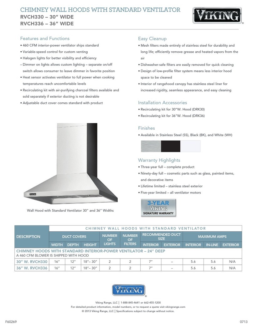
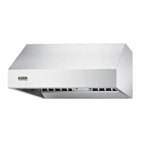
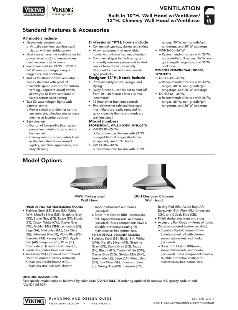
manuals.online logo
Brands
  1. Home
  2. •
  3. Brands
  4. •
  5. Viking
  6. •
  7. Ventilation Hood
  8. •
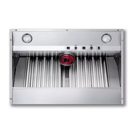
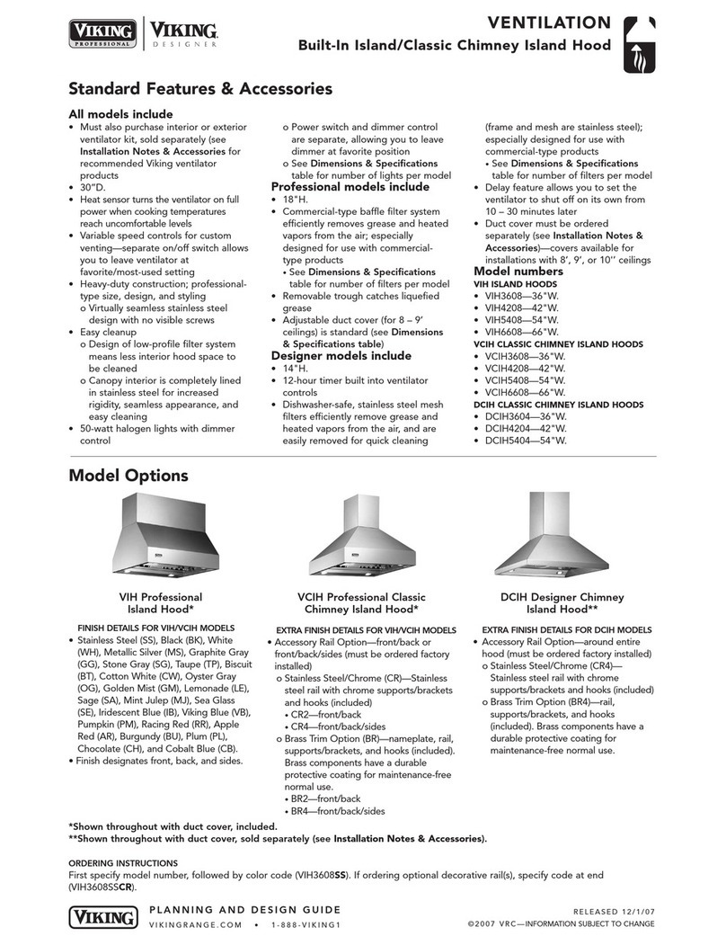
  9. Viking VCIH3608 User manual

Viking VCIH3608 User manual

F20470 (070907J)
UL
C
UL
Viking Installation Guide
Professional Hoods
Viking Range Corporation
111 Front Street
Greenwoo , Mississippi 38930 USA
(662) 455-1200
For pro uct information,
call 1-888-VIKING1 (845-4641)
or visit the Viking Web site at
vikingrange.com
Table of Contents
Warnings & Important Information
________________________________________________________ 3-
4
VWH 10”H. Wall Hoo s w/Stan ar Ventilator 24”, 30”, & 36”
Dimensions & Specifications _____________________________________________________ 5
Clearance Dimensions ___________________________________________________________ 6
Interior Ventilator Dimensions ____________________________________________________ 7
VWH 18”H. 24”/27” Deep Wall Hoo s 24”, 30”, 36”, 42”, 48”, 54”, 60”, & 66”
Dimensions & Specifications ______________________________________________________ 8
Clearance Dimensions _____________________________________________________________ 9
Interior Ventilator Dimensions _____________________________________________________ 10
Exterior Ventilator Dimensions ___________________________________________________ 11
VCWH Chimney Wall Hoo s 30”, 36”, 42”, 48”, 54”, 60”, & 66”
Dimensions & Specifications _____________________________________________________ 12
Clearance Dimensions __________________________________________________________ 13
Interior Ventilator Dimensions ___________________________________________________ 14
Exterior Ventilator Dimensions ___________________________________________________ 15
VIH Islan Hoo s 36”, 42”, 54”, & 66”
Dimensions & Specifications _____________________________________________________ 16
Clearance Dimensions___________________________________________________________ 17
Interior Ventilator Dimensions ___________________________________________________ 18
Exterior Ventilator Dimensions ___________________________________________________ 19
VCIH Chimney Islan Hoo s 36”, 42”, 54”, & 66”
Dimensions & Specifications _____________________________________________________ 20
Clearance Dimensions___________________________________________________________ 21
Interior Ventilator Dimensions ___________________________________________________ 22
Exterior Ventilator Dimensions ___________________________________________________ 23
Planning Information________________________________________________________________ 24
Installation Proce ures
Installation (VWH 10”H. Wall Hoo s w/Stan ar Ventilator) __________________________ 25
Duct Cover Option (VWH 10”H. Wall Hoo s w/Stan ar Ventilator)___________________ 27
Installation (VWH 10”H. Wall Hoo s w/Recirculating Kit) _____________________________ 27
Installation (VWH 18”H. Wall & VCWH Chimney Wall Hoo s) ________________________ 30
Duct Cover Option (VWH 18”H. Wall Hoo s)_______________________________________ 31
Duct Cover Option (VCWH Chimney Wall Hoo s) __________________________________ 32
Installation (VIH/VCIH Islan Hoo s) ______________________________________________ 33
Wiring Diagram ____________________________________________________________________ 35
Service & Registration_______________________________________________________________ 36
3
IMPORTANT–Please Read and Follow!
NOTE:
If installing hood with warming shelf panel,
install warming shelf panel first.
IMPORTANT PLEASE READ AND FOLLOW
• Before beginning, please rea these instructions
completely an carefully.
• Do not remove permanently affixe labels, warnings, or
plates from the pro uct. This may voi the warranty.
• Please observe all local an national co es an
or inances. If no local co es are applicable, wire in
accor ance with the National Electrical Co e,
ANSI/NFPA 70-latest e ition.
• Out oor approve mo els shoul be installe in a
covere non-enclose area an shoul be protecte
from the elements as much as possible.
• The installer shoul leave these instructions with the
consumer who shoul retain for local inspector’s use an
for future reference.
• Check with a qualifie an traine installer or local co es
for makeup air requirement, if any.
This hoo is for resi ential installation only an is not
esigne for installation over a commercial pro uct. Make
sure power is off at the main circuit breaker or fuse box
before making connections. To avoi risk of fire, electric
shock, or injury to persons, turn off the electricity to the
hoo from the power supply before servicing or cleaning.
Viking hoo s are equippe with variable spee control
blowers. These units will not function with a single spee
ventilator. All Viking Range ventilator kits are esigne
specifically for use with Viking Range hoo s. Use of any
non-Viking Range ventilator kit will voi the hoo warranty.
Viking hoo s are equippe with the variable spee
controls for blowers. These units will not function with a
single spee ventilator. All Viking ventilator kits are
esigne specifically for use with Viking hoo s. Use of any
non-Viking ventilator kit will voi the hoo warranty.
READ AND SAVE THESE INSTRUCTIONS WARNING
TO REDUCE THE RISK OF A RANGETOP
GREASE FIRE:
1. Never leave surface units unatten e at high
setting. Boilovers cause smoking an greasy
spillovers that may ignite. Heat oils slowly on
low or me ium settings.
2. Always turn hoo ON when cooking at high
heat or when cooking flaming foo s. (i.e.
Crepes suzette, Cherries jubilee, Peppercorn
beef flambé).
3. Clean ventilating fans frequently. Grease shoul
not be allowe to accumulate on fan or filter.
4. Use proper pan size. Always use cookware
appropriate for the size of the surface element.
TO REDUCE THE RISK OF FIRE, ELECTRICAL
SHOCK, OR INJURY TO PERSONS, OBSERVE
THE FOLLOWING:
1. Installation work an electrical wiring must be
one by qualifie person(s) in accor ance with
all applicable co es an stan ar s, inclu ing
fire-rate construction.
2. Sufficient air is nee e for proper combustion
an exhausting of gases through the flute
(chimney) of fuel burning equipment to prevent
back rafting. Follow the heating equipment
manufacturer’s gui eline an safety stan ar s
such as those publishe by the National Fire
Protection Association (NFPA), an the
American Society for Heating, Refrigeration an
Air Con itioning Engineers (ASHRAE), an the
local co e authorities.
3. When cutting of rilling into wall or ceiling, o
not amage electrical wiring an other hi en
utilities.
4. Ducte fans must always be vente to the out oors.
5. WARNING!: To re uce risk of fire, use only
metal uctwork
6. CAUTION!: To re uce risk of fire an to
properly exhaust air, be sure to uct air outsi e.
Do not vent exhaust air into spaces within walls
or ceilings, or into attics, crawl spaces, or
garages.
7. CAUTION!: To Re uce the Risk of Fire an
Electric Shock, Install this rangehoo only with
remote blower mo els manufacture by Viking,
mo el numbers – DEV900/DEV1200,
VEV900/VEV1200, OR DEV1500, VEV1500 or
integral blowers manufacture by Viking, mo el
numbers – DIV300, DIV440, DIV600, DIV800,
DIV1200, VIV300, VIV600, or VIV1200. NOTE –
Please refer insi e for specific canopy/blower
combinations.
WARNING
WARNING
To reduce the risk of fire, electric shock, or injury
to persons, observe the following:
• Use this unit only in the manner inten e by the
manufacturer. If you have any questions, contact
the manufacturer.
• Before servicing or cleaning unit, switch power off
at service panel an lock service panel to prevent
power from being switche on acci entally. When
the service isconnecting means cannot be locke ,
securely fasten a prominent warning evice, such
as a tag, to the service panel.
5
IMPORTANT–Please Read and Follow!
4
WARNING
TO REDUCE THE RISK OF FIRE,
ELECTRICAL SHOCK, OR INJURY
TO PERSONS
Rangehoo s must be installe with
the ventilators that are specifie on
their carton in icating suitability with
this mo el. Other ventilators cannot be substitute .
CAUTION
For general ventilating use only. Do not use to
exhaust hazar ous or explosive materials an
vapors.
WARNING
To reduce the risk of injury to persons in the
event of a rangetop grease fire, observe the
following. (Based on “Kitchen Firesafety Tips,”
published by NFPA.)
1. SMOTHER FLAMES with a close fitte li , cookie
sheet, or metal tray, then turn off the burner. BE
CAREFUL TO PREVENT BURNS. If the flames o
not go out imme iately, EVACUATE AND CALL
THE FIRE DEPARTMENT.
2. NEVER PICK UP A FLAMING PAN. You may be
burne .
3. DO NOT USE WATER, inclu ing wet ishcloths or
towels a violent steam explosion will result.
4. Use an extinguisher ONLY if
• You know it is a Class ABC extinguisher, an you
alrea y know how to operate it.
• The fire is small an containe in the area where
it starte .
• The fire epartment is being calle .
• You can fight the fire with your back to an exit.
21”
(53.3cm)
A
10”
(25.4cm)
12”
(30.5cm)
A (Hood width)
24”W. 23-7/8“ (60.6 cm)
30”W. 29-7/8“ (76.2 cm)
36”W. 35-7/8” (91.1 cm)
6”
(15.2cm)
Dimensions & Specifications
(VWH 10”H. Wall Hoo s w/Stan ar Ventilator 24”, 30”, & 36”)
* Disregard when using recirculating kits.
4 0 CFM blower is shipped with hood.
VWH 10 H. Wall Hoods w/Standard Ventilator
Description 24 30 36
Duct cover wi th 23-7/8” (60.6 cm) 29-7/8” (75.9 cm) 35-7/8” (91.1 cm)
Duct cover epth 12” (30.5 cm)
Duct cover height 12” (30.5 cm)
Number of lights 2
Number of filters 2
Heat lamps N/A
Interior ventilator kit 460 CFM Standard
Interior uct size* 7” (17.8 cm)
Interior—Maximum amps 5.6
NOTE: Optional duct cover sold separatel .
6
Clearance Dimensions
7
* NOTE: When installing with a 24” high-shelf,
the 27” (68.6 cm) max. dimensions must be used.
24”min.
(61.0cm)
to
27”max.*
(68.6cm)
60”min.
(152.4 cm)
to
63”max.
(160.0 cm)
36”
(91.4cm)
Interior Ventilator Dimensions
A
B
C
D
18”
(4.6 cm)
3-7/8”
(9.8 cm)
3-4”
(1.9 cm)
7” (17.8 cm) dia.
duct location
Electrical
hookup
1/2”
(1.3 cm)
4”
(10.2 cm)
3-1/2”
(8.9 cm)
A
24”W. 23-7/8” (60.6 cm)
30”W. 29-7/8” (75.9 cm)
36”W. 35-7/8” (91.1 cm)
B
24”W. 5-1/4” (13.3 cm)
30”W. 8-1/4” (20.9 cm)
36”W. 11-1/4” (28.6 cm)
C
24”W. 11-15/16” (30.3 cm)
30”W. 14-15/16” (37.9 cm)
36”W. 17-15/16” (45.6 cm)
D
24”W. 5/8” (1.6 cm)
30”W. 3-5/8” (9.2 cm)
36”W. 6-5/8” (16.8 cm)
460 CFM Interior Ventilator Installation
Top View
(VWH 10”H. Wall Hoo s w/Stan ar Ventilator)
9
Dimensions & Specifications
8
B
A
18”
(45.7 cm)
12”
(30.5 cm)
6”
(15.2 cm)
A (Hood width)
24”W. 23-7/8“ (60.6 cm)
30”W. 29-7/8“ (76.2 cm)
36”W. 35-7/8” (91.1 cm)
42”W. 41-7/8” (106.4 cm)
48“W. 47-7/8” (121.6 cm)
54”W. 53-7/8” (136.8 cm)
60”W. 59-7/8” (152.1 cm)
66”W. 65-7/8” (167.3 cm)
B (Hood depth)
24”D. 24” (61.0 cm)
27”D. 27” (68.6 cm)
(VWH 18”H. 24” Deep Wall Hoo s 24”, 30”, 36”, 42”, 48”, 54”, 60”, & 66”)
(VWH 18”H. 27” Deep Wall Hoo s 30”, 36”, 42”, 48”, 54”, 60”, & 66”)
* A 1,200 CFM interior- or exterior-power ventilator should be used when installed over range/rangetop
with gas char-grill. Max duct run is 50 ft.
** It is recommended that the 1,500 CFM ventilator be used with longer duct runs. Max duct run is 75 ft.
NOTE: Ma imum amp rating for hoods includes recommended ventilator kit rating; All products must be
hard wired with 2-wire with ground. An interior- or e terior-power ventilator kit must be purchased for
installation with all 18”H. hoods.
30”min.
(76.2cm)
to
36”max.
(91.4cm)
66”min.
(167.6 cm)
to
72”max.
(182.9 cm)
36”
(91.4cm)
Clearance Dimensions
VWH 18 H. Wall Hoods
Description 24 30 36 42 48 54 60 66
Duct cover wi th 23-7/8” 29-7/8” 35-7/8” 41-7/8” 47-7/8” 53-7/8” 59-7/8” 65-7/8”
(60.6 cm) (75.9 cm) (91.1 cm) (106.4 cm) (121.6 cm) (136.8 cm) (152.1 cm) (167.3 cm)
Duct cover epth 12” (30.5 cm)
Duct cover height 12” (30.5 cm)
Number of lights 22 2 23344
Number of filters 22 2 23344
Heat lamps 11 1 12222
Interior ventilator kits VIV300/ VIV300/ VIV300/ VIV600/ VIV1200* VIV1200* VIV1200* VIV1200*
600 600/1200* 600/1200* 1200*
Exterior ventilator kits VEV900/ VEV900/ VEV900/ VEV900/ VEV1200*/ VEV1200*/ VEV1200*/ VEV1200*/
1200* 1200* 1200* 1200* 1500** 1500** 1500** 1500**
Interior uct size 7” 7”/10” 7”/10” 7”/10” 10” 10” 10” 10”
(17.8 cm) (17.8/25.4 cm) (17.8/25.4 cm) (17.8/25.4 cm) (25.4 cm) (25.4 cm) (25.4 cm) (25.4 cm)
Exterior uct size 10” (25.4 cm)
Interior—Maximum amps 5.0/6.2 5.0/6.2/8.7 5.0/6.2/8.7 6.2/8.7 11.1 11.1 11.5 11.5
Exterior—Maximum amps 8.7/6.1 8.7/6.1 8.7/6.1 8.7/6.1 8.4/9.1 8.4/9.1 8.8/9.5 8.8/9.5
(VWH 18”H. Wall Hoo s)
NOTE: Optional duct cover sold separatel .
Exterior Ventilator Dimensions
11
Interior Ventilator Dimensions
10
10” (25.4 cm) dia.
duct location
B
A
24”W. 11-15/16” (30.3 cm)
30”W. 14-15/16” (37.9 cm)
36”W. 17-15/16” (45.6 cm)
42”W. 20-15/16” (53.2 cm)
48”W. 23-15/16” (60.8 cm)
54”W. 26-15/16” (68.4 cm)
60”W. 29-15/16” (76.0 cm)
66”W. 32-15/16” (83.7 cm)
A
120
V
18-1/2”
(50.0 cm)
5-1/2”
(14.0 cm)
9-1/4”
(23.5 cm)
9-1/2”
(24.1 cm)
9-3/8”
(23.8 cm)
8-3/8”
(21.3 cm)
5/8”
(1.6 cm)
B
24”W.23-7/8” (60.6 cm)
30”W.29-7/8” (75.9 cm)
36”W.35-7/8” (91.1 cm)
42”W.41-7/8” (106.4 cm)
48”W.47-7/8” (121.6 cm)
54”W.53-7/8” (136.8 cm)
60”W.59-7/8” (152.1 cm)
66”W. 65-7/8” (167.3 cm)
A
B
7”(17.8 cm) dia.
duct location
4-5/8”
(11.7 cm)
5/8”
(1.6 cm)
18-3/4”
(47.6 cm)
9-1/8”
(23.2 cm)
B
24”W.23-7/8” (60.6 cm)
30”W.29-7/8” (75.9 cm)
36”W.35-7/8” (91.1 cm)
42”W.41-7/8” (106.4 cm)
48”W.47-7/8” (121.6 cm)
54”W.53-7/8” (136.8 cm)
60”W.59-7/8” (152.1 cm)
66”W. 65-7/8” (167.3 cm)
A
24”W. 11-15/16” (30.3 cm)
30”W. 14-15/16” (37.9 cm)
36”W. 17-15/16” (45.6 cm)
42”W. 20-15/16” (53.2 cm)
48”W. 23-15/16” (60.8 cm)
54”W. 26-15/16” (68.4 cm)
60”W. 29-15/16” (76.0 cm)
66”W. 32-15/16” (83.7 cm)
9-3/8”
(23.8 cm)
9-5/8”
(24.4 cm)
120
V
10” (25.4 cm) dia.
duct location
A
5-15/16”
(15.1 cm)
9-3/4”
(24.8 cm)
2-1/2”
(6.35 cm)
6-5/8”
(16.8 cm)
3” (7.62 cm)
8-3/16”
(20.7 cm)
B
A
24”W. 11-15/16” (30.3 cm)
30”W. 14-15/16” (37.9 cm)
36”W. 17-15/16” (45.6 cm)
42”W. 20-15/16” (53.2 cm)
48”W. 23-15/16” (60.8 cm)
54”W. 26-15/16” (68.4 cm)
60”W. 29-15/16” (76.0 cm)
66”W. 32-15/16” (83.7 cm)
120
V
B
24”W.23-7/8” (60.6 cm)
30”W.29-7/8” (75.9 cm)
36”W.35-7/8” (91.1 cm)
42”W.41-7/8” (106.4 cm)
48”W.47-7/8” (121.6 cm)
54”W.53-7/8” (136.8 cm)
60”W.59-7/8” (152.1 cm)
66”W. 65-7/8” (167.3 cm)
A
B
10” (25.4 cm) dia.
duct location
2-1/2”
(6.35 cm)
5-15/16”
(15.1 cm)
1-1/16”
(2.7 cm)
6-7/16”
(16.4 cm)
3” (7.62 cm)
A
24”W. 11-15/16” (30.3 cm)
30”W. 14-15/16” (37.9 cm)
36”W. 17-15/16” (45.6 cm)
42”W. 20-15/16” (53.2 cm)
48”W. 23-15/16” (60.8 cm)
54”W. 26-15/16” (68.4 cm)
60”W. 29-15/16” (76.0 cm)
66”W. 32-15/16” (83.7 cm)
8-1/4”
(20.9 cm)
120
V
9-3/4”
(24.8 cm)
B
24”W.23-7/8” (60.6 cm)
30”W.29-7/8” (75.9 cm)
36”W.35-7/8” (91.1 cm)
42”W.41-7/8” (106.4 cm)
48”W.47-7/8” (121.6 cm)
54”W.53-7/8” (136.8 cm)
60”W.59-7/8” (152.1 cm)
66”W. 65-7/8” (167.3 cm)
900 or 1200 CFM Exterior Ventilator Installation for all Wall Hoo s
1200 or 1500 CFM Exterior Ventilator Installation for all Wall Hoo s
300 or 600 CFM Interior Ventilator Installation for all Wall Hoo s
1200 CFM Interior Ventilator Installation for all Wall Hoo s
Top View Top View
Top View Top View
(VWH 18”H. Wall Hoo s) (VWH 18”H. Wall Hoo s)
13
Dimensions & Specifications
12
24”
(61.0 cm)
B
A
18”
(45.7 cm)
12”
(30.5 cm)
to
24”
(61.0 cm)
6”
(15.2cm)
A (Duct width)
30”W.12“ (30.5 cm)
36”W.12“ (30.5 cm)
42”W.12“ (30.5 cm)
48“W.18“ (45.7 cm)
54”W.18“ (45.7 cm)
60”W.24“ (61.0 cm)
66”W. 24“(61.0 cm)
B (Hood width)
30”W.29-7/8“ (76.2 cm)
36”W.35-7/8” (91.1 cm)
42”W.41-7/8” (106.4 cm)
48“W.47-7/8” (121.6 cm)
54”W.53-7/8” (136.8 cm)
60”W.59-7/8” (152.1 cm)
66”W. 65-7/8” (167.3 cm)
(VCWH Chimney Wall Hoo s 30”, 36”, 42”, 48”, 54”, 60”, & 66”)
* A 1,200 CFM interior- or exterior-power ventilator should be used when installed over range/rangetop
with gas char-grill. Max duct run is 50 ft.
** It is recommended that the 1,500 CFM ventilator be used with longer duct runs. Max duct run is 75 ft.
NOTE: Ma imum amp rating for hoods includes recommended ventilator kit rating; All products must be
hard wired with 2-wire with ground. An interior- or e terior-power ventilator kit must be purchased for
installation with all 18”H. hoods.
30”min.
(76.2cm)
to
36”max.
(91.4cm)
66”min.
(167.6 cm)
to
72”max.
(182.9 cm)
36”
(91.4cm)
Clearance Dimensions
VCWH Chimney Wall Hoods
Description 30 36 42 48 54 60 66
Duct cover wi th 12” (30.5 cm) 12” (30.5 cm) 12” (30.5 cm) 18” (45.7 cm) 18” (45.7 cm) 24” (61.0 cm) 24” (61.0 cm)
Duct cover epth 12” (30.5 cm) 12” (30.5 cm) 12” (30.5 cm) 18” (45.7 cm) 18” (45.7 cm) 24” (61.0 cm) 24” (61.0 cm)
Duct cover height 12” (30.5 cm) to 24” (61.0 cm)
Number of lights 2223344
Number of filters 2222333
Heat lamps 1112222
Interior ventilator kits DIV300/600 DIV300/600* DIV600* DIV1200 DIV1200 DIV1200 DIV1200
Exterior ventilator kits DEV900/ DEV900/ DEV900/ DEV1200*/ DEV1200*/ DEV1200*/ DEV1200*/
1200* 1200* 1200* 1500** 1500** 1500** 1500**
Interior uct size 7” (17.8 cm) 7” (17.8 cm) 7” (17.8 cm) 10” (25.4 cm) 10” (25.4 cm) 10” (25.4 cm)10” (25.4 cm)
Exterior uct size 10” (25.4 cm)
Interior—Maximum amps 3.9/6.0 3.9/6.0 6.0 11.5 11.5 11.9 11.9
Exterior—Maximum amps 8.7/6.0 8.7/6.0 8.7/6.1 8.5/9.2 8.5/9.2 8.9/9.7 8.9/9.7
(VCWH Chimney Wall Hoo s)
NOTE: Optional duct cover sold separatel .
Interior Ventilator Dimensions
14
Exterior Ventilator Dimensions
15
A
48”W. 23-15/16” (60.8 cm)
54”W. 26-15/16” (68.4 cm)
60”W. 29-15/16” (76.0 cm)
66”W. 32-15/16” (83.7 cm)
C
48”W. 18” (45.7 cm)
54”W. 18” (45.7 cm)
60”W. 24” (61.0 cm)
66”W. 24” (61.0 cm)
10” (25.4 cm) dia.
duct location
6”
(15.2 cm)
1-1/2”
(3.8 cm)
1-1/2”
(3.8 cm)
A
B
C
120 V
power
supply
B
48”W. 47-7/8” (121.6 cm)
54”W. 53-7/8” (136.8 cm)
60”W. 59-7/8” (152.1 cm)
66”W. 65-7/8” (167.3 cm)
7” (17.8 cm) dia.
duct location
B
A
30”W. 14-15/16” (37.9 cm)
36”W. 17-15/16” (45.6 cm)
42”W. 20-15/16” (53.2 cm)
120V
power
supply
1-1/2”
(3.8 cm)
8”
(20.3 cm)
12”
(30.5 cm) 1-1/2”
(3.8 cm)
A
B
30”W. 29-7/8” (75.9 cm)
36”W. 35-7/8” (91.1 cm)
42”W. 41-7/8” (106.4 cm)
A
48”W.23-15/16” (60.8 cm)
54”W.26-15/16” (68.4 cm)
60”W.29-15/16” (76.0 cm)
66”W. 32-15/16” (83.7 cm)
C
48”W.18” (45.7 cm)
54”W.18” (45.7 cm)
60”W.24” (61.0 cm)
66”W. 24” (61.0 cm)
10” (25.4 cm) dia.
duct location
6”
(15.2 cm)
1-1/2”
(3.8 cm)
1-1/2”
(3.8 cm)
A
B
C
120 V
power
supply
B
48”W.47-7/8” (121.6 cm)
54”W.53-7/8” (136.8 cm)
60”W.59-7/8” (152.1 cm)
66”W. 65-7/8” (167.3 cm)
7” (17.8 cm) dia.
duct location
B
A
30”W. 14-15/16” (37.9 cm)
36”W. 17-15/16” (45.6 cm)
42”W. 20-15/16” (53.2 cm)
120V
power
supply
1-1/2”
(3.8 cm)
8”
(20.3 cm)
12”
(30.5 cm) 1-1/2”
(3.8 cm)
A
B
30”W. 29-7/8” (75.9 cm)
36”W. 35-7/8” (91.1 cm)
42”W. 41-7/8” (106.4 cm)
900 or 1200 CFM Exterior Ventilator Installation
for 30”, 36”, & 42” mo els
1200 or 1500 CFM Exterior Ventilator Installation
for 48”, 54”, 60”, & 66” mo els
300 or 600 CFM Interior Ventilator Installation
for 30”, 36”, & 42” mo els
1200 CFM Interior Ventilator Installation
for 48”, 54”, 60”, & 66” mo els
Top View Top View
Top View Top View
(VCWH Chimney Wall Hoo s)(VCWH Chimney Wall Hoo s)
17
Dimensions & Specifications
16
30”
(76.2 cm)
A
18”
(45.7 cm)
6”
(15.2cm)
A (Hood width)
36”W. 35-7/8” (91.1 cm)
42”W. 41-7/8” (106.4 cm)
54”W. 53-7/8” (136.8 cm)
66”W. 65-7/8” (167.3 cm)
12”
(30.5 cm)
(VIH Islan Hoo s 36”, 42”, 54”, & 66”)
* A 1,200 CFM interior- or exterior-power ventilator should be used when installed over range/rangetop
with gas char-grill. Max duct run is 50 ft.
** It is recommended that the 1,500 CFM ventilator be used with longer duct runs. Max duct run is 75 ft.
NOTE: Ma imum amp rating for hoods includes recommended ventilator kit rating; All products must be
hard wired with 2-wire with ground. An interior- or e terior-power ventilator kit must be purchased for
installation with all 18”H. hoods.
30”min.
(76.2cm)
to
36”max.
(91.4cm)
66”min.
(167.6 cm)
to
72”max.
(182.9 cm)
36”
(91.4cm)
Clearance Dimensions
VIH Island Hoods
Description 36 42 54 66
Duct cover wi th 35-7/8” (91.1 cm) 41-7/8” (106.4 cm) 53-7/8” (136.8 cm) 65-7/8” (167.3 cm)
Duct cover epth 12” (30.5 cm)
Duct cover height 12” (30.5 cm)
Number of lights 4468
Number of filters 4468
Heat lamps N/A
Interior ventilator kits VIV600/1200* VIV600/1200* VIV1200* VIV1200*
Exterior ventilator kits VEV900/1200* VEV900/1200*/1500** VEV1200*/1500** VEV1200*/1500**
Interior uct size 7” (17.8 cm)/ 7” (17.8 cm)/ 10” (25.4 cm) 10” (25.4 cm)
10” (25.4 cm) 10” (25.4 cm)
Exterior uct size 10” (25.4 cm)
Interior—Maximum amps 4.9/7.4 4.9/7.4 8.2 8.2
Exterior—Maximum amps 7.4/4.7 7.4/4.7/5.5 5.5/6.2 5.5/6.2
(VIH Islan Hoo s)
NOTE: Optional duct cover sold separatel .
1918
Exterior Ventilator DimensionsInterior Ventilator Dimensions
A
B
5-1/2”
(14 cm) 8-3/8”
(21.3 cm)
120
V
18-1/8”
(50.0 cm)
9-1/4”
(23.5 cm)
18-3/4” (47.6 cm)
9-1/2”
(24.1 cm)
9-3/8”
(23.8 cm)
10”
(25.4 cm) dia.
duct location
A
36”W. 17-15/16” (45.6 cm)
42“W. 20-15/16” (18.2 cm)
54”W. 26-15/16” (68.4 cm)
66”W. 32-15/16” (83.7 cm)
B
36”W. 35-7/8” (91.1 cm)
42“W. 41-7/8” (106.4 cm)
54”W. 53-7/8” (136.8 cm)
66”W. 65-7/8” (167.3 cm)
9-3/8”
(23.8 cm)
A
B
7” (17.8 cm) dia.
duct location
18-3/4” (47.6 cm) 5/8”
(1.6 cm)
9-1/8”
(23.2 cm)
4-5/8”
(11.7 cm)
9-5/8”
(24.4 cm)
120
V
A
36”W. 17-15/16” (45.6 cm)
42“W. 20-15/16” (18.2 cm)
54”W. 26-15/16” (68.4 cm)
66”W. 32-15/16” (83.7 cm)
B
36”W. 35-7/8” (91.1 cm)
42“W. 41-7/8” (106.4 cm)
54”W. 53-7/8” (136.8 cm)
66”W. 65-7/8” (167.3 cm)
600 CFM Interior Ventilator Installation
for all Islan Hoo s
B
A
8-3/16”
(20.7 cm)
2-1/2”
(6.35 cm)
6-5/8”
(6.35 cm)
3” (7.62 cm)
120
V
5-15/16”
(15.1 cm)
9-3/4”
(24.8 cm)
10”
(25.4 cm) dia.
duct location
A
36”W. 17-15/16” (45.6 cm)
42“W. 20-15/16” (18.2 cm)
54”W. 26-15/16” (68.4 cm)
66”W. 32-15/16” (83.7 cm)
B
36”W. 35-7/8” (91.1 cm)
42“W. 41-7/8” (106.4 cm)
54”W. 53-7/8” (136.8 cm)
66”W. 65-7/8” (167.3 cm)
8-1/4”
(20.9 cm)
A
B
10”
(25.4 cm) dia.
duct location
1-1/16”
(2.7 cm)
9-3/4”
(24.8 cm)
2-1/2”
(6.35 cm)
6-7/16”
(16.4 cm)
5-15/16”
(15.1 cm)
3” (7.62 cm)
120
V
A
36”W. 17-15/16” (45.6 cm)
42“W. 20-15/16” (18.2 cm)
54”W. 26-15/16” (68.4 cm)
66”W. 32-15/16” (83.7 cm)
36”W. 35-7/8” (91.1 cm)
42“W. 41-7/8” (106.4 cm)
54”W. 53-7/8” (136.8 cm)
66”W. 65-7/8” (167.3 cm)
B
900 or 1200 CFM Exterior Ventilator Installation
for all Islan Hoo s
Top View Top View
Top View Top View
1200 or 1500 CFM Exterior Ventilator Installation
for all Islan Hoo s
1200 CFM Interior Ventilator Installation
for all Islan Hoo s
(VIH Islan Hoo s)(VIH Islan Hoo s)
2120
* A 1,200 CFM interior- or exterior-power ventilator should be used when installed over range/rangetop
with gas char-grill. Max duct run is 50 ft.
** It is recommended that the 1,500 CFM ventilator be used with longer duct runs. Max duct run is 75 ft.
NOTE: Ma imum amp rating for hoods includes recommended ventilator kit rating; All products must be
hard wired with 2-wire with ground. An interior or e terior-power ventilator kit must be purchased for
installation with all 18”H. hoods.
Dimensions & Specifications
30”
(76.2 cm)
C
A
18”
(45.7 cm)
B
6“
(15.2cm)
C (Hood width)
36”W. 35-7/8” (91.1 cm)
42”W. 41-7/8” (106.4 cm)
54”W. 53-7/8” (136.8 cm)
66”W. 65-7/8” (167.3 cm)
B (Duct height)
36”W.
42”W.
54”W.
66”W.
12” (30.5 cm)
or
24” (61.0 cm)
or
36” (91.4 cm)
A (Duct width)
36”W. 12” (30.5 cm)
42”W. 12” (30.5 cm)
54”W. 18” (45.7 cm)
66”W. 24” (70.0 cm)
30”min.
(76.2cm)
to
36”max.
(91.4cm)
66”min.
(167.6 cm)
to
72”max.
(182.9 cm)
36”
(91.4cm)
Clearance Dimensions
VCIH Chimney Island Hoods
Description 36 42 54 66
Duct cover wi th 12” (30.5 cm) 12” (30.5 cm) 18” (45.7 cm) 24” (70.0 cm)
Duct cover epth 12” (30.5 cm)
Duct cover height 12” (30.5 cm) or 24” (61.0 cm) or 36” (91.4 cm)
Number of lights 4468
Number of filters 4468
Heat lamps N/A
Interior ventilator kits DIV600 DIV600 DIV1200* DIV1200*
Exterior ventilator kits DEV900/1200”* DEV900/1200*/1500** DEV1200*/1500** DEV1200*/1500**
Interior uct size 7” (17.8 cm) 7” (17.8 cm) 10” (25.4 cm) 10” (25.4 cm)
Exterior uct size 10” (25.4 cm)
Interior—Maximum amps 3.9 4.7 8.6 9.5
Exterior—Maximum amps 6.6/3.9 7.4/4.8/5.5 5.6/6.4 6.5/7.3
(VCIH Chimney Islan Hoo s)
NOTE: Optional duct cover sold separatel .
(VCIH Chimney Islan Hoo s 36”, 42”, 54”, & 66”)
Exterior Ventilator Dimensions
23
Interior Ventilator Dimensions
22
A
54”W. 26-15/16” (68.4 cm)
66”W. 32-15/16” (83.7 cm)
C
54”W. 18” (45.7 cm)
66”W. 24” (61.0 cm)
1-1/8”
(2.9 cm)
1-1/8”
(2.9 cm)
10” (25.4 cm) dia.
duct location
B
A
C
6”
(15.2 cm)
120 V
power
supply
B
54”W. 53-7/8” (136.8 cm)
66”W. 65-7/8” (167.3 cm)
7” (17.8 cm) dia.
duct location
12”
(30.5 cm)
120 V
power
supply
1-1/8”
(2.9 cm)
B
A
A
36”W. 17-15/16” (45.6 cm)
42”W. 20-15/16” (53.2 cm)
1-1/8”
(2.9 cm)
6”
(15.2 cm)
B
36”W. 35-7/8” (91.1 cm)
42”W. 41-7/8” (106.4 cm)
A
54”W. 26-15/16” (68.4 cm)
66”W. 32-15/16” (83.7 cm)
C
54”W. 18” (45.7 cm)
66”W. 24” (61.0 cm)
1-1/8”
(2.9 cm)
1-1/8”
(2.9 cm)
10” (25.4 cm) dia.
duct location
B
A
C
6”
(15.2 cm)
120 V
power
supply
B
54”W. 53-7/8” (136.8 cm)
66”W. 65-7/8” (167.3 cm)
10” (25.4 cm) dia.
duct location
12”
(30.5 cm)
1-1/8”
(2.9 cm)
120 V
power
supply
1-1/8”
(2.9 cm)
6”
(15.2 cm)
B
A
A
36”W. 17-15/16” (45.6 cm)
42”W. 20-15/16” (53.2 cm)
B
36”W. 35-7/8” (91.1 cm)
42”W. 41-7/8” (106.4 cm)
900 or 1200 CFM Exterior Ventilator Installation
for all Chimney Islan Hoo s
1200 or 1500 CFM Exterior Ventilator Installation
for all Chimney Islan Hoo s
600 CFM Interior Ventilator Installation
for all Chimney Islan Hoo s
1200 CFM Interior Ventilator Installation
for all Chimney Islan Hoo s
Top View Top View
Top View Top View
(VCIH Chimney Islan Hoo s)(VCIH Chimney Islan Hoo s)
4
5/16”
nut
driver
25
1
Check amper for unrestricte movement, a just if
necessary.
2
3
Attach transition to amper. Seal with aluminum tape.
Flip hoo over an remove electrical box cover.
1
4
2
1
5
Insert 6” of electrical wiring through the top of vent hoo
an secure using wiring restrain. Refer to local co es.
Sli e uct over transition an tape aroun joint.
Planning Information
Proper installation of ducting is extremely
important to ensure maximum performance
from any ventilation product.
•All CFMs are base on tests at 0.1 static
pressure: without applying static pressure, CFM
woul be greatly overstate .
• Straight runs an gra ual turns are best; for
example, each 90º elbow is equivalent to 5-10
feet (1.52-3.05 cm) of straight run.
• Never use flexible uct; it creates back pressure/air
turbulence an greatly re uces performance.
• Proper performance is epen ent on proper
ucting; make sure that a qualifie an traine
installer is use .
• Check with a qualifie an traine installer or
local co es for makeup air requirement, if any.
• Max. amp rating for hoo s inclu es
recommen e ventilator kit rating; all pro ucts
must be har wire irect with 2-wire with groun .
Plan where the uct work will be locate . Install
proper-size uct work, an roof or wall cap for the
type of blower you are using. Recommen e hoo
locations for the most common installations are
shown. A just your measurements for various heights
of ceilings, soffits, cabinets, or ranges/rangetops.
Check Framing
NOTE: Because of the weight of the hood make sure
that the mounting screws are driven into the framing
and not just the dr wall. It ma be necessar to drill
additional holes in the canop for proper alignment. Electrical Supply
Run 120 VAC electrical wiring from service panel
to installation location. See Specifications pages
for the maximum amp requirements.
24
Installation (VWH 10”H. Wall Hoo s w/Stan ar Ventilator)
Roof cap
7” round duct
Duct cover or soffit
300 or 600 CFM
single blower
interior-power
typical ductwork
Hood
Roof cap
10” round duct
Duct cover or soffit
1200 CFM
single blower
interior power
typical ductwork
Hood
Exterior blower
10” round duct
Duct cover or soffit
900, 1200, or
1500 CFM
exterior power
typical ductwork
Hood
Duct Duct cover or soffit
Wall Installation
exterior power
typical ductwork
NOTE: Wall exhaust must be a minimum of 24” (61.0 cm)
from ground. This may vary depending on local codes
and geographic location.
Hood
Wall cap
WARNING
To reduce the risk of fire, electric shock, or injury
to persons, observe the following:
• Use this unit only in the manner inten e by the
manufacturer. If you have any questions, contact
the manufacturer.
• Before servicing or cleaning unit, switch power off
at service panel an lock service panel to prevent
power from being switche on acci entally. When
the service isconnecting means cannot be locke ,
securely fasten a prominent warning evice, such
as a tag, to the service panel.
26
CAUTION: If not using a uct cover, using screws
provi e , make sure top mounting screws are secure
into soffit or cabinet framing. Use a itional mounting
screws, if necessary.
Connect black to black, white to white, an the
green/bare wire un er the green screw.
NOTE: Housing wiring must be properl installed for
wiring to be correct when wiring unit.
5/16”
nutdriver
BLACK
BLACK
WHITE
WHITE
GREEN
BARE OR GREEN
7
27
Replace electrical box cover. Make connection to
breaker box.
1
2
3
9
1
1
2
8
Sli e spacer front over front lip. Push spacer rear up,
then sli e back over rear lip.
Sli e filter front over front lip. Push filter rear up, then
sli e back over rear lip.
2
1
3
10
1
2
Remove amper an iscar with transition. Turn recirculating unit upsi e own. Place vent hoo
upsi e own on recirculating unit.
Installation (VWH 10”H. Wall Hoo s w/Recirculating Kit)
1
2
2
Measure istance from ceiling to canopy. Sli e the uct cover in place an fasten from insi e
canopy using the sheet metal screws provi e .
Duct Cover Option (VWH 10”H. Wall Hoo s w/Stan ar Ventilator)
1
2
3
11
Sli e filter front over front lip. Push filter rear up, then
sli e back over rear lip.
CAUTION: Secure vent hoo to wall using screws
provi e . Use a itional mounting screws an wall
anchors, if necessary.
6
5/16”
nutdriver
2928
CAUTION: Secure vent hoo . Make sure mounting
screws are secure into framing. Use a itional
mounting screws an wall anchors, if necessary.
Connect black to black, white to white, an the
green/bare wire un er the green screw.
NOTE: Housing wiring must be properl installed for
wiring to be correct when wiring unit.
Replace electrical box cover. Make connection to
breaker box.
Assemble brackets to baffles an insert charcoal filters.
7
5/16”
nut driver
BLACK
BLACK
WHITE
WHITE
GREEN
BARE OR GREEN
8
1
1
2
9
10
Sli e filter front over front lip. Push filter rear up, then
sli e back over rear lip.
1
2
3
11
Sli e filter front over front lip. Push filter rear up, then
sli e back over rear lip.
1
2
3
13
Sli e spacer front over front lip. Push spacer rear up,
then sli e back over rear lip.
1
2
3
12
5
Remove electrical box cover.
1
6
2
Flip hoo over. Insert 6” of electrical wiring through the
top of vent hoo an secure. Refer to local co es.
3
4
Attach with screws an lock washers provi e . Attach with screws.
WARNING
To reduce the risk of fire, electric shock, or injury
to persons, observe the following:
• Use this unit only in the manner inten e by the
manufacturer. If you have any questions, contact
the manufacturer.
• Before servicing or cleaning unit, switch power off
at service panel an lock service panel to prevent
power from being switche on acci entally. When
the service isconnecting means cannot be locke ,
securely fasten a prominent warning evice, such
as a tag, to the service panel.
3130
1-13/16”
(4.6cm)
1-1/2”x 3/4”
(3.8 cm) x (1.9 cm)
wood strip
1
5/16”
nut driver
Slot for
wood strip
2
5/16”
nut driver
Measure own 1-13/16 (4.6 cm) from esire height of
hoo an secure 1-1/2” x 3/4” woo strip (provi e
locally) to wall using screws provi e .
Use a itional mounting screws to secure hoo to
woo strip.
Installation (VWH 18”H. Wall & VCWH Chimney Wall Hoo s)
3
5/16”
nut driver
5/16”
nut driver
CAUTION: Secure vent hoo to wall using screws
provi e . Use a itional mounting screws an wall
anchors, if necessary.
CAUTION: If not using a uct cover, using screws
provi e make sure top mounting screws are secure
into soffit or cabinet framing use a itional mounting
screws, if necessary.
To install ventillation kit
refer to ventillation kit
installation instructions.
1
2
3
4
Sli e filter front over front lip. Push filter rear up, then
sli e back over rear lip.
1
2
3
5
Sli e spacer front over front lip. Push spacer rear up,
then sli e back over rear lip.
1
2
3
6
Sli e filter front over front lip. Push filter rear up, then
sli e back over rear lip.
1
2
2
Measure istance from ceiling to canopy. Sli e the uct cover in place an fasten from insi e
canopy using the sheet metal screws provi e .
Duct Cover Option (VWH 18”H. Wall Hoo s)
32 33
Check framing where cutout will be.
NOTE: 200lb limit.
Cut appropriate size hole in ceiling. Either 7” or 10”
epen ing on your specific unit an ventillator kit.
1
2
Mounting options:
Using duct cover with ceiling mounting
bracket. (Option A)
Using threaded rod for additional support.
(Option B)
Attaching hood to directly to soffit.
(Skip to step 3)
Installation (VIH/VCIH Islan Hoo s)
A1
Attach uct cover to optional ceiling mounting bracket.
Attach uct cover to ceiling. The ceiling bracket can be
hi en by using a locally supplie trim.
A2
5/16”
nut
driver
B1
A itional support option. Drill holes in all four corners
for threa e ro an run ro s from hoo to ceiling.
3
4
2
Place uct cover top insi e uct cover base an lower until
esire height is foun . Mark height. Use the retaining
nuts an bolts to fasten in place an remove tape.
Sli e the uct cover in place an fasten from insi e
canopy using the sheet metal screws provi e .
1
2
Measure istance from ceiling to canopy. Tape to avoi scratching.
Duct Cover Option (VCWH Chimney Wall Hoo s)
3534
NL1
BK
RED
RED
WH
WH
WH
WH
WH
WH
RED
RED
REDREDRED
BK
BK
MOTOR
SWITCH
SPEED
CONTROL
160 F
FAN SW.
BK
BK
M
FAN MOTOR
HEAT LAMP
LH
HEAT LAMP
RH
CANOPY
LIGHT
CANOPY
LIGHT
CANOPY
LIGHT
WH
WH
WH
RED RED
RED
RED
CANOPY
LIGHT DIMMER
SWITCH
LIGHT
SWITCH
HEAT LAMP
SWITCH
Refer only to features equipped with this unit
HEAT LAMP
SWITCH
CANOPY
LIGHT
CANOPY
LIGHT
BK BK
Wiring Diagram
4
5/16”
nut
driver
Attach canopy to uct cover/soffit. Seal top of hoo to
uct with aluminum tape.
3
To install ventillation kit
refer to ventillation kit
installation instructions.
Run uct work own to bottom e ge of uct
cover/soffit an secure in place. Make sure the uct
oes not stick own past the cover.
1
2
3
5
Sli e filter front over front lip. Push filter rear up, then
sli e back over rear lip.
1
2
3
6
Sli e spacer front over front lip. Push spacer rear up,
then sli e back over rear lip. NOTE: Number of spacers
and baffles ma var b model.
1
2
3
7
Sli e filter front over front lip. Push filter rear up, then
sli e back over rear lip.
Service & Registration
Service & Parts
Only authorize replacement parts may be
use in performing service on the appliance.
Do not repair or replace any part of the
appliance unless specifically recommen e in
the manual. All other servicing shoul be
referre to a qualifie technician.
Recor the following information in icate
below. You will nee it if service is ever require .
The serial number an mo el number for your
appliance are locate on the i entification plate
mounte on the insi e of the hoo canopy.
Mo el number
_________________________________________
Serial number
_________________________________________
Date of purchase
_________________________________________
Date installe
_________________________________________
Dealer's name
_________________________________________
A ress
_________________________________________
36

Other manuals for VCIH3608

1

This manual suits for next models

6

Other Viking Ventilation Hood manuals

Viking DCWH User manual

Viking

Viking DCWH User manual

Viking DIV880 User manual

Viking

Viking DIV880 User manual

Viking DBCV3638 User manual

Viking

Viking DBCV3638 User manual

Viking DCWH3644SS User manual

Viking

Viking DCWH3644SS User manual

Viking VBCV3038 User manual

Viking

Viking VBCV3038 User manual

Viking VBCV3038 User manual

Viking

Viking VBCV3038 User manual

Viking DCIH User manual

Viking

Viking DCIH User manual

Viking F1570F User manual

Viking

Viking F1570F User manual

Viking DCWH Classic Chimney User manual

Viking

Viking DCWH Classic Chimney User manual

Viking VBCV4238 User manual

Viking

Viking VBCV4238 User manual

Viking RVCH330SS User manual

Viking

Viking RVCH330SS User manual

Viking DPPV3082 User manual

Viking

Viking DPPV3082 User manual

Viking VWH2410 User manual

Viking

Viking VWH2410 User manual

Viking DBCV3082 User manual

Viking

Viking DBCV3082 User manual

Viking VWH3678T User manual

Viking

Viking VWH3678T User manual

Viking VIPR101 User manual

Viking

Viking VIPR101 User manual

Viking DCIH3604 User manual

Viking

Viking DCIH3604 User manual

Viking RDWHC3042SS User manual

Viking

Viking RDWHC3042SS User manual

Viking VIPR182R User manual

Viking

Viking VIPR182R User manual

Viking RVCH330 User manual

Viking

Viking RVCH330 User manual

Viking DCWH3042SS User manual

Viking

Viking DCWH3042SS User manual

Viking VBCV36381 User manual

Viking

Viking VBCV36381 User manual

Viking CVWH53012 User manual

Viking

Viking CVWH53012 User manual

Viking DTWN User manual

Viking

Viking DTWN User manual

Popular Ventilation Hood manuals by other brands

Gorenje S3 IHGC963S4X manual

Gorenje

Gorenje S3 IHGC963S4X manual

KOBE ISX2136SQB-1 Installation instructions and operation manual

KOBE

KOBE ISX2136SQB-1 Installation instructions and operation manual

U.S. Products ADVANTAGE-100H Information & operating instructions

U.S. Products

U.S. Products ADVANTAGE-100H Information & operating instructions

Kuppersberg DUDL 4 LX Technical Passport

Kuppersberg

Kuppersberg DUDL 4 LX Technical Passport

Framtid HW280 manual

Framtid

Framtid HW280 manual

Thermador HGEW 36 FS installation manual

Thermador

Thermador HGEW 36 FS installation manual

Electrolux LFT769X user manual

Electrolux

Electrolux LFT769X user manual

AEG X69453MVO UK user manual

AEG

AEG X69453MVO UK user manual

Broan B5836SS manual

Broan

Broan B5836SS manual

Heinner HDCH-6060RGBK quick start guide

Heinner

Heinner HDCH-6060RGBK quick start guide

Baumatic AS35SS instruction manual

Baumatic

Baumatic AS35SS instruction manual

Franke FTF 604 XS V2 Instructions for use and installation

Franke

Franke FTF 604 XS V2 Instructions for use and installation

Best UCB3I30SBW installation instructions

Best

Best UCB3I30SBW installation instructions

Gram EFU 503-90 X instruction manual

Gram

Gram EFU 503-90 X instruction manual

CIARRA CBCS6803 Installation and user manual

CIARRA

CIARRA CBCS6803 Installation and user manual

sauter SHG501 Instructions for installation and use

sauter

sauter SHG501 Instructions for installation and use

Franke 392-17 User instructions

Franke

Franke 392-17 User instructions

FALMEC Polar Black 35 Instruction booklet

FALMEC

FALMEC Polar Black 35 Instruction booklet

manuals.online logo
manuals.online logoBrands
  • About & Mission
  • Contact us
  • Privacy Policy
  • Terms and Conditions

Copyright 2025 Manuals.Online. All Rights Reserved.