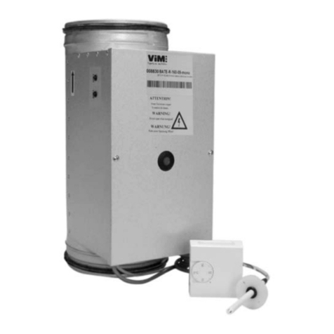
ViM BATE-R010 User manual

NT00000592-BATE-R-010-AN-191114
INSTRUCTION MANUAL
INSTALLATION | WIRING | COMMISSIONING | MAINTENANCE |
AFNOR CERTIFICATION
ISO 14001
Environnement
AFNOR CERTIFICATION
ISO 9001
Qualité
BATE-R010
Circular electrical heater with built-in control
for external 0-10V signal

2/8 NT00000592-BATE-R-010-AN-191114
CONTENTS
1. GENERAL INFORMATION ................................................................................................................ 2
1.1 Warnings .................................................................................................................................. 2
1.2 Safety instructions ................................................................................................................... 3
1.3 Reception - Storage.................................................................................................................. 3
1.4 Warranty .................................................................................................................................. 3
2. RANGE / PRODUCT PRESENTATION.............................................................................................. 3
3. INSTALLATION .................................................................................................................................. 4
3.1 Characteristics.......................................................................................................................... 4
3.2 Assembly.................................................................................................................................. 4
4. ELECTRICAL CONNECTION............................................................................................................ 5
4.1 BATE-R010 Single-phase - Power < 4kW................................................................................ 5
4.2 BATE-R010Single-phase-Power≥4kW ................................................................................ 6
4.3 BATE-R010 Three-phase - Power < 18kW............................................................................... 6
4.4 BATE-R010 Three-phase - Power ≥18kW............................................................................... 7
5. COMMISSIONING AND MAINTENANCE.......................................................................................... 7
5.1 Normal operation...................................................................................................................... 7
5.2 Fault resolution ........................................................................................................................ 8
5.3 Maintenance............................................................................................................................. 8
6. WASTE MANAGEMENT.................................................................................................................... 8
6.1 Treatment of packaging and General Industrial Waste (GIW).................................................. 8
6.2 Treatment of Professional WEEE............................................................................................. 8
1. GENERAL INFORMATION
1.1 Warnings
This product has been manufactured in compliance with strict technical safety rules in accordance with EC
standards,TheECdeclarationisdownloadablefromthewebsite(detailsonnalpage),
Before installing and using this product, read these instructions carefully as they contain important infor-
mation for your safety and user safety, during installation, operation and maintenance of this product, Once
installation is complete, ensure this manual is available for any later consultation,
The installation of this product and any other work (setup, connection, operation, maintenance) MUST be
carried out by a professional following applicable best industry practice, standards and safety rules, It must
comply with the requirements of the EMC and Low-Voltage Directives,
The manufacturer cannot be held liable for any injury and/or material damage caused by failure to comply
withthesafetyinstructionsorduetoanymodicationoftheproduct,
BATE electrical heater are intended to be inserted into rigid galvanised steel or aluminium circular pipe
systems for heating applications in tertiary buildings,
• Installation inside premises
• Speed in heater between 1,5m/s and 10m/s
• Environmental temperature between -20°C / +50°C
• Max, 95% relative humidity without condensation
• Non-potentially-explosive atmosphere
• Low-salinity atmosphere, without corrosive chemical agents

3/8 NT00000592-BATE-R-010-AN-191114
1.2 Safety instructions
Put on appropriate PPE (Personal Protective Equipment) before any work,
Ifworkhastobecarriedoutonthedevice,cutothepowersupplyonthemaincircuitbreakerandmake
sure that nobody can accidentally turn it back on,
Before operating the equipment, check the following points:
• Make sure that the device does not contain any foreign bodies,
• Check that all the components are mounted in their original positions,
• Check the earth connection,
• Check that the access hatch is properly closed,
1.3 Reception - Storage
In case of short shipment, non-conformity, and/or total or partial damage to the products delivered, the
Buyer must, in accordance with article 133-3 of the French Commercial Code, add written reservations to
thecarrier’sdeliveryslipandconrmthemwithin72hoursbyregisteredletterwithacknowledgementof
receipt with a duplicate for the seller, If the equipment is received without express reservation, the Buyer
has no subsequent recourse against us,
The product must be stored protected from weather, shocks and soiling due to splashing of any kind during
itstransportfromthesuppliertothenalcustomerandonthesitebeforeinstallation,
1.4 Warranty
The equipment is covered by a 12-month warranty - Only parts - from the date of invoice,
The seller undertakes to replace all parts or equipment that we recognise as malfunctioning, to the exclu-
sion of any damages or penalties such as operating losses, market injury or other non-material or indirect
damage,
The following are excluded from our warranty: faults connected with abnormal use or use not in accord-
ance with the recommendations in our manuals and instructions, defects found following normal wear and
tear, incidents caused by negligence, failure to monitor or maintain correctly, defects due to poor installa-
tion of the equipment or to poor storage conditions before installation,
Inanyevent,thesellerisnotresponsibleforequipmentthathasbeenmodiedorrepairedevenpartially,
2. RANGE / PRODUCT PRESENTATION
• Diameters from 125 to 500mm,
• Power from 600 to 18 000W
• Single-phase 230V 50Hz or three-phase 400V 50Hz power supply,
Standard construction
• Circular shell and Aluzinc treated steel IP44 connection box,
• Connection with class-C waterproof joints,
• IP44 cable grommet for cutting
• Sheathed 304 stainless steel heating elements,
• 1 automatic reset safety thermostat, set to 50°C,
• 1 manual reset safety thermostat, set to 100°C,
• 2 heating (red) / operating mode-fault (green) indicator LEDs
• 1 Triac-type electronic power regulator controlled by an external 0 - 10V signal,
• 1airvolumecut-outsensor,whichshutsotheheatingiftheairspeedisbelow1,5m/s,

4/8 NT00000592-BATE-R-010-AN-191114
3. INSTALLATION
3.1 Characteristics
A
B
C
DD
70Ø
Designation Power
(W) Current
(A) Weight
(kg) Dimensions (mm) Min. air
volume
(m3/h)
Max. air
volume
(m3/h)
A B C D
Single-phase 230V power supply
BATE R010 125 600W Single-phase
600 2,6 2,3 276 373 195 48,5 70 450
BATE R010 125 900W Single-phase
900 3,9 2,4 276 373 195 48,5 70 450
BATE R010 125 1 200W Single-phase
1 200 5,2 2,7 276 373 195 48,5 70 450
BATE R010 160 2 100W Single-phase
2 100 9,1 3,3 276 373 230 48,5 110 740
BATE R010 200 600W Single-phase
600 2,6 3,3 276 373 270 48,5 170 1 150
BATE R010 200 1 200W Single-phase
1 200 5,2 3,5 276 373 270 48,5 170 1150
BATE R010 200 3 000W Single-phase
3 000 13,0 3,9 276 373 270 48,5 170 1 150
BATE R010 250 1 200W Single-phase
1 200 5,2 4,5 276 373 320 48,5 270 1 800
BATE R010 250 3 000W Single-phase
3 000 13,0 7,0 276 373 320 48,5 270 1 800
BATE R010 315 900W Single-phase
900 3,9 7,5 276 376 385 50,0 420 2 850
BATE R010 315 1 500W Single-phase
1 500 6,5 7,6 276 376 385 50,0 420 2 850
BATE R010 315 3 000W Single-phase
3 000 13,0 10,5 276 376 385 50,0 420 2 850
BATE R010 400 3 000W Single-phase
3 000 13,0 9,1 276 376 470 50,0 680 4 600
BATE R010 400 5 000W Single-phase
5 000 21,7 10,2 276 376 470 50,0 680 4 600
400V Three-phase power supply
BATE R010 250 6 000W Three-phase
6 000 8,7 7,3 276 373 320 48,5 270 1 800
BATE R010 315 6 000W Three-phase
6 000 8,7 9,2 276 376 385 50,0 420 2 850
BATE R010 315 9 000W Three-phase
9 000 13,0 10,8 276 376 385 50,0 420 2 850
BATE R010 315 12 000W Three-phase
12 000 17,3 11,4 400 500 385 50,0 420 2 850
BATE R010 400 9 000W Three-phase
9 000 13,0 13,1 276 376 470 50,0 680 4 600
BATE R010 400 12 000W Three-phase
12 000 17,3 14,0 400 500 470 50,0 680 4 600
BATE R010 500 18 000W Three-phase
18 000 26,0 17,8 530 630 570 50,0 1 060 7 200
This data is visible on the identity plate on each product.
3.2 Assembly
Connection to aeraulic network
For rigid galvanised steel or A1 aluminium circular networks (M0).
Vertical or horizontal installation. Screw mounting.
Access to cover essential (manual reset). The electrical heater must be able to be disassembled for re-
placement and maintenance.
Possiblity to insulate externally the coil with A1 (M0) insulation. Do not isolate the cover.
Comply with the air direction indicated by the arrow.
DO NOT mount the connection box upside down. Any other position possible.

5/8 NT00000592-BATE-R-010-AN-191114
Respect a distance of 2 times the diameter between the heater and other network components. particularly
lters.
Respect a distance of 100mm between the heater and surrounding materials.
Airsupplydevices(vents/diusers)mustnotbeabletobetotallyblocked.
Electrical installation
Include a single-pole switch on the power supply with spacing of at least 3mm in a stationary system.
Make sure that the network fan turns on before or at the same time as the heater starts heating. Include a
post-ventilationdelaysothatthefanstopsaftertheheaterisshuto.(blockdiagram§"4.ELECTRICAL
CONNECTION".
The device is originally equipped with two safety thermostats to avoid overheating.
An automatic reset safety thermostat (50°C) and a manual reset safety thermostat (100°C) located on the
cover. They must control an external contactor (not supplied) that shuts o the mains power supply
in case of activation.
Attention : the control circuit is not galvanically isolated from the device’s power circuit.
Electrical wires and cables
• Max wire diameter for control connections: up to 4mm2.
• Max cable diameter for power supply:
10mm
2
16mm
2
Mono 230V ≤4,5kW ˃4,5kW
Tri 400V ≤15kW ˃15kW
4. ELECTRICAL CONNECTION
4.1 BATE-R010 Single-phase - Power < 4kW
1 phase power supply
airow
controller
according to NF C 15-100 standard
auto
reset
manual
reset
Command signal
L1
N
50°C
θ
100°C
θ
B
C
PTC
BATE-R010
PE
9
10
0...10Vcc
N
L
230V 50Hz
<4kW
Equipment
Included Optional
BATE R010 Electrical heater MCR1 Post-ventilation delay

6/8 NT00000592-BATE-R-010-AN-191114
4.2 BATE-R010 Single-phase - Power ≥ 4kW
airow
controller
auto
reset
manual
reset
Command signal
1 phase power supply
according to NF C 15-100 standard
Safety
thermostat
L1
N
50°C
θ
100°C
θ
B
C
PTC
BATE-R010
PE
9
6
5
10
0...10VDC
N
L
230V 50Hz
≥4kW
Equipment
Included Optional
BATE R010 Electrical heater MCR1 Post-ventilation delay
4.3 BATE-R010 Three-phase - Power < 18kW
3 phases power supply
airow
controller
auto
reset
manual
reset
Command signal
according to NF C 15-100 standard
Safety
thermostat
0...10VDC
50°C
θ
100°C
θ
B
C
PTC
BATE R010
PE
9
6
5
10
400V 50Hz
L1
L2
L3
L1
L2
L3
Equipment
Included Optional
BATE R010 Electrical heater MCR1 Post-ventilation delay

7/8 NT00000592-BATE-R-010-AN-191114
4.4 BATE-R010 Three-phase - Power ≥18kW
3 phases power supply
airow
controller
auto
reset
manual
reset
Command signal
according to NF C 15-100 standard
Safety
thermostat
0...10Vcc
400V 50Hz
L1
L2
50°C
θ
100°C
θ
B
C
PTC
BATE R010
PF
9
6
5
10
L3
N
L1
L2
L3
N
Inanycase,itmustnotbepossibletoshutothefanwithouttheheatershuttingobeforehand(MCR1-
type post-ventilation delay if necessary) or at the same time (to be avoided),
Post-ventilation block diagram
BDEZ
Safety thermostats
tted within the heater
MCR1
Fan ON/OFF
Power
supply
Coil supply
KM10
∆P
T1
A2 18
A1
N
Y1
L
15
230VAC 50Hz power supply
Main ON/OFF post-ventilation delay
airow controller
5. COMMISSIONING AND MAINTENANCE
5.1 Normal operation
Before start-up, the heater must be connected to the network and the cover must be closed,
The fan must be operational,

8/8 NT00000592-BATE-R-010-AN-191114
Cut o the power supply before opening the unit,
Do not touch live parts: Danger of death!
The printed circuit board is electrically charged when the heating device is live,
Indications of green “MODE” and red diodes :
The diode above is on when the heater is heating,
ThegreenMODEdiodeashesonceevery5seconds(for1minute),thenonceasecond,
5.2 Fault resolution
If the green MODE diode stays on, there is an air volume sensor fault,
Ifthereisnoairow,thegreenMODEdiodeashesonceevery5seconds,
Work must be carried out before operating the heater again,
Ifthereisnoairow,thegreenMODEdiodeashesonceevery5seconds,Whentheairowresumes,
the heater starts up again in normal mode,
If the manual reset safety thermostat is activated,
take the following measures:
Cutothepowersupply,
Carefully identify why the safety thermostat was ac-
tivated,
Once the error has been corrected, press the man-
ual safety thermostat “reset” button on the electrical
heater cover.
5.3 Maintenance
Regular inspection of connections,
Disassemble and clean the electrical heater as often as required by regulations and at least once a year,
6. WASTE MANAGEMENT
6.1 Treatment of packaging and General Industrial Waste (GIW)
Thepackaging(palletsnotondeposit,cartons,lms,woodenboxes)andotherGIWmustbemadereus-
able by an approved service provider,
It is strictly prohibited to burn, bury or dump them in the natural environment,
6.2 Treatment of Professional WEEE
Thisproductmustnotbedumpedortreatedwithhouseholdrefuse,butmustbedroppedoatanappro-
priate collection point for waste electrical and electronic equipment (WEEE),
Non-binding document. With a view to continuously improving equipment, the manufacturer reserves the
righttomakeanytechnicalmodicationswithoutgivingpriornotice.
VIM
Les prés de Mégy Sud – SOUDAN - CS 60120 - 79401 ST MAIXENT L’ECOLE CEDEX
Tel.: 05 49 06 60 38 or 05 49 06 60 25 – Fax: 05 49 06 60 36
Other manuals for BATE-R010
1
This manual suits for next models
7
Table of contents
Other ViM Heater manuals
Popular Heater manuals by other brands

L.B. White
L.B. White 320 Owner's manual and instructions

Dru
Dru SAXO Instructions for installation and operation

Royal Sovereign
Royal Sovereign HFN-20 Series owner's manual

Lasko
Lasko CT30710 Important instructions & operating manual

Sharper Image
Sharper Image 206938 user guide

Pacific energy
Pacific energy The Mirage A Series Installation and operating instructions