manuals.online logo
Brands
  1. Home
  2. •
  3. Brands
  4. •
  5. Vimar
  6. •
  7. Recording Equipment
  8. •
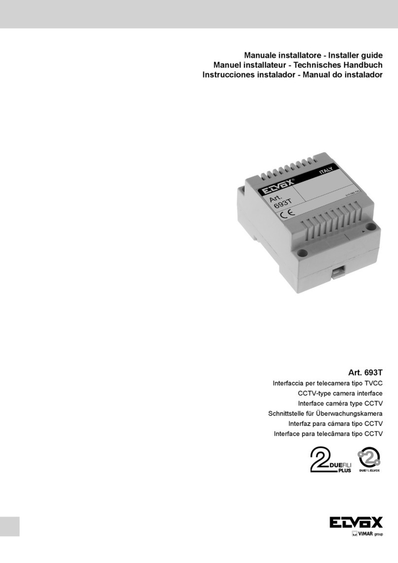
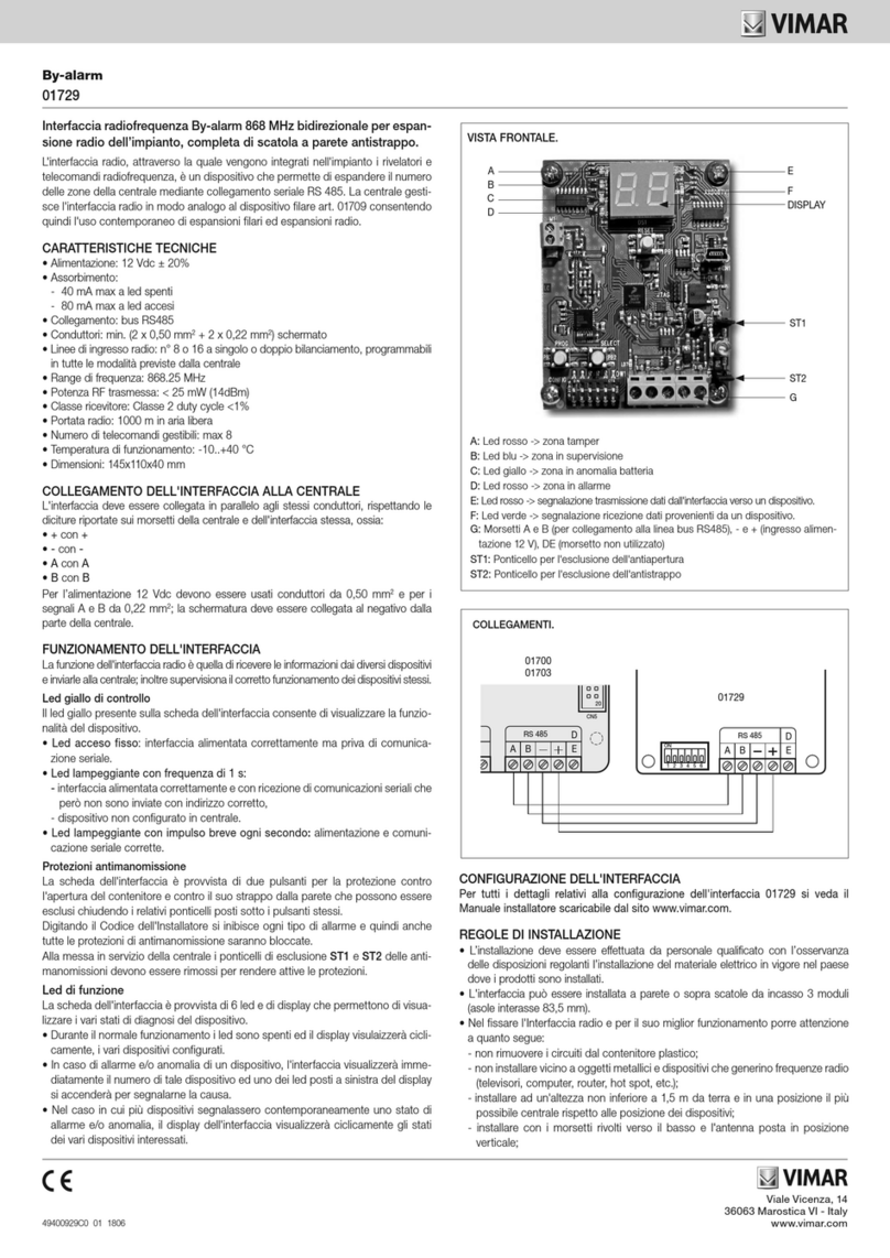
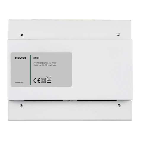
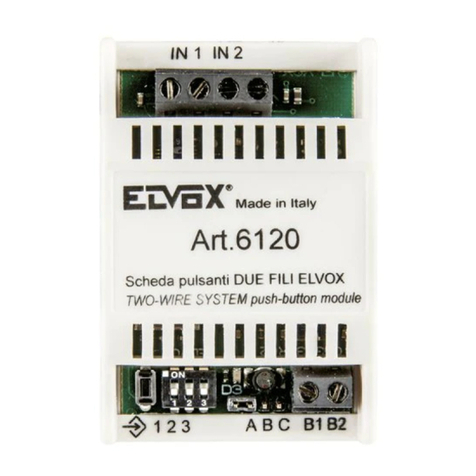
  9. Vimar ELVOX 6153 Assembly instructions

Vimar ELVOX 6153 Assembly instructions

Manuale installatore - Installer guide - Manuel installateur
Technisches Handbuch - Instrucciones instalador - Manual do instalador
6153
Modulo regolazione volume Digibus e Sound System
Digibus and Sound System volume adjustment module
Module réglementation volume Digibus et Sound System
Modul Lautstärkenregelung Digibus und Sound System
Módulo ajuste volumen Digibus y Sound System
Módulo ajuste volume Digibus e Sound System
DESCRIZIONE
Il modulo commutatore Art. 6153 per-
mette di regolare il volume di chiamata o
di escludere la stessa, nei citofoni con al-
toparlante di chiamata serie PETRARCA
Art. 6200 - 6201 - 6204. Il dispositivo è
munito anche di due dispositivi ottici,
uno per la visualizzazione dell’esclusione
della chiamata (segnalazione rossa) e
uno per lo stato di serratura aperta (se-
gnalazione verde); l’utilizzo di questi due
dispositivi richiede dei collegamenti sup-
plementari come indicato negli schemi di
collegamento.
* Nei citofoni Art. 6204, l’Art. 6153 è
adibito anche per la funzione “utente as-
sente” da utilizzare con i centralini digitali
DIGIBUS.
MONTAGGIO SU CITOFONI DELLA
SERIE PETRARCA 6200 - 6201 - 6204
- Aprire il citofono vedi (Fig. 1).
- Spezzare la lamella in plastica facendo
pressione sulla lamella (g. 2).
- Inserire la scheda nell’apposito allogia-
mento e ssarla con la vite in dotazione
(Fig. 3).
- Sconnettere il cavetto dell’altoparlante
dal piolino “A” del citofono.
- Inserire il cavetto appena tolto sul pio-
lino (CN2) presente sulla scheda Art.
6153.
- Inserire il cavetto, precollegato nel mor-
setto n° 6 dell’Art. 6153, sul piolino “A”
del citofono (Fig. 4).
N.B. Sul morsetto n° 7 della scheda Art.
6153 è presente un cavetto da utilizzarsi
per la segnalazione ottica di chiamata
esclusa.
Nei citofoni Art. 6204 utilizzare il cavetto
per collegare il morsetto 10 dell’art. 6153
al 6204 e il cablaggio per collegare il con-
nettore CN1 dell’art. 6153 al connettore
AU del citofono.
Selezione livello di chiamata
DESCRIPTION
Switching module type 6153 is used to
adjust the call volume or to switch off the
call function on PETRARCA series in-
terphones type 6200 - 6201 - 6204 with
call loudspeaker. The device is equipped
with two optical devices, one to display
the call exclusion (red indicator LED) and
the other for the open door lock status
(green indicator LED); the use of this two
devices requires additional wirings as
shown in the wiring diagrams.
* In interphones types 6204, type 6153 is
used also for the “unattended call func-
tion”; to be used with digital DIGIBUS
switchboards.
INSTALLATION ON PETRARCA SE-
RIES INTERPHONES TYPE 6200 - 6201
- 6204
- Open the interphone (see Fig. 1).
- Break the plastic lock by pressing on
the same lock (see Fig. 2).
- Insert the circuit board in proper seat
and x it with screws provided (see Fig.
3)
- Disconnect the loudspeaker cable from
the “A” interphone pin .
- Insert the just removed cable in pin
CN2, present on the circuit board type
6153.
- Insert the cable, pre-connected in n. 6
terminal of type 6153 circuit board, in
pin “A” of interphone (see Fig. 4).
N.B. On terminal n. 7 of type 6153 circuit
board there is cable to be used for the
call exclusion indicator LED.
On interphones type 6204 use the cable
to connect terminal 10 of type 6153 to
6204, and the harness to connect con-
nector CN1 of Art. 6153 to connector AU
of interphone.
Call level adjustment
Posizione “0”: esclusione suoneria
Posizione “1”: volume suoneria minimo
Posizione “2”: volume suoneria medio
Posizione “3”: volume suoneria massimo
N.B. In corrispondenza della posizione
“0” (suoneria esclusa) i morsetti 7 - 10
vengono cortocircuitati permettendo l’ac-
censione del segnalatore ottico rosso
(LED).
Position “0”: chime exclusion
Position “ 1 “: minimum chime volume
Position “ 2 “: medium chime volume
Position “3”: maximum chime volume
N.B. Terminals 7 - 10 are shorted in po-
sition 0 (call exclusion), enabling so the
connection of a red indicator LED.
DESCRIPTION
Le module commutateur Art. 6153 permet
de régler le volume d’appel ou d’exclure
le même appel dans les postes d’apparte-
ment avec haut-parleur d’appel série PE-
TRARCA Art. 6200 - 6201 - 6202 - 6204.
Le dispositif est muni aussi de deux dis-
positifs optiques, un pour la visualisation
de l’exclusion de l’appel (signalisation
rouge) et un qui signale “ gâche ouverte
“ (signalisation verte). L’emploi de ces
deux dispositifs demande des connec-
tions supplémentaires selon les schémas
de connection.
* Dans le postes d’appartement Art. 6204
l’Art. 6153 est utilisé même pour la fonc-
tion “usager absent”; à utiliser avec stan-
dards digitaux DIGIBUS.
MONTAGE SUR POSTES D’APPARTE-
MENT DE LA SÉRIE PETRARCA 6200
- 6201 - 6202 - 6204
- Ouvrir le poste d’appartement (voir fig.
1)
- Rompre la lamelle en plastique en fai-
sant pression sur la même lamelle (Fig.
2).
- Insérer la carte dans l’emplacement
approprié et la fixer avec la vis fournie
(Fig. 3).
- Débrancher le câble du haut-parleur
dès le picot “ A “ du poste d’apparte-
ment.
- Insérer le cable, juste enlévé, sur le
picot (CN2) présent sur la carte Art.
6153.
- Insérer le câble, preconnecté à la borne
n. 6 de l’art. 6153, sur le picot “ A “ du
poste d’appartement (Fig. 4).
N.B. Sur la borne n. 7 de la carte Art.
6153 il y a un câble à utiliser pour la si-
gnalisation optique d’appel exclu.
Dans les postes d’appartement Art. 6204
utiliser le câble pour raccorder la borne 10
de l’Art. 6153 à l’Art. 6204 et le câble de
liaison pour raccorder le connecteur CN1
de l’Art. 6153 au connecteur AU du poste
d’appartement.
Sélection du niveau d’appel
l’option “0”: exclusion de la sonnerie
l’option “1”: volume minimum de la son-
nerie
l’option “2”: volume moyen de la sonnerie
l’option “3”: volume maximum de la son-
nerie
N.B. En correspondance de la position “ 0
“ (sonnerie exclue) les bornes 7 - 10 sont
court-circuités en permettant l’allumage
du signalisateur optique rouge (LED).
0
0
1
1
2
23
Sinistra Destra
Left Right
0
0
1
1
2
23
Gauche Droite
0
0
1
1
2
23
2
6153
BESCHREIBUNG
Mit dem Umschaltmodul Art. 6153 kann
bei Sprechgeräten Serie PETRARCA
Art. 6200 - 6201 - 6202 - 6204 mit Ruf-
lautsprecher die Ruautstärke eingestellt
bzw. der Rufton deaktiviert werden.
An die Vorrichtung des Umschaltmoduls
lassen sich zwei optische Anzeigen (eine
für die Ruftonabschaltungsanzeige (rote
LED) und die andere für den geöffneten
Türöffnerstatus (grüne LED) anschlies-
sen: deren Anwendung fordert Zusatzan-
schlüsse wie in Schaltplan gezeigt.
* Bei Haustelefonen Art. 6204 und 6153
ist die Taste für die “Abwesender Benut-
zer”-Funktion verwendet; um mit digitalen
DIGIBUS Zentralen zu nutzen.
EINBAU AUF SPRECHGERÄTE BAU-
REIHE PETRARCA 6200 - 6201 - 6202
- 6204
- Das Haustelefon öffnen (siehe Abb. 1).
- Die Kunststottabdeckung ausbrechen
(siehe Abb. 2)
- Die Karte in den passenden Sitz einset-
zen und sie mittels der mitgelieferten
Schraube befestigen (siehe Abb.3).
- Das Lautsprecherkabel vom Stecker-
stift “A” des Haustelefon abnehmen.
- Das eben abgenommene Kabel auf den
bei der Karte Art. 6153 anwesenden
Steckerstift (CN2), einstecken.
Das Kabel, das an Klemme n. 6 des
Arts. 6153 angeschlossen war, an Ste-
ckerstift “A” des Haustelefons anste-
cken (siehe Abb. 4).
HINWEIS: Bei Klemme n. 7 der Karte
6153 gibt es ein Kabel, das für die op-
tische Rufabschaltungsanzeige zu ver-
wenden ist.
Bei Haustelefonen Art. 6204 das Kabel
für den Anschluß der Klemme 10 des Art.
6153 an Art. 6204 verwenden und das
Verbindungskabel für den Anschluß des
Verbinders CN1 des Art. 6153 an Verbin-
der AU des Haustelefons verwenden.
Einstellung der Lautstärke des Läutwerks
Stellung “0”: Läutwerk ausgeschaltet
Stellung “1”: Lautstärke des Läutwerks
niedrig
Stellung “2”: Lautstärke des Läutwerks
mittel
Stellung “3”: Lautstärke des Läuwerks
hoch
HINWEIS: In Stellung “0” (Läutwerk aus-
geschaltet) sind die Klemmen 7 - 10 kurz-
geschlossen und ermöglichen damit den
Anschluß einer roten optischen Anzeige
(LED).
Links Rechts
0
0
1
1
2
23
DESCRIÇÃO
O módulo comutador Art. 6153 permite
a regulação do volume de chamada ou
de excluir a mesma chamada nos in-
terfones com altifalante de chamada da
série PETRARCA Art. 6200 - 6201 - 6202
- 6204. O dispositivo está ainda equipado
de dois dispositivos ópticos, um para a
visualização da exclusão de chamada
(sinalização vermelha) e um para o es-
tado de trinco aberto (sinalização verde);
o uso destos dois dispositivos pretendem
algumas ligações suplementares como
indicam os esquemas de ligação.
* Nos interfones Art. 6204, o Art. 6153
é utilizado mesmo para a função “utente
ausente”; para utilizar nas centrais digi-
tais DIGIBUS.
MONTAGEM NOS INTERFONES DA
SERIE PETRARCA 6200 - 6201 - 6202
- 6204
- Abrir o interfone (ver Fig. 1).
- Romper a lamela em plástico fazendo
pressão sobre a mesma (ver Fig. 2).
- Inserir a placa no lugar apropriado e
xarla com o parafuso fornecido (ver
g. 3).
- Desligar o cabo do altifalante do pino
“A” do interfone.
- Inserir o cabo apenas desligado no
pino (CN2) presente na placa Art.
6153.
- Inserir o cabo, anteriormente ligado no
borne n. 6 do Art. 6153, no pino “A” do
interfono (ver Fig. 4).
N.B. No terminal n. 7 da placa Art. 6153
há un cabo para utilizar para a sinaliza-
ção óptica da chamada excluida.
Nos interfones Art. 6204 utilizar o cabo
para ligar o borne 10 do Art. 6153 ao Art.
6204 e a cablagem para ligar o conetor
CN1 do Art. 6153 ao conetor AU do in-
terfone.
Seleccão nivel de chamada
DESCRIPCIÓN
El módulo conmutador Art. 6153 permite
regular el volumen de llamada o excluir
la misma llamda en los interfonos con al-
tavoz de llamada serie PETRARCA Art.
6200 - 6201 - 6202 - 6204. El dispositivo
está provisto también de dos dispositivos
ópticos, uno para la visualización de la
exclusión de la llamada (señalación roja)
y uno que indica “cerradura abierta” (se-
ñalación verde); la utilización de estos
dos dispositivos requiere conexionados
suplementarios como indican los esque-
mas de conexionado.
* En los interfonos Art. 6204, el Art. 6153
sirve también para la función “usuario
ausente”; para utilizar con las centrales
digitales DIGIBUS:
MONTAJE SOBRE INTERFONOS DE
LA SERIE PETRARCA 6200 - 6201 -
6202 - 6204
- Abrir el interfono (ver Fig. 1)
- Romper la laminilla en plástico ha-
ciendo presión sobre la laminilla (Fig.
3).
- Insertar la ficha en el alojamiento apro-
piado y fijarla con el tornillo en dotación
(Fig. 3).
- Desconectar el cable del altavoz desde
el borne “A” del interfono.
- Insertar el cable recién quitado en el
borne (CN2) presente en la ficha Art.
6153.
- Insertar el cable, preconectado en el
borne n. 6 del Art. 6153, en el borne
“A” del interfono (Fig. 4).
N.B. En el borne n. 7 de la cha Art. 6153
hay un cable que se utiliza para la seña-
lación óptica de “exclusión de llamada”.
En los interfonos Art. 6204 utilizar el
cable para conectar el borne 10 del Art.
6153 al 6204 y el cableado para conectar
el conector CN1 del Art. 6153 al conector
AU del interfono.
Selección nivel de llamada
Posición “0”: exclusión timbre
Posición “1”: volumen mínimo timbre
Posición “2”: columen medio timbre
Posición “3”: volumen máximo timbre.
N.B. En correspondencia de la posición
“0” (exclusión del timbre) los bornes 7 -
10 vienen cortocircuitados permitiendo el
encendido del LED rojo.
Posição “ 0 “: exclusão da campainha
Posição “ 1 “ : volume mínimo campainha
Posição “ 2 “: volume medio campainha
Posição “ 3 “: volume máximo campainha
N.B. Em correspondencia com a posição
“0” (campainha excluida) os terminais 7
- 10 são curto-circuitados tornando pos-
sível o acendimento do led sinalizador
vermelho (Art. 6153).
izquierda derecha
0
0
1
1
2
23 ezquerda direita
0
0
1
1
2
23
3
6153
A
C
R0
BL
BI
Fig. 1
Fig. 3
Fig. 4
Fig. 2
4
6153
6
2
A
CN2
DL2
DL1
1
10
8
9
7
3S CH+U
C
A
1
6
6S
6P
5
6E
3
2
7
AU
A-+U+I
PRI
BCD
CH
CH
3
S
1
2
1
9
DL2
123
10
3
CN2
6S
6
DL1 7
8
6E
C
A
6
6P
5
AU
2
1
7
CHS
CH
S
CH
3
2
Agli alimentatori
To power supplies
Vers les alimentations
Zu den Netzgeräten
A los alimentadores
Para os alimentadores
Art. 931-936-938A
Rete-Mains-Réseau
Netz-Red-Rede
Alimentatore
Power supply
Alimentation
Netzgerät
Alimentador
Art. 6582
SCHEMA DI COLLEGAMENTO ART. 6153 CON CITOFONO ART. 6200 E
SEGNALAZIONE OTTICA DI CHIAMATA ESCLUSA.
WIRING DIAGRAM FOR TYPE 6153 WITH INTERPHONE TYPE 6200 AND CALL
EXCLUSION INDICATOR LED
SCHÉMA DE RACCORDEMENT ART. 6153 AVEC POSTE D’APPARTEMENT 6200
ET SIGNALISATION OPTIQUE DE L’EXCLUSION DE L’APPEL.
Citofono - Phone
Poste - Haustelefon
Interfono - Telefone
Art. 6200
Agli alimentatori
To power supplies
Vers les alimentations
Zu den Netzgeräten
A los alimentadores
Para os alimentadores
Art. 931-936-938A
SCHEMA DI COLLEGAMENTO ART. 6153 CON
CITOFONO ART. 6200
WIRING DIAGRAM FOR ART. 6153 WITH
INTERPHONE SERIES 6200
SCHÉMA DE RACCORDEMENT ART. 6153 AVEC
POSTE D’APPARTEMENT ART. 6200.
ANSCHLUSSPLAN FÜR ART. 6153 MIT
HAUSTELEFONE SERIE 6200
ESQUEMA DE CONEXIONADO ART. 6153 CON
INTERFONO ART. 6200.
ESQUEMA DE LIGAÇÃO DO ART. 6153 COM
INTERFONE ART. 6200
DL2 - Segnalazione ottica rossa (LED).
DL2 - Red indicator led (LED)
DL2 - Signalisation optique rouge (LED)
DL2 - Rote LED Anzeige (LED)
DL2 - Señalation óptica roja (LED)
DL2 - LED indicador vermelho (LED)
Citofono - Phone
Poste - Haustelefon
Interfono - Telefone
Art. 6200
ANSCHLUSSPLAN FÜR ART. 6153 MIT
HAUSTELEFON ART. 6200 UND ANZEIGE DER
RUFABSCHALTUNG
ESQUEMA DE CONEXIONADO ART. 6153 CON
INTERFONO ART. 6200 Y SEÑALACIÓN ÓPTICA DE
EXCLUSIÓN DE LLAMADA.
ESQUEMA DE LIGAÇÃO DO ART. 6153 COM
INTERFONE ART. 6200 E MÓDULO DE SINALIZÇÃO DE
EXCLUSÃO DA CHAMADA.
A
A- Art. 6153
A- Art. 6153
5
6153
6
2
A
CN2
DL2
DL1
1
10
8
9
7
3SCCH+U
C
A
1
6
6S
6P
5
6E
3
2
7
AU
S/S1
15/AS
A-+U+I
PRI
BCD
CH
CH
3
S
1
2
SCHEMA DI COLLEGAMENTO ART. 6153 CON CITOFONO ART. 6200, SEGNALAZIONE OTTICA DI CHIAMATA ESCLUSA
E DI SERRATURA APERTA.
WIRING DIAGRAM FOR TYPE 6153 WITH INTERPHONE TYPE 6200, CALL EXCLUSION AND OPEN DOOR LOCK
INDICATOR LEDS
SCHÉMA DE RACCORDEMENT ART. 6153 AVEC POSTE D’APPARTEMENT ART. 6200, SIGNALISATION OPTIQUE DE
L’EXCLUSION DE L’APPEL ET GÂCHE OUVERTE.
ANSCHLUSSPLAN FÜR ART. 6153 MIT HAUSTELEFON ART. 6200 UND ANZEIGEN FÜR DIE RUFABSCHALTUNG UND
TÜRSCHLOSS GEÖFFNET
ESQUEMA DE CONEXIONADO ART. 6153 CON INTERFONO ART. 6200, SEÑALACIÓN ÓPTICA DE EXCLUSIÓN
LLAMADA Y DE CERRADURA ABIERTA.
ESQUEMA DE LIGAÇÃO DO ART. 6153 COM INTERFONE ART. 6200, E MÓDULOS DE SINALIZÇÃO DE EXCLUSÃO DE
CHAMADA E DE TRINCO ABERTO.
Citofono - Phone
Poste - Haustelefon
Interfono - Telefone
Art. 6200
Rete-Mains
Réseau-Netz
Red-Rede
Alimentatore
Power supply
Alimentation
Netzgerät
Alimentador
Art. 6582
Agli alimentatori
To power supplies
Vers les alimentations
Zu den Netzgeräten
A los alimentadores
Para os alimentadores
Art. 931-936-938A
DL2 - Segnalazione ottica rossa (LED).
DL2 - Red indicator led (LED)
DL2 - Signalisation optique rouge (LED)
DL2 - Rote LED Anzeige (LED)
DL2 - Señalation óptica roja (LED)
DL2 - LED indicador vermelho (LED)
DL1 - Segnalazione ottica verde (LED)
DL1 - Green indicator led (LED)
DL1 - Signalisation optique verte (LED)
DL1 - Grüne LED Anzeige (LED)
DL1 - Señalación óptica verde (LED)
DL1 - LED indicador verde (LED)
A- Art. 6153
6
6153
DL2 9
10
V12+-S3
DL1CN2
A
C
3
6S
6
8
7
6E
6
6P
5
CN1
AU
1
2
7
CN2
CH
CN1
M
+A
-
+D
CH
+
M
V3
V2
V1
+
CH
CH
1
3
S
-
2
V
A
Citofono - Phone
Poste - Haustelefon
Interfono - Telefone
Art. 6200
SCHEMA DI COLLEGAMENTO ART. 6153 CON CITOFONO ART. 6200 E MONITOR.
WIRING DIAGRAM FOR ART. 6153 WITH INTERPHONE TYPE 6200 AND MONITOR
SCHÉMA DE RACCORDEMENT ART. 6153 AVEC POSTE D’APPARTEMENT ART. 6200 ET MONITEUR.
ANSCHLUSSPLAN FÜR ART. 6153 MIT HAUSTELEFON ART. 6200 UND MONITOR
ESQUEMA DE CONEXIONADO ART. 6153 CON INTERFONO ART. 6200 Y MONITOR.
ESQUEMA DE LIGAÇÃO DO ART. 6153 COM INTERFONE ART. 6200 E MONITOR.
All’ alimentatore
To power supply
Vers l’alimentation
Zu dem Netzgerät
Al alimentador
Para o alimentador
Art. 6680
Monitor
Moniteur
Art. 6020
Art. 6023
A- Art. 6153
7
6153
C+U-A+I BD
PRI
7
CN2 DL1
DL2
A
8
10
9
5
A
C
6P
6
6S
6
6E
AU
2
1
3
7
CN1
+1V32S-CH
+
CN1
CH
CN2
+D
-
M
V3
+A
V1
V2
M
S
CH
-
CH
+
2
3
1
V
+U
Citofono - Phone
Poste - Haustelefon
Interfono - Telefone
Art. 6200
All’ alimentatore
To power supply
Vers l’alimentation
Zu dem Netzgerät
Al alimentador
Para o alimentador
Art. 6680
Monitor
Moniteur
Art. 6020
Art. 6023
Rete-Mains
Réseau-Netz
Red-Rede
Alimentatore
Power supply
Alimentation
Netzgerät
Alimentador
Art. 6582
DL2 - Segnalazione ottica rossa (LED).
DL2 - Red indicator led (LED)
DL2 - Signalisation optique rouge (LED)
DL2 - Rote LED Anzeige (LED)
DL2 - Señalation óptica roja (LED)
DL2 - LED indicador vermelho (LED)
A- Art. 6153
SCHEMA DI COLLEGAMENTO ART. 6153 CON CITOFONO ART. 6200, MONITOR E SEGNALAZIONE OTTICA DI
CHIAMATA ESCLUSA.
WIRING DIAGRAM FOR TYPE 6153 WITH INTERPHONE TYPE 6200, MONITOR AND CALL EXCLUSION INDICATOR LED.
SCHÉMA DE RACCORDEMENT ART. 6153 AVEC POSTE D’APPARTEMENT ART. 6200, MONITEUR ET SIGNALISATION
OPTIQUE DE L’EXCLUSION DE L’APPEL.
ANSCHLUSSPLAN FÜR ART. 6153 MIT HAUSTELEFON ART. 6200, MONITOR UND ANZEIGE DER RUFABSCHALTUNG.
ESQUEMA DE CONEXIONADO ART. 6153 CON INTERFONO ART. 6200, MONITOR Y SEÑALACIÓN ÓPTICA DE
EXCLUSIÓN DE LLAMADA.
ESQUEMA DE LIGAÇÃO DO ART. 6153 COM INTERFONE ART. 6200, MONITOR E MÓDULO DE SINALIZÇÃO DE
EXCLUSÃO DE CHAMADA.
8
6153
+D
6C
A
9
10
A
CN2
6
DL1
DL2
7
8
6P
6S
1V32S
2
5
6E
3
7
1
AU
CN1
CH
CN2
+U-+ CH
M
CN1
-
+
+A
V3
M
V2
V1
+I-+UBA
PRI
DC
+
CH
CH
3
S
-
V
2
1
C
15/AS
S/S1
Citofono - Phone
Poste - Haustelefon
Interfono - Telefone
Art. 6200
SCHEMA DI COLLEGAMENTO ART. 6153 CON CITOFONO ART. 6200, MONITOR, SEGNALAZIONE OTTICA DI CHIAMATA
ESCLUSA E DI SERRATURA APERTA.
WIRING DIAGRAM FOR TYPE 6153 WITH INTERPHONE TYPE 6200, MONITOR, CALL EXCLUSION AND OPEN DOOR
LOCK INDICATOR LEDS.
SCHÉMA DE RACCORDEMENT ART. 6153 AVEC POSTE D’APPARTEMENT ART. 6200, MONITEUR, SIGNALISATION
OPTIQUE DE L’EXCLUSION DE L’APPEL ET GÂCHE OUVERTE.
ANSCHLUSSPLAN FÜR ART. 6153 MIT HAUSTELEFON ART. 6200, MONITOR UND ANZEIGEN FÜR DIE
RUFABSCHALTUNG UND TÜRSCHLOSS GEÖFFNET.
ESQUEMA DE CONEXIONADO ART. 6153 CON INTERFONO ART. 6200, MONITOR, SEÑALACIÓN ÓPTICA DE
EXCLUSIÓN DE LLAMADA Y DE CERRADURA ABIERTA.
ESQUEMA DE LIGAÇÃO DO ART. 6153 COM INTERFONE ART. 6200, MONITOR E MÓDULOS DE SINALIZÇÃO DE
EXCLUSÃO DE CHAMADA E TRINCO ABERTO.
All’ alimentatore
To power supply
Vers l’alimentation
Zu dem Netzgerät
Al alimentador
Para o alimentador
Art. 6680
Monitor
Moniteur
Art. 6020
Art. 6023
Rete-Mains
Réseau-Netz
Red-Rede
Alimentatore
Power supply
Alimentation
Netzgerät
Alimentador
Art. 6582
DL1 - Segnalazione ottica verde (LED)
DL1 - Green indicator led (LED)
DL1 - Signalisation optique verte (LED)
DL1 - Grüne LED Anzeige (LED)
DL1 - Señalación óptica verde (LED)
DL1 - LED indicador verde (LED)
DL2 - Segnalazione ottica rossa (LED).
DL2 - Red indicator led (LED)
DL2 - Signalisation optique rouge (LED)
DL2 - Rote LED Anzeige (LED)
DL2 - Señalation óptica roja (LED)
DL2 - LED indicador vermelho (LED)
A- Art. 6153
9
6153
DL1
DL2
A
CN2
SR
C
SD
CN3
8
3+U
10
9
CH
CH
CH
3
7
6
6
5
4
1
2
3
+U-A+I DCB
PRI
8
10
DL2 9
CH3
3
CN2
A
DL1 7
6
6
SR
C
SD
5
4
1
2
CH
3
CH
CN4
Agli alimentatori
To power supplies
Vers les alimentations
Zu den Netzgeräten
A los alimentadores
Para os alimentadores
Art. 6837
Citofono - Phone
Poste - Haustelefon
Interfono - Telefone
Art. 6201
SCHEMA DI COLLEGAMENTO ART. 6153 CON CITOFONO
ART. 6201
WIRING DIAGRAM FOR ART. 6153 WITH INTERPHONE
TYPE 6201
SCHÉMA DE RACCORDEMENT ART. 6153 AVEC POSTE
D’APPARTEMENT ART. 6201.
ANSCHLUSSPLAN FÜR ART. 6153 MIT HAUSTELEFON
ART. 6201
ESQUEMA DE CONEXIONADO ART. 6153 CON
INTERFONO ART. 6201.
ESQUEMA DE LIGAÇÃO DO ART. 6153 COM INTERFONE
ART. 6201.
SCHEMA DI COLLEGAMENTO ART. 6153 CON
CITOFONO ART. 6201 E SEGNALAZIONE OTTICA DI
CHIAMATA ESCLUSA.
WIRING DIAGRAM FOR TYPE 6153 WITH INTERPHONE
TYPE 6201 AND CALL EXCLUSION INDICATOR LED.
SCHÉMA DE RACCORDEMENT ART. 6153 AVEC POSTE
D’APPARTEMENT 6201 ET SIGNALISATION OPTIQUE DE
L’EXCLUSION DE L’APPEL.
ANSCHLUSSPLAN FÜR ART. 6153 MIT HAUSTELEFON
ART. 6201 UND ANZEIGE DER RUFABSCHALTUNG.
ESQUEMA DE CONEXIONADO ART. 6153 CON
INTERFONO ART. 6201 Y SEÑALACIÓN ÓPTICA DE
EXCLUSIÓN DE LLAMADA.
ESQUEMA DE LIGAÇÃO DO ART. 6153 COM INTERFONE
ART. 6201 E MÓDULO DE SINALIZÇÃO DE EXCLUSÃO
DE CHAMADA.
Citofono - Phone
Poste - Haustelefon
Interfono - Telefone
Art. 6201
Rete-Mains
Réseau-Netz
Red-Rede
Alimentatore
Power supply
Alimentation
Netzgerät
Alimentador
Art. 6582
Agli alimentatori
To power supplies
Vers les alimentations
Zu den Netzgeräten
A los alimentadores
Para os alimentadores
Art. 6837
DL2 - Segnalazione ottica rossa (LED).
DL2 - Red indicator led (LED)
DL2 - Signalisation optique rouge (LED)
DL2 - Rote LED Anzeige (LED)
DL2 - Señalation óptica roja (LED)
DL2 - LED indicador vermelho (LED)
A- Art. 6153
A- Art. 6153
A
A
10
6153
+
I
O
1
5
PRI
A
B
C
+
U
-
C
6
DL1
A
C
N
2
9
1
0
7
8
SD
SR
C
A
C
N
3
4
5
6
1
2
3
CH
+
U
3
CH
CH
3
1
5/
A
S
S/S1
C
SCHEMA DI COLLEGAMENTO ART. 6153 CON CITOFONO ART. 6201, SEGNALAZIONE OTTICA DI CHIAMATA ESCLUSA
E DI SERRATURA APERTA.
WIRING DIAGRAM FOR TYPE 6153 WITH INTERPHONE TYPE 6201, CALL EXCLUSION AND OPEN DOOR INDICATOR
LEDS.
SCHÉMA DE RACCORDEMENT ART. 6153 AVEC POSTE D’APPARTEMENT ART. 6201, SIGNALISATION OPTIQUE DE
L’EXCLUSION DE L’APPEL ET GÂCHE OUVERTE.
ANSCHLUSSPLAN FÜR ART. 6153 MIT HAUSTELEFON ART. 6201 UND ANZEIGEN FÜR DIE RUFABSCHALTUNG UND
TÜRSCHLOSS GEÖFFNET.
ESQUEMA DE CONEXIONADO ART. 6153 CON INTERFONO ART. 6201, SEÑALACIÓN ÓPTICA DE EXCLUSIÓN LLAMADA
Y DE CERRADURA ABIERTA.
ESQUEMA DE LIGAÇÃO DO ART. 6153 COM INTERFONE ART. 6201 E MÓDULOS DE SINALIZÇÃO DE EXCLUSÃO DE
CHAMADA E TRINCO ABERTO,
Citofono - Phone
Poste - Haustelefon
Interfono - Telefone
Art. 6201
Rete-Mains
Réseau-Netz
Red-Rede
Alimentatore
Power supply
Alimentation
Netzgerät
Alimentador
Art. 6583
Agli alimentatori
To power supplies
Vers les alimentations
Zu den Netzgeräten
A los alimentadores
Para os alimentadores
Art. 6837
DL2 - Segnalazione ottica rossa (LED).
DL2 - Red indicator led (LED)
DL2 - Signalisation optique rouge (LED)
DL2 - Rote LED Anzeige (LED)
DL2 - Señalation óptica roja (LED)
DL2 - LED indicador vermelho (LED)
DL1 - Segnalazione ottica verde (LED)
DL1 - Green indicator led (LED)
DL1 - Signalisation optique verte (LED)
DL1 - Grüne LED Anzeige (LED)
DL1 - Señalación óptica verde (LED)
DL1 - LED indicador verde (LED)
A- Art. 6153
11
6153
V1 V2 CH+-
C
7
10
DL2 9
8
CN2
A
DL1
6
3
SR
SD
5
6
4
CN3
1
2
CN4
V3
+D
CN2
CH
CN1
+A
+
-
M
V2
M
V1
-
CH
CH
V1
V2
+
V1 V2 CH+U+-
C
7
10
DL2 9
8
CN2
A
DL1
6
3
SR
SD
5
6
4
CN3
1
2
CN4
V3
+D
CN2
CH
CN1
+A
+
-
M
V2
M
V1
-
CH
CH
V1
V2
+
-+I+U
PRI
BCAD
Citofono - Phone
Poste - Haustelefon
Interfono - Telefone
Art. 6201
SCHEMA DI COLLEGAMENTO ART. 6153 CON CITOFONO
ART. 6201 E MONITOR.
WIRING DIAGRAM FOR TYPE 6153 WITH INTERPHONE
TYPE 6201 AND MONITOR.
SCHÉMA DE RACCORDEMENT ART. 6153 AVEC POSTE
D’APPARTEMENT ART. 6201 ET MONITEUR.
ANSCHLUSSPLAN FÜR ART. 6153 MIT HAUSTELEFON
ART. 6201 UND MONITOR.
ESQUEMA DE CONEXIONADO ART. 6153 CON
INTERFONO ART. 6201 Y MONITOR.
ESQUEMA DE LIGAÇÃO DO ART. 6153 COM INTERFONE
ART. 6201 E MONITOR.
All’ alimentatore
To power supply
Vers l’alimentation
Zu dem Netzgerät
Al alimentador
Para o alimentador
Art. 6568
Monitor
Moniteur
Art. 6020
Citofono - Phone
Poste - Haustelefon
Interfono - Telefone
Art. 6201
SCHEMA DI COLLEGAMENTO ART. 6153 CON
CITOFONO ART. 6201, MONITOR E SEGNALAZIONE
OTTICA DI CHIAMATA ESCLUSA.
WIRING DIAGRAM FOR TYPE 6153 WITH INTERPHONES
SERIES 6201, MONITOR AND CALL EXCLUSION
INDICATOR LED.
SCHÉMA DE RACCORDEMENT ART. 6153 AVEC
POSTE D’APPARTEMENT ART. 6201, MONITEUR
ET SIGNALISATION OPTIQUE DE L’EXCLUSION DE
L’APPEL.
ANSCHLUSSPLAN FÜR ART. 6153 MIT HAUSTELEFON
ART. 6201, MONITOR UND ANZEIGE DER
RUFABSCHALTUNG.
ESQUEMA DE CONEXIONADO ART. 6153 CON
INTERFONO ART. 6201, MONITOR Y SEÑALACIÓN
ÓPTICA DE EXCLUSIÓN DE LLAMADA.
ESQUEMA DE LIGAÇÃO DO ART. 6153 COM INTERFONE
ART. 6201, MONITOR E MÓDULO DE SINALIZÇÃO DE
EXCLUSÃO DE CHAMADA.
All’ alimentatore
To power supply
Vers l’alimentation
Zu dem Netzgerät
Al alimentador
Para o alimentador
Art. 6568
Monitor
Moniteur
Art. 6020
Rete-Mains
Réseau-Netz
Red-Rede
Alimentatore
Power supply
Alimentation
Netzgerät
Alimentador
Art. 6582
DL2 - Segnalazione
ottica rossa
(LED).
DL2 - Red indicator led
(LED)
DL2 - Signalisation
optique rouge
(LED)
DL2 - Rote LED Anzeige
(LED)
DL2 - Señalation óptica
roja (LED)
DL2 - LED indicador
vermelho (LED)
A
A- Art. 6153
A
A- Art. 6153
12
6153
DL2 9
10
V1 -S23 +C+U CH
3
CN2
A
C
6S
6
8
7
DL1
6E
6
6P
5
CN1
AU
1
2
7
CN2
M
CN1
+A
-
+D
CH
+
M
V3
V2
V1
15/AS
S/S1
-+U+IA BCD
+
CH
CH
1
3
-
S
2
V
PRI
Citofono - Phone
Poste - Haustelefon
Interfono - Telefone
Art. 6201
SCHEMA DI COLLEGAMENTO ART. 6153 CON CITOFONO ART. 6201, MONITOR, SEGNALAZIONE OTTICA DI CHIAMATA
ESCLUSA E DI SERRATURA APERTA.
WIRING DIAGRAM FOR TYPE 6153 WITH INTERPHONE TYPE 6201, MONITOR, RUF EXCLUSION AND OPEN DOOR
INDICATOR LEDS.
SCHÉMA DE RACCORDEMENT ART. 6153 AVEC POSTE D’APPARTEMENT ART. 6201, MONITEUR, SIGNALISATION
OPTIQUE DE L’EXCLUSION DE L’APPEL ET GÂCHE OUVERTE.
ANSCHLUSSPLAN FÜR ART. 6153 MIT HAUSTELEFON ART. 6201, MONITOR UND ANZEIGEN FÜR DIE
RUFABSCHALTUNG UND TÜRSCHLOSS GEÖFFNET.
ESQUEMA DE CONEXIONADO ART. 6153 CON INTERFONO ART. 6200, MONITOR, SEÑALACIÓN ÓPTICA DE EXCLUSIÓN
DE LLAMADA Y DE CERRADURA ABIERTA.
ESQUEMA DE LIGAÇÃO DO ART. 6153 COM INTERFONE ART. 6201, MONITOR E MÓDULOS DE SINALIZÇÃO DE
EXCLUSÃO DE CHAMADA E TRINCO ABERTO.
All’ alimentatore
To power supply
Vers l’alimentation
Zu dem Netzgerät
Al alimentador
Para o alimentador
Art. 6568
Monitor
Moniteur
Art. 6020
Rete-Mains
Réseau-Netz
Red-Rede Alimentatore
Power supply
Alimentation
Netzgerät
Alimentador
Art. 6582
DL1 - Segnalazione ottica verde (LED)
DL1 - Green indicator led (LED)
DL1 - Signalisation optique verte (LED)
DL1 - Grüne LED Anzeige (LED)
DL1 - Señalación óptica verde (LED)
DL1 - LED indicador verde (LED)
DL2 - Segnalazione ottica rossa (LED).
DL2 - Red indicator led (LED)
DL2 - Signalisation optique rouge (LED)
DL2 - Rote LED Anzeige (LED)
DL2 - Señalation óptica roja (LED)
DL2 - LED indicador vermelho (LED)
A- Art. 6153
A
13
6153
5
8
DL2
10
9
A-
CN2
6
DL1
7
BL
BL
A+
C11
12
6
1
3
4
1+U 354
S/S1
15/AS
+U-+IBADC
3
5
4
1
PRI
C
CN1
AU
Agli alimentatori
To power supplies
Vers les alimentations
Zu den Netzgeräten
A los alimentadores
Para os alimentadores
Art. 6941 - 6948
Citofono - Phone
Poste - Haustelefon
Interfono - Telefone
Art. 6204
SCHEMA DI COLLEGAMENTO ART. 6153 CON CITOFONO ART. 6204, MONITOR, SEGNALAZIONE OTTICA DI CHIAMATA
ESCLUSA, DI SERRATURA APERTA E FUNZIONE UTENTE ASSENTE.
WIRING DIAGRAM FOR TYPE 6153 WITH INTERPHONE TYPE 6201, MONITOR, CALL EXCLUSION, OPEN DOOR INDICATOR
LEDS AND ABSENT USER FUNCTION.
SCHÉMA DE RACCORDEMENT ART. 6153 AVEC POSTE D’APPARTEMENT ART. 6201, MONITEUR, SIGNALISATION OPTIQUE
DE L’EXCLUSION DE L’APPEL, GÂCHE OUVERTE ET FONCTION USAGER ABSENT.
ANSCHLUSSPLAN FÜR ART. 6153 MIT HAUSTELEFON ART. 6201, MONITOR UND ANZEIGEN FÜR DIE RUFABSCHALTUNG,
TÜRSCHLOSS GEÖFFNET UND UNANWESENDEN BENUTZER FUNKTION.
ESQUEMA DE CONEXIONADO ART. 6153 CON INTERFONO ART. 6200, MONITOR, SEÑALACIÓN ÓPTICA DE EXCLUSIÓN DE
LLAMADA, DE CERRADURA ABIERTA U FUNCIÓN USUARIO AUSENTE.
ESQUEMA DE LIGAÇÃO DO ART. 6153 COM INTERFONE ART. 6201, MONITOR E MÓDULOS DE SINALIZAÇÃO DE
EXCLUSÃO DE CHAMADA, TRINCO ABERTO E FUNÇÃO UTENTE AUSENTE.
Quando si esclude la suoneria il led rosso rimane acceso; se si riceve una chiamata, alla quale non si dà risposta, il citofono
chiamato segnala al centralino la mancata risposta e fa lampeggiare il led.
Il numero di lampeggi sta ad indicare il numero di chiamate senza risposta (max. 4).
When the chime is excluded the red led remains lit; if an incoming call gets through and there is no answer, the called interphone
signals the unattended call to the switchboard and make the led ash.
The number of ashings indicates the number of unattended calls (max. 4).
Lorsqu’on exclue la sonnerie la LED rouge reste allumée; si l’on reçoit un appel, aquel on ne répond pas, le poste d’appartement
appelé signalise au standard l’appel sans réponse et fait clignoter la led.
Le nombre d’éclairs indique le nombre d’appels sans réponse (max. 4).
Soll die Klingel ausgeschlossen werden, so bleibt die LED beleuchtet; wenn bei einem Rüf gibt keine Antwort, das angerufene
Haustelefon meldet die Zentrale über den unantworteten Ruf und macht die Led blinken. Die Blinksanzahl zeigt die Anzahl von
unantworteten Rufen (max. 4).
Cuando se excluye el timbre el led rojo permanece encendido; si llega una llamada a la cual no se responde, el teléfono llamado
signaliza a la central la falta de respuesta y hace relampaguear el led.
El número de relampagueos indica el número de llamadas sin respuesta (máx. 4).
Quando se exclui a campainha o led vermelho permanece aceso; se chega uma chamada à qual no se reponde, o interfone
chamado sinaliza à central a falta de resposta e faz cintilar o led.
O número de cintilações indica o número de chamadas sem resposta (máx 4).
Alimentatore
Power supply
Alimentation
Netzgerät
Alimentador
Art. 6582
Rete-Mains
Réseau-Netz
Red-Rede
A- Art. 6153
A
14
6153
Il manuale istruzioni è scaricabile dal sito www.
vimar.com
Regole di installazione
L’installazione deve essere effettuata da personale
qualicato con l’osservanza delle disposizioni
regolanti l’installazione del materiale elettrico in
vigore nel paese dove i prodotti sono installati.
Conformità normativa
Direttiva EMC
Norme EN 61000-6-1 e EN 61000-6-3.
The instruction manual is downloadable from the
site www.vimar.com
Installation rules
Installation should be carried out by qualied
personnel in compliance with the current regulations
regarding the installation of electrical equipment in
the country where the products are installed.
Conformity
EMC directive
Standards EN 61000-6-1 and EN 61000-6-3.
Télécharger le manuel d’instructions sur le site
www.vimar.com
Règles d’installation
L’installation doit etre conee a des personnel
qualies et executee conformement aux
dispositions qui regissent l’installation du materiel
electrique en vigueur dans le pays concerne.
Conformité aux normes
Directive EMC
Normes EN 61000-6-1 et EN 61000-6-3.
Die Bedienungsanleitung ist auf der Website
www.vimar.com zum Download verfügbar
Installationsvorschriften
Die Installation muss durch Fachpersonal gema.
den im Anwendungsland des Gerats geltenden
Vorschriften zur Installation elektrischen Materials
erfolgen.
Normkonformität
EMC-Richtlinie
Normen DIN EN 61000-6-1 und EN 61000-6-3.
El manual de instrucciones se puede descargar
en la página web www.vimar.com
Normas de instalación
La instalacion debe ser realizada por personal
cualicado cumpliendo con las disposiciones en
vigor que regulan el montaje del material electrico
en el pais donde se instalen los productos.
Conformidad normativa
Directiva EMC
Normas EN 61000-6-1 y EN 61000-6-3.
É possível descarregar o manual de instruções
no site www.vimar.com
Regras de instalação
A instalação deve ser efetuada por pessoal
qualicado de acordo com as disposições que
regulam a instalação de material elétrico, vigentes
no País em que os produtos são instalados.
Cumprimento de regulamentação
Directiva EMC
Normas EN 61000-6-1 e EN 61000-6-3.
RAEE - Informazione agli
utilizzatori
Il simbolo del cassonetto barrato riportato
sull’apparecchiatura o sulla sua confezione
indica che il prodotto alla ne della propria vita
utile deve essere raccolto separatamente dagli
altri riuti. L’utente dovrà, pertanto, conferire
l’apparecchiatura giunta a ne vita agli idonei
centri comunali di raccolta differenziata dei riuti
elettrotecnici ed elettronici. In alternativa alla
gestione autonoma, è possibile consegnare
gratuitamente l’apparecchiatura che si desidera
smaltire al distributore, al momento dell’acquisto
di una nuova apparecchiatura di tipo equivalente.
Presso i distributori di prodotti elettronici con
supercie di vendita di almeno 400 m2è inoltre
possibile consegnare gratuitamente, senza
obbligo di acquisto, i prodotti elettronici da smaltire
con dimensioni inferiori a 25 cm. L’adeguata
raccolta differenziata per l’avvio successivo
dell’apparecchiatura dismessa al riciclaggio, al
trattamento e allo smaltimento ambientalmente
compatibile contribuisce ad evitare possibili effetti
negativi sull’ambiente e sulla salute e favorisce il
reimpiego e/o riciclo dei materiali di cui è composta
l’apparecchiatura.
WEEE - Information for users
If the crossed-out bin symbol appears
on the equipment or packaging, this
means the product must not be included
with other general waste at the end of its
working life. The user must take the worn product
to a sorted waste center, or return it to the retailer
when purchasing a new one. Products for disposal
can be consigned free of charge (without any
new purchase obligation) to retailers with a sales
area of at least 400m2, if they measure less than
25cm. An efcient sorted waste collection for
the environmentally friendly disposal of the used
device, or its subsequent recycling, helps avoid the
potential negative effects on the environment and
people’s health, and encourages the re-use and/or
recycling of the construction materials.
DEEE - Informations pour les
utilisateurs
Le symbole du caisson barré, là où il est
reporté sur l’appareil ou l’emballage,
indique que le produit en n de vie doit être
collecté séparément des autres déchets. Au terme
de la durée de vie du produit, l’utilisateur devra
se charger de le remettre à un centre de collecte
séparée ou bien au revendeur lors de l’achat
d’un nouveau produit. Il est possible de remettre
gratuitement, sans obligation d’achat, les produits
à éliminer de dimensions inférieures à 25 cm aux
revendeurs dont la surface de vente est d’au moins
400 m2. La collecte séparée appropriée pour l’envoi
successif de l’appareil en n de vie au recyclage,
au traitement et à l’élimination dans le respect de
l’environnement contribue à éviter les effets négatifs
sur l’environnement et sur la santé et favorise le
réemploi et/ou le recyclage des matériaux dont
l’appareil est composé.
Elektro- und Elektronik-
Altgeräte - Informationen für
die Nutzer
Das Symbol der durchgestrichenen
Mülltonne auf dem Gerät oder seiner Verpackung
weist darauf hin, dass das Produkt am Ende
seiner Nutzungsdauer getrennt von den
anderen Abfällen zu entsorgen ist. Nach Ende
der Nutzungsdauer obliegt es dem Nutzer, das
Produkt in einer geeigneten Sammelstelle für
getrennte Müllentsorgung zu deponieren oder es
dem Händler bei Ankauf eines neuen Produkts zu
übergeben. Bei Händlern mit einer Verkaufsäche
von mindestens 400 m2können zu entsorgende
Produkte mit Abmessungen unter 25 cm kostenlos
und ohne Kaufzwang abgegeben werden. Die
angemessene Mülltrennung für das dem Recycling,
der Behandlung und der umweltverträglichen
Entsorgung zugeführten Gerätes trägt dazu bei,
mögliche negative Auswirkungen auf die Umwelt
und die Gesundheit zu vermeiden und begünstigt
den Wiedereinsatz und/oder das Recyceln der
Materialien, aus denen das Gerat besteht.
RAEE - Información para los
usuarios
El símbolo del contenedor tachado, cuando
se indica en el aparato o en el envase,
indica que el producto, al nal de su vida útil, se
debe recoger separado de los demás residuos.
Al nal del uso, el usuario deberá encargarse de
llevar el producto a un centro de recogida selectiva
adecuado o devolvérselo al vendedor con ocasión
de la compra de un nuevo producto. En las tiendas
con una supercie de venta de al menos 400 m2,
es posible entregar gratuitamente, sin obligación de
compra, los productos que se deben eliminar con
unas dimensiones inferiores a 25 cm. La recogida
selectiva adecuada para proceder posteriormente
al reciclaje, al tratamiento y a la eliminación del
aparato de manera compatible con el medio
ambiente contribuye a evitar posibles efectos
negativos en el medio ambiente y en la salud
y favorece la reutilización y/o el reciclaje de los
materiales de los que se compone el aparato.
REEE - Informação dos
utilizadores
O símbolo do contentor de lixo barrado com
uma cruz, axado no equipamento ou na
embalagem, indica que o produto, no m da sua
vida útil, deve ser recolhido separadamente dos
outros resíduos. No nal da utilização, o utilizador
deverá encarregar-se de entregar o produto num
centro de recolha seletiva adequado ou de devolvê-
lo ao revendedor no ato da aquisição de um novo
produto. Nas superfícies de venda com, pelo
menos, 400 m2, é possível entregar gratuitamente,
sem obrigação de compra, os produtos a eliminar
com dimensão inferior a 25 cm. A adequada
recolha diferenciada para dar início à reciclagem,
ao tratamento e à eliminação ambientalmente
compatível, contribui para evitar possíveis efeitos
negativos ao ambiente e à saúde e favorece a
reutilização e/ou reciclagem dos materiais que
constituem o aparelho.
15
6153
É possível descarregar o manual de ins-
truções no site www.vimar.com
El manual de instrucciones se puede des-
cargar en la página web www.vimar.com
Die Bedienungsanleitung ist auf der Website
www.vimar.com zum Download verfügbar
Il manuale istruzioni è scaricabile dal sito
www.vimar.com
The instruction manual is downloadable
from the site www.vimar.com
Télécharger le manuel d’instructions sur le
site www.vimar.com
INFORMAZIONE AGLI UTENTI AI
SENSI DELLA DIRETTIVA 2002/96
(RAEE)
Al fine di evitare danni all’ambien-
te e alla salute umana oltre che di
incorrere in sanzioni amministrative, l’appa-
recchiatura che riporta questo simbolo do-
vrà essere smaltita separatamente dai rifiuti
urbani ovvero riconsegnata al distributore
all’atto dell’acquisto di una nuova. La raccol-
ta dell’apparecchiatura contrassegnata con il
simbolo del bidone barrato dovrà avvenire in
conformità alle istruzioni emanate dagli enti
territorialmente preposti allo smaltimento dei
rifiuti. Per maggiori informazioni contattare il
numero verde 800-862307.
INFORMATION FOR USERS UN-
DER DIRECTIVE 2002/96 (WEEE)
In order to avoid damage to the en-
vironment and human health as well
as any administrative sanctions, any
appliance marked with this symbol must be
disposed of separately from municipal waste,
that is it must be reconsigned to the dealer
upon purchase of a new one. Appliances
marked with the crossed out wheelie bin
symbol must be collected in accordance with
the instructions issued by the local authorities
responsible for waste disposal.
COMMUNICATION AUX UTILISA-
TEURS CONFORMÉMENT À LA
DIRECTIVE 2002/96 (RAEE)
Pour protéger l’environnement et la
santé des personnes et éviter toute
sanction administrative, l’appareil portant ce
symbole ne devra pas être éliminé avec les
ordures ménagères mais devra être confié
au distributeur lors de l’achat d’un nouveau
modèle. La récolte de l’appareil portant le
symbole de la poubelle barrée devra avoir lieu
conformément aux instructions divulguées
par les organisms régionaux préposés à l’éli-
mination des déchets.
VERBRAUCHERINFORMATION
GEMÄSS RICHTLINIE 2002/96
(WEEE)
Zum Schutz von Umwelt und Ge-
sundheit, sowie um Bußgelder zu
vermeiden, muss das Gerät mit diesem Sym-
bol getrennt vom Hausmüll entsorgt oder bei
Kauf eines Neugeräts dem Händler zurück-
gegeben werden. Die mit dem Symbol der
durchgestrichenen Mülltonne gekennzeichne-
ten Geräte müssen gemäß den Vorschriften
der örtlichen Behörden, die für die Müllent-
sorgung zuständig sind, gesammelt warden.
INFORMACIÓN A LOS USUA-
RIOS DE CONFORMIDAD CON
LA DIRECTIVA 2002/96 (RAEE)
Para evitar perjudicar el medio am-
biente y la salud de las personas, así
como posibles sanciones administrativas, el
aparato marcado con este símbolo no deberá
eliminarse junto con los residuos urbanos y
podrá entregarse en la tienda al comprar uno
nuevo. La recogida del aparato marcado con
el símbolo del contendedor de basura tacha-
do deberá realizarse de conformidad con las
instrucciones emitidas por las entidades en-
cargadas de la eliminación de los residuos a
nivel local.
INFORMAÇÃO AOS UTILIZADO-
RES NOS TERMOS DA DIRECTI-
VA 2002/96 (REEE)
Para evitar danos ao meio ambiente
e à saúde humana, e evitar incorrer
em sanções administrativas, o equipamento
que apresenta este símbolo deverá ser elimi-
nado separatamente dos resíduos urbanos
ou entregue ao distribuidor aquando da aqui-
sição de um novo. A recolha do equipamento
assinalado com o símbolo do contentor de
lixo barrado com uma cruz deverá ser feita
de acordo com as instruções fornecidas pe-
las entidades territorialmente previstas para a
eliminação de resíduos.
REGOLE DI INSTALLAZIONE.
L’installazione deve essere effettuata con
l’osservanza delle disposizioni regolanti l’in-
stallazione del materiale elettrico in vigore nel
Paese dove i prodotti sono installati.
CONFORMITÀ NORMATIVA.
Direttiva EMC
Norme EN 61000-6-1, EN 61000-6-3.
INSTALLATION RULES.
Installation should be carried out observing
current installation regulations for electrical
systems in the Country where the products
are installed.
CONFORMITY.
EMC directive
Standards EN 61000-6-1, EN 61000-6-3.
RÈGLES D’INSTALLATION.
L’installation doit être effectuée dans le res-
pect des dispositions régulant l’installation du
matériel électrique en vigueur dans le Pays
d’installation des produits.
CONFORMITÉ AUX NORMES.
Directive EMC
Normes EN 61000-6-1, EN 61000-6-3.
INSTALLATIONSVORSCHRIFTEN.
Die Installation hat gemäß den im jeweiligen
Verwendungsland der Produkte geltenden
Vorschriften zur Installation elektrischer Aus-
rüstungen zu erfolgen.
NORMKONFORMITÄT.
EMC-Richtlinie
Normen DIN EN 61000-6-1, EN 61000-6-3.
NORMAS DE INSTALACIÓN.
El aparato se ha de instalar en conformidad
con las disposiciones sobre material eléctrico
vigentes en el País.
CONFORMIDAD NORMATIVA.
Directiva EMC
Normas EN 61000-6-1 y EN 61000-6-3.
REGRAS DE INSTALAÇÃO
A instalacao deve ser efectuada de acordo
com as disposicoes que regulam a instalacao
de material electrico, vigentes no Pais em que
os produtos sao instalados.
CUMPRIMENTO DE REGULAMENTAÇÃO
Directiva EMC
Normas EN 61000-6-1, EN 61000-6-3.
Viale Vicenza, 14
36063 Marostica VI - Italy
www.vimar.com
S6I.615.300 10 1810

Other Vimar Recording Equipment manuals

Vimar By-alarm 01711 User manual

Vimar

Vimar By-alarm 01711 User manual

Vimar VIEW 01712.1 User manual

Vimar

Vimar VIEW 01712.1 User manual

Vimar elvox 69RS Assembly instructions

Vimar

Vimar elvox 69RS Assembly instructions

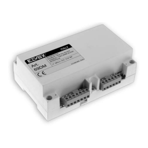
Vimar Elvox 69DM Assembly instructions

Vimar

Vimar Elvox 69DM Assembly instructions

Vimar Elvox 13F3 User manual

Vimar

Vimar Elvox 13F3 User manual

Vimar Elvox 6120 Assembly instructions

Vimar

Vimar Elvox 6120 Assembly instructions

Vimar By-alarm 01729 User manual

Vimar

Vimar By-alarm 01729 User manual

Vimar CALL-WAY User manual

Vimar

Vimar CALL-WAY User manual

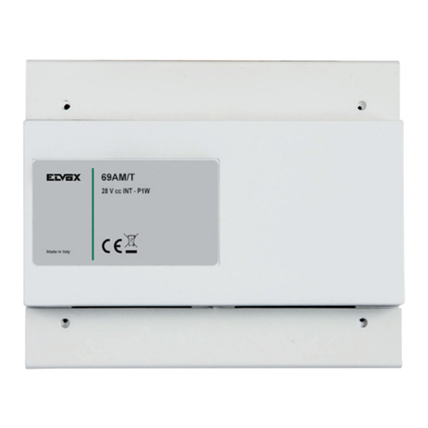
Vimar Elvox 69AM/T Assembly instructions

Vimar

Vimar Elvox 69AM/T Assembly instructions

Vimar By-alarm 01729 User guide

Vimar

Vimar By-alarm 01729 User guide

Vimar Elvox 693T Assembly instructions

Vimar

Vimar Elvox 693T Assembly instructions

Vimar Elvox 69TF User manual

Vimar

Vimar Elvox 69TF User manual

Vimar 01711 User manual

Vimar

Vimar 01711 User manual

Vimar 01515.1 User manual

Vimar

Vimar 01515.1 User manual

Vimar by-me Eikon 20589 User manual

Vimar

Vimar by-me Eikon 20589 User manual

Vimar Elvox 692I/U Assembly instructions

Vimar

Vimar Elvox 692I/U Assembly instructions

Vimar Elvox 40164 User guide

Vimar

Vimar Elvox 40164 User guide

Vimar 69DM.EN User guide

Vimar

Vimar 69DM.EN User guide

Vimar Eikon User manual

Vimar

Vimar Eikon User manual

Vimar LINEA 30495.x User manual

Vimar

Vimar LINEA 30495.x User manual

Popular Recording Equipment manuals by other brands

Kawai Standard MIDI Files Compatible Sequencer... Operation guide

Kawai

Kawai Standard MIDI Files Compatible Sequencer... Operation guide

SynOptics 3395 Command reference

SynOptics

SynOptics 3395 Command reference

Axis T6101 installation guide

Axis

Axis T6101 installation guide

ST ST25R3916-DISCO user manual

ST

ST ST25R3916-DISCO user manual

Roland XV-5080. Compatibility guide

Roland

Roland XV-5080. Compatibility guide

CED Power1401-3 Owner's handbook

CED

CED Power1401-3 Owner's handbook

Cisco WIC-2T quick start guide

Cisco

Cisco WIC-2T quick start guide

MicroRidge Gageway Pro Series user guide

MicroRidge

MicroRidge Gageway Pro Series user guide

Audioplex VCPage Doorbell Interface installation manual

Audioplex

Audioplex VCPage Doorbell Interface installation manual

Comelit 1468 Programming manual

Comelit

Comelit 1468 Programming manual

Tascam PORTASTUDIO 788 Addendum

Tascam

Tascam PORTASTUDIO 788 Addendum

Furman PS-PRO owner's manual

Furman

Furman PS-PRO owner's manual

Leightronix IncodeX One Installation, configuration, and operation manual

Leightronix

Leightronix IncodeX One Installation, configuration, and operation manual

PRESONUS Recording Interface w/ Eight Microphone Preamplifiers Version... user manual

PRESONUS

PRESONUS Recording Interface w/ Eight Microphone Preamplifiers Version... user manual

Emerson ROSEMOUNT Analytical SPS 4000 Series instruction manual

Emerson

Emerson ROSEMOUNT Analytical SPS 4000 Series instruction manual

jablotron UC-280 quick start guide

jablotron

jablotron UC-280 quick start guide

Tascam MX-2424 Quick reference guide

Tascam

Tascam MX-2424 Quick reference guide

Biamp VOCIA LSI-16 Setup and wiring guide

Biamp

Biamp VOCIA LSI-16 Setup and wiring guide

manuals.online logo
manuals.online logoBrands
  • About & Mission
  • Contact us
  • Privacy Policy
  • Terms and Conditions

Copyright 2025 Manuals.Online. All Rights Reserved.