manuals.online logo
Brands
  1. Home
  2. •
  3. Brands
  4. •
  5. Vimar
  6. •
  7. Security Camera
  8. •
  9. Vimar ELVOX 46226.312D.01 User manual

Vimar ELVOX 46226.312D.01 User manual

Viale Vicenza, 14
36063 Marostica VI - Italy
www.vimar.com
46226.312D.01
49401025A0 02 1701
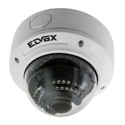
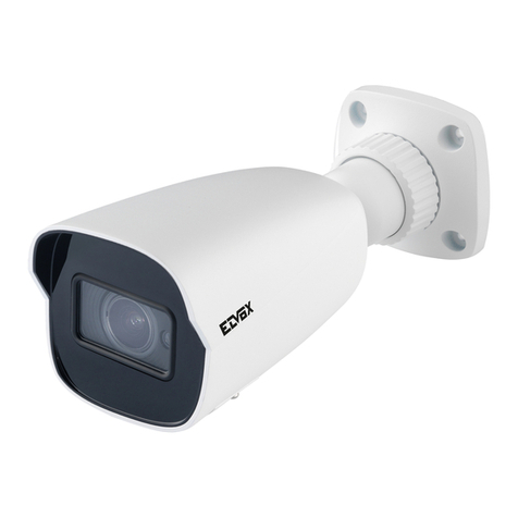
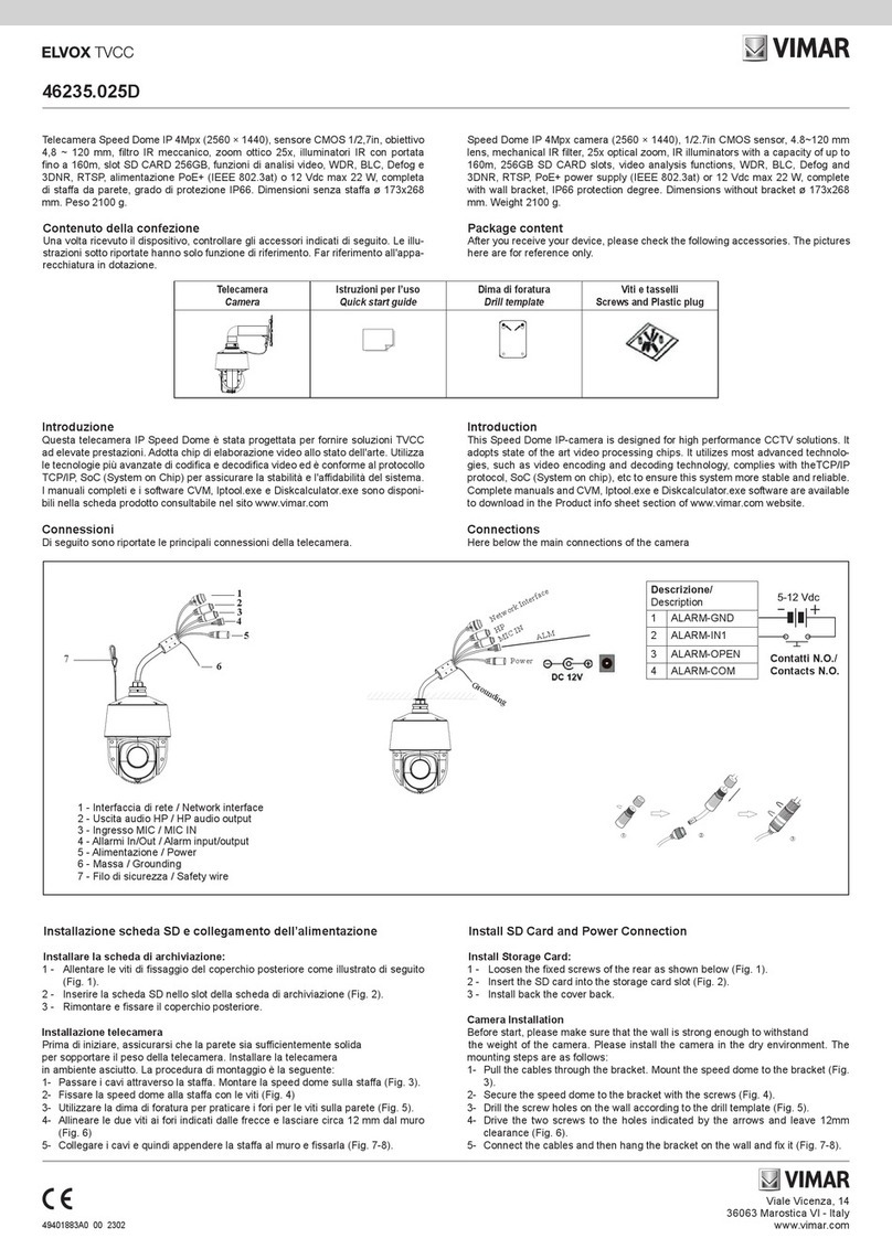
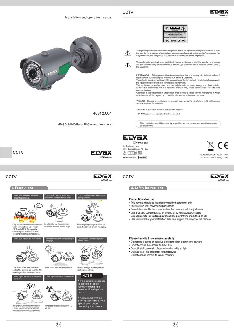
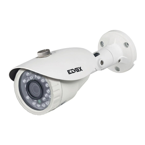
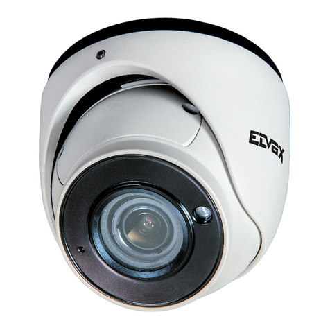
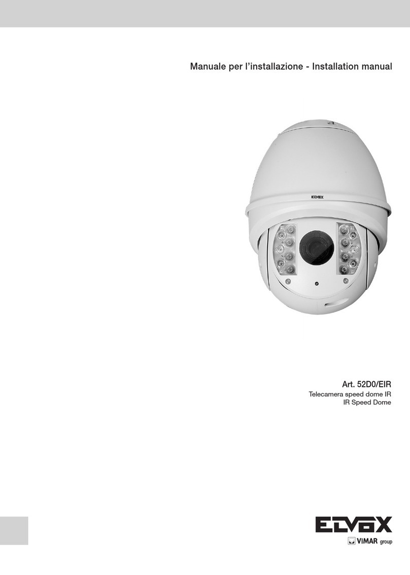
Dome IP Day & Night colour video camera, 4 Mpx resolution (2560x1440),
3.3-12 mm varifocal lens, mechanical IR filter, multi-stream H.265 and
H.264, PoE or 12 Vdc power supply, SD CARD slot, IR 20-30 m, WDR, HLC,
ROI and 3D DNR functions, Mask, Motion, HFR, DC-Iris, Smart IR, RTSP,
ONVIF protocol, degree of protection IP 66 and IK10.
Telecamera Dome IP a colori Day & Night, risoluzione 4 Mpx (2592x1520),
obiettivo varifocale 3,3-12 mm, filtro IR meccanico, H.265 e H.264
Multistream, alimentazione PoE o 12 Vdc, slot SD CARD, IR 20- 30 m,
funzioni WDR, HLC, ROI e 3D DNR, Mask, Motion, HFR, DC-Iris, Smart IR,
RTSP, protocollo ONVIF, grado di protezione IP66 e IK10.
Telecamera
Camera
Istruzioni per l’uso
Quick and start guide CD Modello
Drill template
Viti
Screws & spiles
Cacciavite
Screwdriver
Cavo di
connessione
CVBS e DC IN
CVBS & DC in cables
Cappuccio
impermeabile
Water-proof
Cap
1. Confezione
Una volta ricevuto il dispositivo, controllare gli accessori indicati di segui-
to. Le immagini valgono solo come riferimento.
1 Cavo di rete / Network Cable 6 Cavo RS485 / RS485 Cable
2 Cavo microfono / Microphone Cable 7 Cavo alimentazione / Power Cable
3Cavo cufe / Headphone Cable 8 Slot per scheda TF / TF Card Slot
4 Uscita video / Video Output 9 Foro per il reset / Reset Hole
5 Ingresso-Uscita allarme / Alarm Input-Output 10 Porta CVBS/DC IN per test / CVBS/DC IN port for testing
8
910
RESET
TF
LINK DC IN
CVBS
1
2
3
4
5
6
7
8
910
RESET
TF
LINK DC IN
CVBS
1
2
3
4
5
6
7
2. Panoramica
Questa serie di telecamere supporta obiettivi varifocali.
3. Connession/Connections
Rout er
Computer
NetworkCable
Network Cabl e
Network Cable
Network Cable
Network Cable
M odem
Internet
MICIN
Headphone
DC12V
ALM-COM
ALM-NO
ALM-IN
ALM-GND
RS485T+
RS485T-
Router
Modem
Ingresso
Microfono
12 Vdc
Internet
Computer
Cufe
Cavo di rete
Network cables
Cavo di rete
Network cables
Cavo di rete
Cavo di rete
ALM-COM
ALM-NO
ALM-IN
ALM-GND
RS485T+
RS485T-
Cavo di rete
Monitor
Headphone
Network cables
Network cable
Network
cables
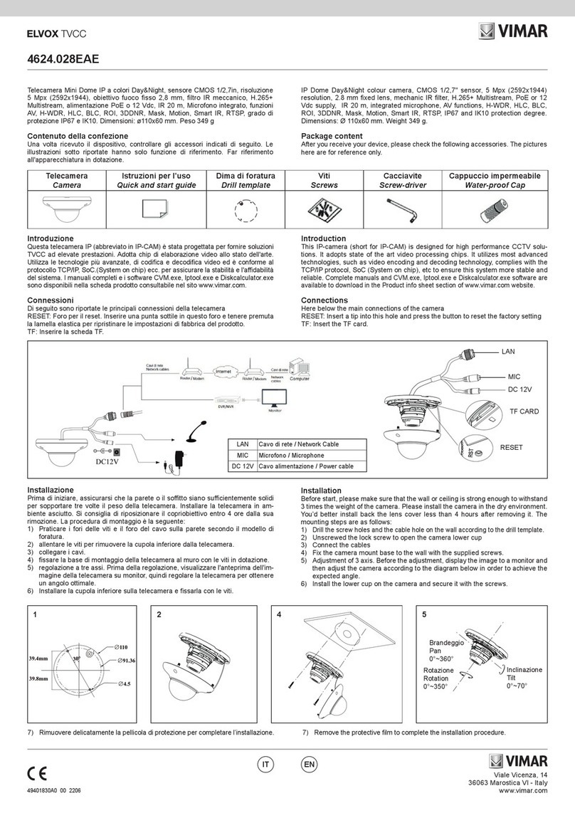
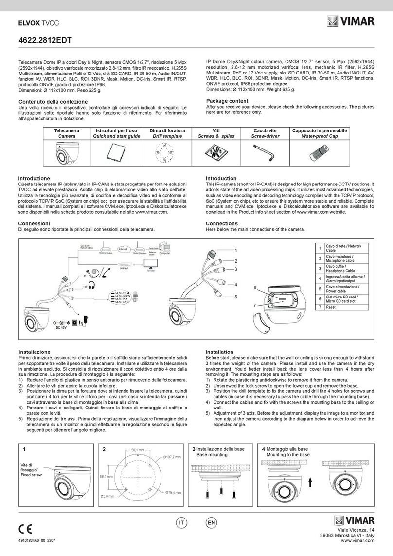
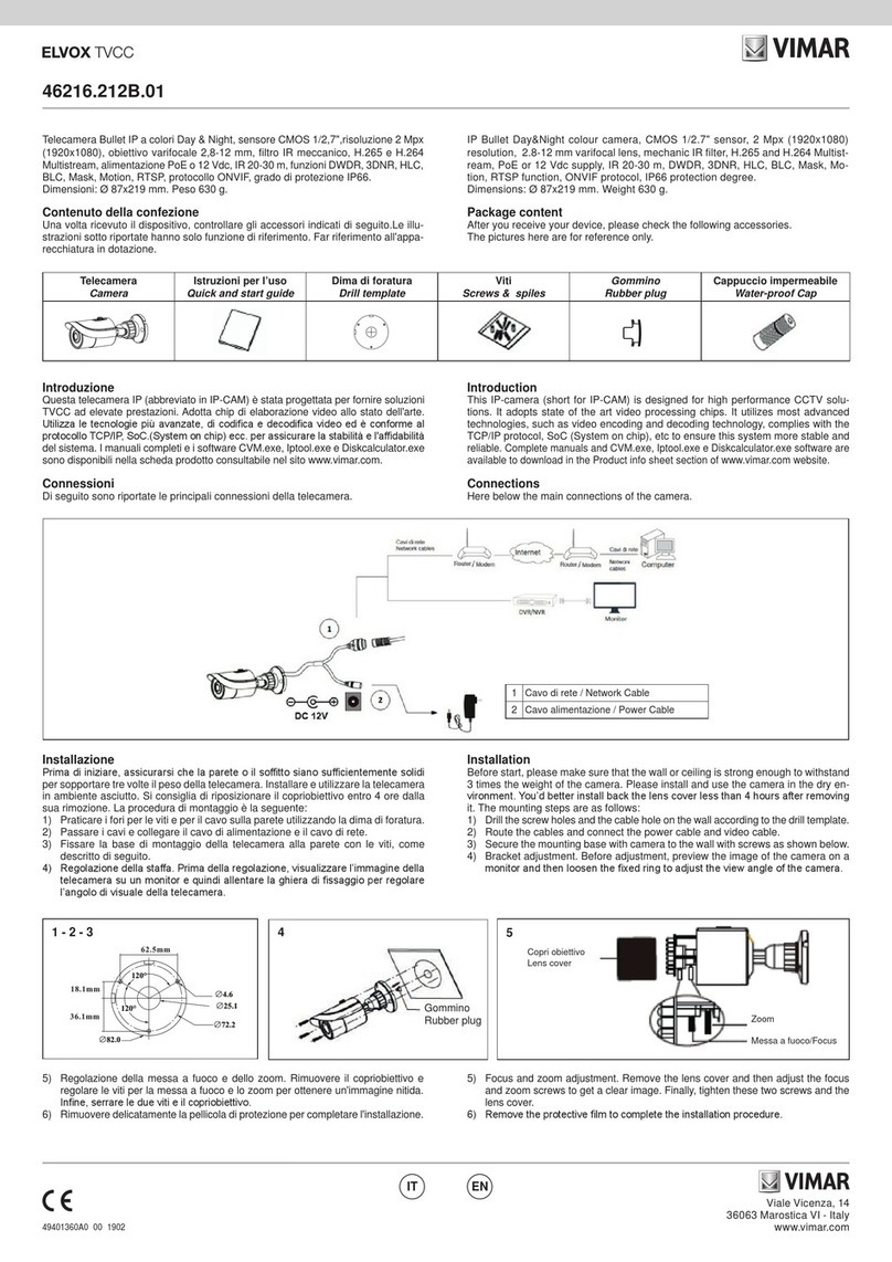
1. Package
After you receive your device, please check the following accessories.
The pictures here are for reference only.
2. Overview
This series of cameras support varifocal lens.
Viale Vicenza, 14
36063 Marostica VI - Italy
www.vimar.com
46226.312D.01
49401025A0 02 1701
Collegamento dell'allarme
- Ingresso allarme: Sono presenti un morsetto indipendente
di ingresso allarme (ALM-IN) e un morsetto di messa a terra
(ALM‑GND). Non sono richiesti sensori di tipo specico, dato che
sarà possibile selezionare la modalità NO (normalmente aperto) o NC
(normalmente chiuso). Unire i terminali di messa a terra del sensore e
della telecamera, quindi collegare il cavo del segnale del sensore alla
porta di ingresso allarme della telecamera.
- Uscita allarme: È presente un’uscita allarme 1 CH, disponibile sulle
connessioni COM e NO.
Allentare le viti del morsetto di uscita allarme. Collegare i cavi del
dispositivo di allarme rispettivamente alle connessioni NO e COM.
Inne serrare le viti. Alcuni dispositivi esterni di uscita allarme
necessitano di alimentazione.
Connessione RS485
È possibile controllare la Speed dome tramite l'interfaccia RS485.
Connessione cavo di rete
123
4. Installazione
Prima di iniziare, assicurarsi che la parete o il softto siano
sufcientemente solidi per sopportare tre volte il peso della telecamera.
Installare e utilizzare la telecamera in ambiente asciutto. Si consiglia
di riposizionare la cupola inferiore entro 4 ore dalla sua rimozione. La
procedura di montaggio è la seguente:
1) Allentare le viti per aprire la cupola inferiore, quindi allentare la vite di
bloccaggio per rimuovere la base di montaggio.
Vite di bloccaggio
Lock Screw
2) Posizionare la dima per la foratura dove si intende ssare la
telecamera, quindi praticare i 4 fori per le viti e il foro per i cavi (nel
caso si intenda far passare i cavi attraverso la base di montaggio) in
base alla dima.
4) Fissare la telecamera alla base di montaggio con la vite di bloccaggio.
3) Passare i cavi e collegarli. Quindi ssare la base di montaggio al
softto o parete con le viti.
Softto o parete
Ceiling or Wall
Alarm Connection
- Alarm Input: There is one independent alarm input port (ALM-IN)
and one grounding port (ALM-GND).There are no type requirements
for sensors. NO and NC are both available. Join the grounding ends
of the sensor and the camera and then connect the signal cable of the
sensor to the alarm input port of the camera.
- Alarm Output: There is 1 CH alarm output including COM and NO
connections.
Loosen the screws in the alarm output port. Then insert the signal
wires of the alarm output devices into the port of NO and COM sepa-
rately. Finally tighten the screws. Some of the external alarm output
devices need the power supply.
RS 485 Connection
You can control the speed dome by RS485 interfaces.
Network Cable Connection
4. Installation
Before start, please make sure that the wall or ceiling is strong enough
to withstand 3 times the weight of the camera. Please install and use the
camera in the dry environment. You’d better install back the lower dome
less than 4 hours after removing it. The mounting steps are as follows:
1) Loosen the screws to open the lower dome and then loosen the lock
screw to remove the mounting base.
2) Attach the drill template to the place where you want to x the camera
and then drill 4 screw holes and 1 cable hole (if you want to route the
cables through the mounting base) according to the drill template.
4) Fix the camera to the mounting base with the lock screw.
3) Route the cables and connect these cables. And then secure the
mounting base to the ceiling or wall with screws.
Softto o parete
Ceiling or Wall
Viale Vicenza, 14
36063 Marostica VI - Italy
www.vimar.com
46226.312D.01
49401025A0 02 1701
5) Regolazione dei tre assi. Prima della regolazione, visualizzare
l’immagine della telecamera su un monitor e quindi effettuarne la
regolazione secondo le gure seguenti per ottenere l’angolo migliore.
6) Regolare la vite di messa a fuoco e zoom per ottenere un’immagine
nitida (se la telecamera è dotata di obiettivo sso, saltare questo
passaggio).
Zoom
Messa a fuoco/ Focus
Inclinazione
0~-75° Brandeggio 0~-360°
Rotazione 0~-360°
7) Fissare la cupola inferiore sulla telecamera con le viti e rimuovere
delicatamente la pellicola di protezione per completare l’installazione.
5. Connessioni di rete IE
Come esempio, accediamo alla telecamera IP attraverso la LAN. In una
LAN è possibile accedere in due modi:
1. Accesso tramite IP-Tool;
2. Accesso diretto tramite Internet Explorer.
►Accesso alla telecamera tramite IP-Tool
1) Assicurarsi che la telecamera e il PC siano connessi alla LAN.
2) Individuare IP‑Tool nel CD e installarlo sul computer. Inne, avviare
IP-Tool come mostrato di seguito.
Mac Address
IP Address
Modify Network Parameter
Modify
CE :98 :23 :75 :35 :22
192 168 1 . 201
255 255255. 0
192168 1 . 1
Subnet Mask
Gateway
DeviceNetworkSearch
ImmediateRefresh
name
name
name
IPC
IPC
IPC
unknown
unknown
unknown
192.168.226.201
192.168.1.2
192.168.1.3
80
80
80
9008
9008
9008
255.255.
255.255.
255.255.
Modify Network Parameter
Mac Address
IP Address
Modify
CE :98 :23 :75 :35 :22
192168226. 201
255 255255. 0
192168226. 1
i
Tip: Enter the administrator password, and
then modify the network parameters.
Total Device: 3
Local IP Address:19216814Subnet Mask:2552552550Gateway: 19216811DNS͹210211966
Device Name Device Type IP AddressHttp Port Data Port Subnet
Product Model
About
Subnet Mask
Gateway
Restore IPC Default Configuration
3) Modicare l'indirizzo IP. L'indirizzo IP predenito di questa telecame-
ra è 192.168.226.201. Fare clic sulle informazioni della telecamera
elencate nella tabella sopra riportata per visualizzare le informazioni
di rete sulla destra. Modicare l'indirizzo IP e il gateway della teleca-
mera e assicurarsi che l'indirizzo di rete si trovi nello stesso segmento
della rete locale del computer. Modicare l'indirizzo IP del dispositivo
in base alla situazione specica.
Mac Address
IP Address
Modify Network Parameter
Modify
CE :98 :23 :75 :35 :22
192168 1 . 201
255 255255. 0
192168 1 . 1
Subnet Mask
Gateway
DeviceNetworkSearch
ImmediateRefresh
name
name
name
IPC
IPC
IPC
unknown
unknown
unknown
192.168.226.201
192.168.1.2
192.168.1.3
80
80
80
9008
9008
9008
255.255.
255.255.
255.255.
Modify Network Parameter
Mac Address
IP Address
Modify
CE :98 :23 :75 :35 :22
192168226. 201
255 255255. 0
192168226. 1
i
Tip: Enter the administrator password, and
then modify the network parameters.
Total Device: 3
Local IP Address:19216814Subnet Mask:2552552550Gateway: 19216811DNS͹210211966
Device Name Device Type IP AddressHttp Port Data Port Subnet
Product Model
About
Subnet Mask
Gateway
Restore IPC Default Configuration
Ad esempio, l'indirizzo IP del computer in uso è 192.168.1.4. Di conse-
guenza l'indirizzo della telecamera deve essere cambiato in 192.168.1.X.
Dopo la modica inserire la password di amministratore e fare clic sul
pulsante "Modica" per modicare l'impostazione.
Mac Address
IP Address
Modify Network Parameter
Modify
CE :98 :23 :75 :35 :22
192168 1 . 201
255 255255. 0
192168 1 . 1
Subnet Mask
Gateway
DeviceNetworkSearch
ImmediateRefresh
name
name
name
IPC
IPC
IPC
unknown
unknown
unknown
192.168.226.201
192.168.1.2
192.168.1.3
80
80
80
9008
9008
9008
255.255.
255.255.
255.255.
Modify Network Parameter
Mac Address
IP Address
Modify
CE :98 :23 :75 :35 :22
192168226. 201
255 255255. 0
192168226. 1
i
Tip: Enter the administrator password, and
then modify the network parameters.
Total Device: 3
Local IP Address:19216814Subnet Mask:2552552550Gateway: 19216811DNS͹210211966
Device Name Device Type IP AddressHttp Port Data Port Subnet
Product Model
About
Subnet Mask
Gateway
Restore IPC Default Configuration
La password predenita dell'amministratore è 123456.
4) Fare doppio clic sull'indirizzo IP, il sistema aprirà Internet Explorer per
collegare l'IP-CAM. Internet Explorer scarica automaticamente i con-
trolli ActiveX. Dopo il download viene visualizzata la nestra di acces-
so. Immettere User Name (Nome utente) e Password per accedere.
Mac Address
IP Address
Modify Network Parameter
Modify
CE :98 :23 :75 :35 :22
192168 1 . 201
255 255255. 0
192168 1 . 1
Subnet Mask
Gateway
DeviceNetworkSearch
ImmediateRefresh
name
name
name
IPC
IPC
IPC
unknown
unknown
unknown
192.168.226.201
192.168.1.2
192.168.1.3
80
80
80
9008
9008
9008
255.255.
255.255.
255.255.
Modify Network Parameter
Mac Address
IP Address
Modify
CE :98 :23 :75 :35 :22
192168226. 201
255 255255. 0
192168226. 1
i
Tip: Enter the administrator password, and
then modify the network parameters.
Total Device: 3
Local IP Address:19216814Subnet Mask:2552552550Gateway: 19216811DNS͹210211966
Device Name Device Type IP AddressHttp Port Data Port Subnet
Product Model
About
Subnet Mask
Gateway
Restore IPC Default Configuration
Il Nome Utente predenito è admin, la Password è 123456.
5) Three-axis adjustment. Before adjustment, preview the image of the
camera on a monitor and then adjust the camera according to the
gure below to get an optimum angle.
6) Adjust the Focus and Zoom screw to get a clear image (if your camera
is prime lens, please skip this step).
Pan 0-360°
Rotation 0-360°
Tilt 0-75°
7) Install the lower dome back to the camera with the screws and remove
the protection lm softly to complete the installation.
5. IE Network Connections
Here we take accessing IP camera via LAN for example. In LAN, there
are two ways to access.
1. Access through IP-Tool;
2. Directly Access through IE Browser
►Access the camera through IP-Tool
1) Make sure that the camera and the PC are well connected to the LAN.
2) Find the IP-Tool from the CD and then install it in the computer. After
that, run the IP-Tool as shown below.
3) Modify the IP address. The default IP address of this camera is
192.168.226.201. Click the information of the camera listed in the
above table to show the network information on the right hand. Modify
the IP address and gateway of the camera and make sure its network
address is in the same local network segment as the computer’s. Ple-
ase modify the IP address of your device according to the practical
situation.
For example, the IP address of your computer is 192.168.1.4. So the IP
address of the camera shall be changed to 192.168.1.X.
After modication, please input the password of the administrator and
click “Modify” button to modify the setting.
Mac Address
IP Address
Modify Network Parameter
Modify
CE :98 :23 :75 :35 :22
192168 1 . 201
255 255255. 0
192168 1 . 1
Subnet Mask
Gateway
DeviceNetworkSearch
ImmediateRefresh
name
name
name
IPC
IPC
IPC
unknown
unknown
unknown
192.168.226.201
192.168.1.2
192.168.1.3
80
80
80
9008
9008
9008
255.255.
255.255.
255.255.
Modify Network Parameter
Mac Address
IP Address
Modify
CE :98 :23 :75 :35 :22
192168226. 201
255 255255. 0
192168226. 1
i
Tip: Enter the administrator password, and
then modify the network parameters.
Total Device: 3
Local IP Address:19216814Subnet Mask:2552552550Gateway: 19216811DNS͹210211966
Device Name Device Type IP AddressHttp Port Data Port Subnet
Product Model
About
Subnet Mask
Gateway
Restore IPC Default Configuration
The default password of the administrator is 123456.
4) Double-click the IP address and then the system will pop up the IE
browser to connect IP-CAM. IE browser will automatically download
the Active X control. After downloading, a login window will pop up.
Input the user name and password to login.
Mac Address
IP Address
Modify Network Parameter
Modify
CE :98 :23 :75 :35 :22
192168 1 . 201
255 255255. 0
192168 1 . 1
Subnet Mask
Gateway
DeviceNetworkSearch
ImmediateRefresh
name
name
name
IPC
IPC
IPC
unknown
unknown
unknown
192.168.226.201
192.168.1.2
192.168.1.3
80
80
80
9008
9008
9008
255.255.
255.255.
255.255.
Modify Network Parameter
Mac Address
IP Address
Modify
CE :98 :23 :75 :35 :22
192168226. 201
255 255255. 0
192168226. 1
i
Tip: Enter the administrator password, and
then modify the network parameters.
Total Device: 3
Local IP Address:19216814Subnet Mask:2552552550Gateway: 19216811DNS͹210211966
Device Name Device Type IP AddressHttp Port Data Port Subnet
Product Model
About
Subnet Mask
Gateway
Restore IPC Default Configuration
The default user name is admin; the default password is 123456.
Viale Vicenza, 14
36063 Marostica VI - Italy
www.vimar.com
46226.312D.01
49401025A0 02 1701
6.Specifiche / Specification
Modello / Model 46226.312D.01
Telecamera /
Camera
Sensore di immagine /
Image sensor 1/3” CMOS
Pixel sensore /
Sensor pixels 2688x1520
Otturatore elettronico /
Electronic shutter 1/25 s ~ 1/100000 s
Diaframma automatico /
Auto iris DC IRIS AUTOMATICO
Illuminazione minima /
Min. illumination 0 Lux (con LED IR attivo)
Obiettivo / Lens 3,3-12 mm
Tipo di attacco / Mount type 14 mount / ø14 mount
Immagine /
Image
Compressione / Compression H264/H265/MJPEG
Risoluzione / Resolution: 4 MP (2592x1520), 2K (2560×1440),3 MP (2304×1296),1080P (1920×1080),720P (1280×720), D1,
CIF, 480×240
Frame rate: 60Hz:30 fps, 50 Hz:25 fps
Bit-rate: 64 Kbps - 10 Mbps
Codica / Encode VBR/CBR
Qualità / Quality Livello VBR 5, CBR illimitato / VBR 5 level, CBR no limit
Cong. immagine /
Image cong.
Saturazione, Luminosità, Contrasto, WDR (Via IE e client end), ROI, HLC, BLC, DEFOG /
Saturation, Brightness, Contrast, WDR (Via IE and client end), ROI, HLC, BLC, DE-FOG
Compressione audio /
Audio compression G711A
WDR REAL WDR (Hardware)
Riduzione del rumore /
Noise Reduction 3D DNR
Interfaccia /
Interface
Internet RJ45
Uscita video / Video out CVBS (BNCx1)
Audio Audio bidirezionale (MIC IN×1, Audio OUT×1) / Dual way audio (MIC IN×1, Audio OUT×1)
Archiviazione / Storage Supporto scheda TF, capacità max no a 128GB / Support TF card, max. capacity up to 128GB
RS485 Supporto / Support
Ingresso allarme / Alarm in 1 CH
Uscita allarme / Alarm out 1 CH
Funzione /
Function
Sorveglianza remota /
Remote surveillance
Browser IE, CMS per controllo da remoto /
E browser, CMS remote control
Utenti online / Online user 10 utenti, supporta la trasmissione su più ussi in tempo reale
10 users, support multi-stream real time transmission.
Protocollo di rete / Network
protocal TCP/IP, UDP, DHCP, NTP, RTSP, PPPoE, DDNS, SMTP, FTP
Protocollo interfaccia /
Interface protocal ONVIF
Archiviazione / Storage Archiviazione locale su scheda TF, archiviazione remota / TF card local storage, remote storage
Allarme intelligente / Smart
alarm Movimento, sensore / Motion, sensor
Giorno/Notte - Day/night ICR
PTZ RS485x1
PoE Sì / Yes
Range di visione notturna /
Night vision range 20-30 m
Grado IP/IK IP66/IK10
Altri /
Others
Alimentazione /
Power supply 12 Vdc/POE
Ambiente di esercizio /
Working environment -20°C ~ 50°C con umidità 10% ~ 90% / 20°C ~ 50°C 10% ~ 90% humidity

Other Vimar Security Camera manuals

Vimar ELVOX 68TU Assembly instructions

Vimar

Vimar ELVOX 68TU Assembly instructions

Vimar ELVOX 4622.2812ESA User manual

Vimar

Vimar ELVOX 4622.2812ESA User manual

Vimar ELVOX 4651.2812ES User manual

Vimar

Vimar ELVOX 4651.2812ES User manual

Vimar Elvox 46.822.036 User manual

Vimar

Vimar Elvox 46.822.036 User manual

Vimar ELVOX 4652.2812ES User manual

Vimar

Vimar ELVOX 4652.2812ES User manual

Vimar Elvox 46226.212C User manual

Vimar

Vimar Elvox 46226.212C User manual

Vimar Elvox 46812.036C User manual

Vimar

Vimar Elvox 46812.036C User manual

Vimar ELVOX TVCC 46235.015B User manual

Vimar

Vimar ELVOX TVCC 46235.015B User manual

Vimar Elvox 4621.036B User manual

Vimar

Vimar Elvox 4621.036B User manual

Vimar ELVOX 4621.2812FMA User manual

Vimar

Vimar ELVOX 4621.2812FMA User manual

Vimar Elvox 4622.2812FMK User manual

Vimar

Vimar Elvox 4622.2812FMK User manual

Vimar ELVOX TVCC 46237.KIT User manual

Vimar

Vimar ELVOX TVCC 46237.KIT User manual

Vimar ELVOX 46232.012 User manual

Vimar

Vimar ELVOX 46232.012 User manual

Vimar Elvox 46226.312EMS User manual

Vimar

Vimar Elvox 46226.312EMS User manual

Vimar ELVOX TVCC 46235.016B User manual

Vimar

Vimar ELVOX TVCC 46235.016B User manual

Vimar ELVOX 46635.036 User manual

Vimar

Vimar ELVOX 46635.036 User manual

Vimar ELVOX TVCC 4651.2812B User manual

Vimar

Vimar ELVOX TVCC 4651.2812B User manual

Vimar ELVOX TVCC User manual

Vimar

Vimar ELVOX TVCC User manual

Vimar ELVOX 4624.028EAE User manual

Vimar

Vimar ELVOX 4624.028EAE User manual

Vimar ELVOX 46CAM.136B User manual

Vimar

Vimar ELVOX 46CAM.136B User manual

Vimar ELVOX 4621.2812DA User manual

Vimar

Vimar ELVOX 4621.2812DA User manual

Vimar ELVOX 46512.036.01 User manual

Vimar

Vimar ELVOX 46512.036.01 User manual

Vimar 46222.036.01 User manual

Vimar

Vimar 46222.036.01 User manual

Vimar Elvox 46238.036 User manual

Vimar

Vimar Elvox 46238.036 User manual

Popular Security Camera manuals by other brands

Bosch LTC 1462/21 reference guide

Bosch

Bosch LTC 1462/21 reference guide

TRASSIR TR-D8121IR2W user manual

TRASSIR

TRASSIR TR-D8121IR2W user manual

Twilight PTZPRO27 user manual

Twilight

Twilight PTZPRO27 user manual

TP-Link TL-SC3230N user guide

TP-Link

TP-Link TL-SC3230N user guide

Novus NVAHD-2DN3202MV/IR-1-II user manual

Novus

Novus NVAHD-2DN3202MV/IR-1-II user manual

Novus NVAHD-2DN3202MH/IR-1-II user manual

Novus

Novus NVAHD-2DN3202MH/IR-1-II user manual

Zumimall ZS-GX2S user manual

Zumimall

Zumimall ZS-GX2S user manual

Paradox Hellas S.A. YX-542R8 user manual

Paradox Hellas S.A.

Paradox Hellas S.A. YX-542R8 user manual

Nokia Home+ Quick installation guide

Nokia

Nokia Home+ Quick installation guide

LevelOne GEMINI FCS-4051 user manual

LevelOne

LevelOne GEMINI FCS-4051 user manual

Eneo ENC-1001L Installation and operating manual

Eneo

Eneo ENC-1001L Installation and operating manual

OCO 2 Instruction

OCO

OCO 2 Instruction

Vision Tech VDA140 instruction manual

Vision Tech

Vision Tech VDA140 instruction manual

Opto Vision WTK-363 user manual

Opto Vision

Opto Vision WTK-363 user manual

OpenEye CM-511 quick guide

OpenEye

OpenEye CM-511 quick guide

Eneo IPD-78M3611M5A Quick installation guide

Eneo

Eneo IPD-78M3611M5A Quick installation guide

Eneo ISM-72F0021W0A Full manual

Eneo

Eneo ISM-72F0021W0A Full manual

Novus NVIP-2DN3032V/IR-1P user manual

Novus

Novus NVIP-2DN3032V/IR-1P user manual

manuals.online logo
manuals.online logoBrands
  • About & Mission
  • Contact us
  • Privacy Policy
  • Terms and Conditions

Copyright 2025 Manuals.Online. All Rights Reserved.