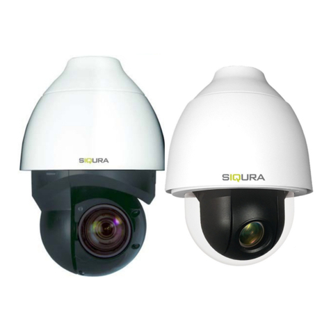
Siqura XCU Series User manual

User Manual
XCU Series
Firmware version 2.19
Rugged and reliable IP cameras for challenging environments

Page 2
Note: To ensure proper operation, please read this manual thoroughly before using the product and retain the
information for future reference.
Copyright © 2018 Siqura B.V.
All rights reserved.
XCU Series 2.19
User Manual v2 (180511-2)
AIT55
Nothing from this publication may be copied, translated, reproduced, and/or published by means of printing,
photocopying, or by any other means without the prior written permission of Siqura.
Siqura reserves the right to modify specifications stated in this manual.
Brand names
Any brand names mentioned in this manual are registered trademarks of their respective owners.
Liability
Siqura accepts no liability for claims from third parties arising from improper use other than that stated in this
manual.
Although considerable care has been taken to ensure a correct and suitably comprehensive description of all
relevant product components, this manual may nonetheless contain errors and inaccuracies. We invite you to offer
your suggestions and comments by email via t.writing@siqura.com. Your feedback will help us to further improve
our documentation.
How to contact us
If you have any comments or queries concerning any aspect related to the product, do not hesitate to contact:
Siqura B.V.
Meridiaan 32
2801 DA Gouda
The Netherlands
General : +31 182 592 333
Fax : +31 182 592 123
E-mail : sales.nl@siqura.com
WWW : http://siqura.com

Page 3
Contents
1ABOUT THIS MANUAL .............................................................................................................................. 5
2OVERVIEW ............................................................................................................................................... 6
2.1 FEATURES ..................................................................................................................................................6
2.2 DESCRIPTION ..............................................................................................................................................6
3GET ACCESS TO THE UNIT......................................................................................................................... 7
3.1 GET ACCESS VIA WEB BROWSER ......................................................................................................................7
3.2 GET ACCESS VIA DEVICE MANAGER .................................................................................................................7
3.3 GET ACCESS VIA UPNP .................................................................................................................................8
3.4 LOG ON TO THE UNIT....................................................................................................................................8
4USE THE WEB INTERFACE ......................................................................................................................... 9
5LIVE STREAM.......................................................................................................................................... 10
6CAMERA ................................................................................................................................................ 13
6.1 CAMERA MANAGEMENT.............................................................................................................................13
6.2 IMAGE SETTINGS .......................................................................................................................................14
6.2.1 Exposure ...........................................................................................................................................15
6.2.2 Zoom/Focus......................................................................................................................................17
6.2.3 White Balance ..................................................................................................................................17
6.2.4 Day/Night.........................................................................................................................................19
6.2.5 Appearance ......................................................................................................................................19
6.2.6 Enhancement....................................................................................................................................20
6.3 THERMAL SETTINGS ...................................................................................................................................20
6.3.1 Color palette.....................................................................................................................................21
6.3.2 Isotherm ...........................................................................................................................................21
6.3.3 Image mode .....................................................................................................................................21
6.3.4 Radiometry.......................................................................................................................................22
6.4 OVERLAYS ................................................................................................................................................23
6.5 STREAMING PROFILES.................................................................................................................................26
6.6 PTZ ........................................................................................................................................................28
6.7 PRIVACY MASK .........................................................................................................................................30
7EVENT .................................................................................................................................................... 31
7.1 EVENT MANAGEMENT................................................................................................................................31
7.2 CONNECTION MONITOR .............................................................................................................................31
7.3 DIGITAL I/O .............................................................................................................................................32
7.4 FTP PUSH ................................................................................................................................................33
7.4.1 Servers ..............................................................................................................................................33
7.4.2 Camera-#..........................................................................................................................................33
8RECORDING ........................................................................................................................................... 34
8.1 CAMERA-#...............................................................................................................................................34
8.2 SD CARD .................................................................................................................................................35
8.3 NAS RECORDING .......................................................................................................................................36
8.3.1 Server settings ..................................................................................................................................36
9DEVICE ................................................................................................................................................... 38
9.1 DEVICE MANAGEMENT...............................................................................................................................38
9.2 NETWORK ................................................................................................................................................40

Contents
Page 4
9.2.1 Network............................................................................................................................................40
9.2.2 Services.............................................................................................................................................41
9.3 DATE AND TIME ........................................................................................................................................42
9.4 SECURITY .................................................................................................................................................43
9.5 USER MANAGEMENT .................................................................................................................................45
9.6 SNMP ....................................................................................................................................................46
9.7 HEATER ...................................................................................................................................................47
10 DIAGNOSTICS......................................................................................................................................... 48
10.1 LOGGING .................................................................................................................................................48
11 ANALYTICS ............................................................................................................................................. 49
11.1 TAMPERING..............................................................................................................................................49
11.2 MOTION DETECTION..................................................................................................................................50
11.3 QUALITY MONITOR....................................................................................................................................50
11.4 DETECTOR................................................................................................................................................51
11.4.1 Zone and line detection................................................................................................................51
11.4.2 Hot spot detection .......................................................................................................................53
11.4.3 Flare stack monitoring .................................................................................................................54
11.5 LICENSE PLATE RECOGNITION.......................................................................................................................55
11.5.1 Reads............................................................................................................................................55
11.5.2 Camera #......................................................................................................................................55
12 ADVANCED ............................................................................................................................................ 58
12.1 DIRECT STREAMING ...................................................................................................................................58
12.2 DATA ......................................................................................................................................................59
12.3 AUDIO.....................................................................................................................................................60
12.4 RTSP ......................................................................................................................................................60
13 TROUBLESHOOTING............................................................................................................................... 61
13.1 DATE AND TIME ISSUES ...............................................................................................................................61
13.2 FTP ISSUES...............................................................................................................................................61
13.3 LOGON ISSUES ..........................................................................................................................................61
13.4 NETWORK ISSUES ......................................................................................................................................61
13.5 UPGRADE ISSUES .......................................................................................................................................62
13.6 VIDEO ISSUES............................................................................................................................................63
13.7 HEATER ISSUES..........................................................................................................................................63
13.8 WEBPAGE ISSUES.......................................................................................................................................63
ACKNOWLEDGEMENTS .................................................................................................................................. 64

Page 5
Chapter 1
1About this manual
What's in this manual
This is version 2 of the user manual for the XCU Series. This document describes:
How to get access to the unit
How to communicate with the unit
How to operate the unit
How to configure the settings of the unit
Where to find more information
Find product specific datasheets, manuals, EU Declarations of Conformity and firmware updates
at http://siqura.com. Make sure that you have the latest version of this manual.
Who this manual is for
These instructions are for all professionals who will configure and operate this product.
What you need to know
You will have a better understanding of how this product works if you are familiar with:
Camera technologies
CCTV systems and components
Ethernet network technologies and Internet Protocol (IP)
Windows environments
Video, audio, data, and contact closure transmissions
Video compression methods
Why specifications may change
We are committed to delivering high-quality products and services. The information given in this
manual was current when published. As we continuously seek to improve our products and user
experience, all features and specifications are subject to change without notice.
We like to hear from you!
Customer satisfaction is our first priority. We welcome and value your opinion about our products
and services. Should you detect errors or inaccuracies in this manual, we would be grateful if you
would inform us. We invite you to offer your suggestions and comments via
t.writing@siqura.com. Your feedback helps us to further improve our documentation.
Acknowledgement
This product uses the open-source Free Type font-rendering library. The Open Source Libraries
and Licenses document, available at http://siqura.com, gives a complete overview of open
source libraries used by our video encoders and IP cameras.

Page 6
Chapter 2
2Overview
In This Chapter
Features ........................................................................... 6
Description........................................................................ 6
2.1 Features
XCU Series
Single or dual imager
4x or 10x zoom full-HD optical camera
Complete range of uncooled thermal imagers
Corrosion-free 316L stainless-steel housing
Compact and robust
Plug & play
Nano-coated optical window
IP66/67
ONVIF profile S compliant
Perimeter Intrusion Detection
2.2 Description
The XCU Series is designed to operate in harsh and aggressive environments. Typical
applications are found in the heavy industry, in traffic, tunnels, waterways, waste treatment and
even in corrosive environments like the marine. The XCU Fusion combines a full-HD ultra-low
light imager with an uncooled thermal imager for both day and night vision, while the XCU
Compact can be fitted with either the low-light imager or a thermal imager.

Page 7
Chapter 3
3Get access to the unit
From a standard browser on your PC, you can connect to the web interface of the unit. Use the
webpages to view live video over the network and configure the settings of the unit. This chapter
explains how to open the web interface in your browser.
In This Chapter
Get access via web browser ................................................ 7
Get access via Device Manager............................................ 7
Get access via UPnP........................................................... 8
Log on to the unit .............................................................. 8
3.1 Get access via web browser
Connect to the unit from your web browser
1 Open your web browser.
2 Type the IP address of the unit in the address bar.
If no DHCP server is found on the network, the unit will revert to its factory-set IP address.
This is the same IP address as that found on the sticker on the housing of the camera.
3 Press ENTER.
The Live Stream page is opened.
- or -
If user accounts exist on the unit, you are directed to the login page (see "Log on to the unit"
on page 8).
3.2 Get access via Device Manager
Device Manager is a Windows-based software tool that you can use to manage and configure our
cameras and video encoders. The tool automatically locates these devices on the network and
offers you an intuitive interface to set and manage network settings, configure devices, show
device status, and perform firmware upgrade.
Install Device Manager
1 Download the latest version of Device Manager at http://siqura.com.
2 Double-click the setup file.
3 Follow the installation steps to install the software.
Connect to the unit via Device Manager
1 Start Device Manager
The network is scanned.
Detected devices appear in the List View pane.
2 If multiple network adapters exist, select the appropriate adapter to scan the network that
you wish to connect to.
3 To perform a manual search, click the Rescan button.

Get access to the unit
Page 8
3.3 Get access via UPnP
Universal Plug and Play (UPnP) support is enabled by default on the unit. With the UPnP service
enabled in Windows, you can get access to the unit from Windows Explorer.
Connect to the unit via UPnP
1 In Windows Explorer, open the Network folder.
Detected devices in the same subnet as the computer are displayed, including codecs and
cameras with UPnP support.
2 Double-click the unit that you want to connect to.
The Live Stream page is opened.
- or -
If user accounts exist on the unit, you are directed to the login page (see "Log on to the unit"
on page 8).
3.4 Log on to the unit
By default, users can freely open the web interface of the camera. They are not required to log
on.
User authentication
If user accounts have been created and user authentication is activated, you encounter an
authentication box when you connect. You are prompted to supply your user name and
password. Only users with a valid account can log on.
Log on to the unit
1 In User Name, type your user name.
User name and password are case sensitive.
2 In Password, type your password.
3 Click Log In.
Use strong passwords
CAUTION: MAKE SURE YOU CREATE AN ADMIN ACCOUNT WHEN YOU OPEN THE WEB
INTERFACE FOR THE FIRST TIME. TO KEEP THE ACCOUNT SAFE, SET A STRONG, COMPLEX
PASSWORD. THIS HELPS TO PREVENT UNAUTHORISED ACCESS.
Create a strong password
Use at least eight characters
Do not include your real name, user name, company name, or other personal information
Do not use complete words that can be found in a dictionary
Use a random combination of at least two of the following categories: upper case letters,
lower case letters, numbers and special characters
Note: For better protection, especially in high-security systems, we advise you to change the
password at regular intervals.

Page 9
Chapter 4
4Use the web interface
The built-in web interface makes it easy to operate and configure your product over the network.
This section describes the layout and main features shared by the webpages.
Embedded Help
Help topics embedded in the webpages provide context-sensitive user assistance. For
information about items and settings found on a page, click the question mark (Show help) in the
Title bar of the page.
Note: The Embedded Help topics offer generic Help information for a range of Siqura products.
Whether or not a described feature, mode or setting is available on the unit at hand depends on
the model you purchased.
Home page
The Live Stream page is the home page of the unit. It is opened after successfully connecting to
the web interface.
Note: Out of the box, the unit is freely accessible. You are not prompted to log on. To prevent
unauthorised access, we recommend that you implement user authentication. This is done by
creating user accounts and activating user login. For more information, see User Management.
Menu
Use the vertical menu on the left to navigate the web interface. Clicking a menu entry opens a
page or a submenu.
Nice to know
To find a specific webpage quickly, type its name in the search-as-you-type box above the menu.
Layout
Webpages have a single-page layout or content is organised across a number of tabs. A tab
contains related commands and settings. The title of the active tab is highlighted and underlined.
Previews
Pages such as Live Stream, Image Settings, and Overlays include a camera preview. You use it
to view live video or determine the effect of your settings when you make changes.
Revert button
A Revert button appears when you adjust specific settings. It lets you undo your changes. The
button is available until you leave the webpage.
Restore the setting to its original state (at the time of opening the webpage).

Page 10
Chapter 5
5Live Stream
Functions available on the Live Stream page are model-based.
View and record live video
Take snapshots
Turn on the washer and wiper
Pan and tilt the camera
Adjust the zoom, focus and iris
Layout
The Live Stream page is taken up entirely by the preview pane. This is where you can see video
from the sensor(s) inside the unit.
Dual preview
On hybrid models, the page is opened in dual-preview mode with video from the optical sensor
shown on the left and video from the thermal sensor on the right. Either of the previews can be
brought to the foreground by going to single-preview mode. Use the direction buttons which
appear when moving your mouse pointer over the preview pane.
Show previous/next preview
Show preview associated with selected option button
Toolbar
The buttons in the upper-right corner vary, based on your model.
Hide PTZ controls Show PTZ controls
Wiper on
Wiper off
Wash
Take snapshot
Start recording Stop recording
Full-screen
Close full-screen
PTZ controls
When viewing video from the optical sensor in single-view mode, PTZ controls can be displayed
in the lower-left corner. This is done by clicking Show PTZ controls in the toolbar. Note that this
button is hidden when PTZ control is disabled. The function can be enabled on the PTZ page.
Important: In the web interface and in this manual, these controls are referred to as "PTZ
controls". Note, however, that fixed camera models do not have pan/tilt (PT) functionality. The
zoom (Z) function is supported though - that is, if PTZ control is enabled.

Live Stream
Page 11
Use the wiper
Clicking Wiper on activates the wiper function on the unit. The wiper remains active until you
click Wiper off or until the time-out period (default: 5 s) expires.
Use the washer
Clicking Wash starts a washer sequence. The camera temporarily moves to the position required
for the washer function and then returns to its previous position.
Take a snapshot
It is possible to take a snapshot of the video in the preview.
Click Take snapshot.
The picture is saved in JPG format to the designated folder.
The file name includes the camera name and date/time information.
Record a live stream
A video stream shown in the preview can be recorded and downloaded to your PC.
1 Click Start recording.
The button flashes red to show you started a recording.
2 To stop the recording, click Stop recording.
The recording is saved in AVI format to the designated folder.
The file name includes date/time information.
Enter full-screen mode
For better observation, you may want to enter full-screen mode.
Click Full-screen.
The preview fills the entire screen.
Clicking Close full-screen or pressing [Esc] on your keyboard takes you back to standard
mode.
Video streaming
Video streaming can be started and paused with the Play and Pause buttons in the centre of the
preview. These buttons are available when the PTZ controls are hidden.
Play live video stream
Pause live video stream
Pan/Tilt the camera
A PTZ camera connected to the unit can be controlled from the Live Stream page.
1 Go to the PTZ page to make sure that PTZ control is enabled for the camera.
2 If the PTZ controls are hidden, click Show PTZ controls.
3 To pan/tilt the camera, drag your mouse pointer across the preview in the direction you
need.
Clicking in the preview also moves the camera.
Nice to know
In case of a power failure, the unit automatically resumes its prior position when it is powered on
again.

Live Stream
Page 12
Adjust zoom, focus, and iris
To zoom the camera or adjust the focus and iris, use the sliders in the lower-left corner for
manual adjustment. Drag the slider to the left or right and watch the preview until you achieve
the desired effect. For instant automatic focus adjustment, click the Focus now button.
Create a PTZ preset
Camera positions can be stored as PTZ presets.
1 Pan, tilt, zoom and focus the camera as needed.
2 Click Store current position as preset (the Star button).
The preset is added to the list with a number to identify it.
3 Type a descriptive name in the Preset text box.
You can also name and rename presets on the PTZ page.
Recall a PTZ preset
Camera positions stored as PTZ preset can be recalled.
In the PTZ preset list, click the required preset.
The camera adopts the recorded position.
Delete a PTZ preset
Camera positions stored as a PTZ preset can be deleted when no longer needed.
1 In the PTZ preset list, click the preset you want to delete.
2 Click Delete preset (the Recycle button).
Note that a deleted preset is irretrievably lost! You are therefore asked to confirm the
deletion.
You can delete multiple presets in one go on the PTZ page.

Page 13
Chapter 6
6Camera
In This Chapter
Camera Management ......................................................... 13
Image Settings.................................................................. 14
Thermal Settings ............................................................... 20
Overlays........................................................................... 23
Streaming Profiles.............................................................. 26
PTZ.................................................................................. 28
Privacy Mask ..................................................................... 30
6.1 Camera Management
Camera Management is where you can give the camera a name, change the aspect ratio, set the
video output mode, and turn on mirrored horizontal view, mirrored vertical view and digital
zoom. On hybrid models, there are separate tabs for optical and thermal camera management
settings.
Name
Type a unique, descriptive name in the Name box for easy identification of the unit on the
network. The name can be enabled as an overlay so that it is visible in the web interface previews
and in video streams transmitted by the unit.
Aspect ratio
This setting lets you adjust the proportional relationship between the width and the height of the
preview images shown in the web interface.
Output mode
Depending on the configuration of your camera, the unit can stream high-definition video
(1080p) at 25 or 30 frames per second (fps) or at 7.5 or 8.33 fps. Note that the mode selected
here determines the available frame rates on the Streaming Profiles page. For optical sensors, it
is recommended to select an output mode with which the frequency of the local power grid is an
exact multiple of the frame rate. When used in an area with 50 Hz power, for example, it is
recommended to use 25 fps, while 30 fps is best in areas with 60 Hz power.
Mirror horizontal
This function flips the image horizontally to create a mirrored effect.
Nice to know
In a control room, this function can be used to make traffic go in the same direction on all
monitors, which is less fatiguing for the operators.

Camera
Page 14
Mirror vertical
This function flips the image vertically to create a mirrored effect.
Digital zoom
Note: Availability of this feature depends on the model at hand.
Digital zoom makes it possible to zoom further in digitally on the image when the camera has
reached the full optical zoom level. The camera enlarges the area at the centre of the image and
trims away the edges. Image quality is reduced when you use digital zoom.
6.2 Image Settings
Layout
The Image Settings page is made up of the preview and a semi-transparent settings pane which
partly covers the preview. The settings pane can be lowered to bring the preview to the
foreground.
Lower the settings pane
Click the down arrow at the top of the transparent pane to lower it.
Raise the settings pane
Click the horizontal bar under the preview to raise the settings pane.
PTZ controls
The PTZ controls can be overlaid on the preview, as described for the Live Stream page. Use the
PTZ button in the upper-right corner to display/hide the controls.
Tabs
The image settings are grouped across multiple tabs on the Settings pane.
Profiles
Above the Image Settings tabs you find the Profiles section. Combinations of settings made on
the Image Settings page can be saved here as profiles, to be used for specific applications.
Create a profile
1 In the Profile section at the top of the Settings pane, click the leftmost button to open the
Profile list.
2 Select the profile you want to use as a basis for the new profile.
3 On the Image Settings tabs, configure the settings specific for the new profile.
4 Click New.
5 In Profile name, type a descriptive name for the profile.
6 Click Save.
The profile you started with, plus your changes are saved under the new name.
The new profile is added to the user section of the Profile list.
Apply a profile
1 In the Profile section, click to open the Profile list.
2 Click the profile you need.
The camera view is updated and adopts the settings of the selected profile.

Camera
Page 15
Delete a profile
Important: Note that a profile that you delete cannot be retrieved!
1 In the Profile section, click Select profile(s) to delete.
2 In the user section of the Profile list, select the check box of the profile that you want to
delete.
A profile that is currently active does not have a check box.
Unlike profiles created by the user, factory profiles cannot be deleted.
3 Click Delete profile.
6.2.1 Exposure
Exposure is the amount of light received by the image sensor and is determined by how wide you
open the lens diaphragm (iris adjustment), by how long you keep the sensor exposed (shutter
speed), and by other exposure parameters.
Note: Exposure modes and settings on this page vary from model to model.
Exposure mode
Use this list to select the exposure mode.
Auto
Shutter speed, iris and gain are controlled automatically based on the ambient light level.
Shutter priority
The shutter speed takes main control of the exposure. Iris and gain are adjusted
automatically.
Iris priority
The size of the iris opening (aperture) takes main control of the exposure. The shutter time
and gain are adjusted automatically. The iris can be set manually.
Bright
The shutter speed keeps its current value. Using the Bright slider, you can set a combination
of gain and iris. This gives you a single control to adjust the exposure.
Manual
Shutter speed, iris and gain can be adjusted independently according to the ambient light
level.
Actual shutter
Shows the current shutter time with the selected exposure mode.
Minimum shutter time
Use this list to adjust the minimum shutter time. Longer shutter times result in more motion blur,
but they admit more light to the sensor.
Maximum shutter time
Use this list to adjust the maximum shutter time. Shorter shutter times reduce motion blur, but
they admit less light to the sensor.
Auto slow shutter
Select Enable to allow shutter times slower than the frame time. With this function enabled, the
camera lowers the frame rate of the camera in low-light conditions. This reduces the noise level,
but results in fewer frames per second.

Camera
Page 16
Manual shutter
Use this list to adjust the shutter speed. Decreasing this value causes the camera sensor to pick
up less light, but reduces motion blur.
Actual iris
Shows the actual aperture size of the lens (iris) with the selected exposure mode.
Manual iris
Use this slider to adjust the iris. Increasing this value reduces the amount of light reaching the
sensor of the camera, but increases the depth of field of the image.
Actual gain
Shows the current amount of gain with the selected exposure mode.
Maximum auto gain
Use this slider to adjust the maximum gain that can be used by the camera. A higher gain level
results in more noise in the image.
Manual gain
Use this slider to adjust the gain. Increasing the gain results in a brighter picture but also
produces more picture noise.
Manual brightness
Aided by the visual feedback from the camera view, use this slider to adjust the gain and iris
values in one go. The Actual gain and Actual iris values are updated as you move the slider.
EV compensation
Use this function to compensate the exposure value (EV).
Selecting a positive value produces a brighter picture but it may cause overexposure. You
can also consider using the Highlight correction function to get more brightness.
Selecting a selecting a negative value produces a darker picture but it may cause
underexposure. You can also consider using the Wide dynamic range function to get more
darkness.
Wide dynamic range
The wide dynamic range (WDR) function helps the camera provide clear images when there are
both very bright and very dark areas simultaneously in the field of view. WDR balances the
brightness level of the whole image to provide clear images with details. To prevent the loss of
scene details, bright areas are not saturated and dark areas are not too dark.
Wide dynamic range mode
Use this function to select the wide dynamic range mode:
Multi exposure
The camera makes multiple exposures for the same image. Brighter areas of the image will
be captured using shorter exposure times and darker areas of the same image will be
captured using longer exposure times. This option will result in an excellent wide dynamic
range, but possibly with some 'ghosting' for fast-moving objects.
DWDR
The camera makes only one exposure for each image and will digitally compensate for
brighter and darker areas of the image.

Camera
Page 17
Wide dynamic range level
Use this function to adjust the level of WDR compensation.
Backlight compensation
Backlight compensation (BLC) brings more detail to the dark areas of an object when a strong
light source shining on it from behind makes it too dark to be seen clearly. To prevent the object
from appearing as a silhouette, the exposure of the entire image is adjusted to achieve a usable
light level for the object in the foreground.
Highlight correction
A small but very bright part of the image (for example, headlights of a car or the reflection of the
sun in a window) can cause the entire image to become underexposed. Setting the Highlight
correction function to Low, Mid or High compensates for exposure by strong sources of lights to
enhance the overall image quality. This makes it possible to easily read the number of vehicles
and number plates in an indoor parking area or outdoors at night.
6.2.2 Zoom/Focus
Note: Availability of this feature depends on the model at hand.
Auto focus mode
The Auto focus (AF) function provides two modes to automatically adjust the focus position.
Normal
This is the normal mode for AF operations.
Interval
Use Auto focus interval mode to set the interval between AF movements. If there are
frequent changes in the camera scene you may want to set a longer interval to prevent
frequent AF movements. The time intervals for AF movements and for the timing of the
stops can be set in one-second increments using the Auto focus move time setting. The
default setting for both is set to five seconds.
Auto focus sensitivity
The switching of AF sensitivity can be set.
Normal
Reaches the highest focus speed quickly. Use this when shooting a subject that moves
frequently. Usually, this is the most appropriate mode.
Low
Improves the stability of the focus. When the lighting level is low, the AF function does not
take effect, even though the brightness varies, contributing to a stable image.
Adjust zoom and focus
To zoom the camera or adjust the focus, use the sliders for manual adjustment. Drag the slider
to the left or right and watch the preview until you achieve the desired effect. For instant
automatic focus adjustment, click the Focus now button.
6.2.3 White Balance
Note: Available white balance modes and settings on this page vary from model to model.
A camera needs to measure the quality of a light source and create a reference colour
temperature in order to calculate all the other colours. The unit for measuring this ratio is in
degree Kelvin (K). Users can select one of the White Balance control modes, according to the
operating environment. The table below provides the colour temperatures of some light sources
as a general reference.

Camera
Page 18
Light source Colour temperature in °K
Cloudy sky 6000 to 8000
Noon sun and clear sky 6500
Household lighting 2500 to 3000
75 W Light bulb 2820
Candle flame 1200 to 1500
White balance
A variety of white balance modes is available to correct the colour of different types of light.
When you select a mode, the effect of the setting is visible in the preview and the Actual white
balance blue and Actual white balance red values (unavailable in Manual mode) are also
updated.
Auto
Using colour information from the entire screen, the camera detects a colour temperature
range and calculates an optimal white balance. It corrects the colours using the colour
temperature radiating from a black subject based on a range of values from 2500 K to 7500
K.
Auto tracing
The camera continuously adjusts the colour balance to changes in the colour temperature
which may occur. Auto tracing is suitable for environments with light sources ranging from
2000 K to 10000 K.
Auto outdoor
This is an auto white balance mode specifically for outdoor environments. It allows you to
capture images with a natural white balance in the morning and evening.
Auto sodium lamp
The camera automatically compensates for sodium vapour lighting to restore objects to their
original colour.
Auto outdoor sodium lamp
This is an auto white balance mode specifically for outdoor sodium vapour lighting, as used
in street lamps, for example.
Indoor
3200 K Base mode. The camera adjusts the white balance to a colour temperature range
suitable for indoor lighting conditions.
Outdoor
5800 K Base mode. The camera adjusts the white balance to a colour temperature range
suitable for outdoor lighting conditions.
Sodium lamp
This is a fixed white balance mode specifically for sodium vapour lamps.
One push
Sets the white balance to the optimal white balance currently calculated by the camera.
Manual
Aided by the visual feedback from the camera view, you can change the white balance value
manually by adjusting the White balance blue and White balance red sliders.
Actual white balance blue
Value showing the current white balance blue level.
Actual white balance red
Value showing the current white balance red level.
White balance blue
Adjusts the white balance blue level.

Camera
Page 19
White balance red
Adjusts the white balance red level.
Adjust white balance
Sets the white balance to the optimal white balance currently calculated by the camera.
6.2.4 Day/Night
Note: Availability of this feature depends on the model at hand.
An infrared (IR) cut-filter can be removed from the image path for increased sensitivity in
low-light environments. The filter can automatically engage depending on the ambient light,
allowing the camera to be effective in day/night environments.
IR cut filter
The IR cut filter can be set to Auto, On, and Off.
Auto
Auto mode automatically switches the settings needed for attaching or removing the IR cut
filter. With a set level of darkness, the IR cut filter is automatically disabled (Off), and the
infrared sensitivity is increased. With a set level of brightness, the IR cut filter is
automatically enabled (On).
On
The IR cut filter is enabled. Use this mode when there is sufficient light (day mode).
Off
The IR cut filter is disabled. The camera is more sensitive, especially to infrared light. The
image becomes black and white.
IR cut filter threshold
In dark conditions (night time, iris extremely closed or extremely short shutter times), the gain
of the camera will increase. Use the IR cut filter threshold slider to determine at which gain level
the IR cut filter should be removed to allow more light to reach the camera sensor.
High sensitivity
Increases the maximum gain, which makes it possible to produce a brighter output even in a
darker environment.
6.2.5 Appearance
Brightness
Use this function to adjust the brightness level of the video images to your viewing conditions.
Contrast
Use this function to adjust the contrast level of the video images to your viewing conditions.
Sharpness
Use this function to adjust image sharpness to your viewing conditions.
Color saturation
Use this function to adjust the intensity (purity) of the colours in the video images.

Camera
Page 20
Hue
Use this function to enhance the colours in the video images if they do not look natural.
6.2.6 Enhancement
Note: Settings on this page vary from model to model.
Stabilizer
The camera system can provide image stabilisation to compensate for small amounts of camera
shake. Available options: Off, On, and Hold. Select Hold if you want to keep the current image
steady.
High resolution
This mode enhances edges and produces images of higher definition.
Noise filter
The NR function can remove noise (both random and non-random) to provide clearer images.
You can control the level of noise reduction with the Noise filter strength slider.
Noise filter strength
Sets the level of noise reduction. The noise reduction effect is applied in levels based on the gain
and this setting value determines the limit of the effect. In bright conditions, changing the noise
reduction level does not have any effect. This function is available if Noise filter is selected.
Defog
Enhances low-contrast images - in foggy weather conditions, for example - to make them stand
out more clearly. Available levels: Off, Low, Medium, and High.
Highlight mask level
Use this function to mask extremely bright parts of the image with a grey colour.
Picture effect
Includes the following modes.
None
Does not apply any picture effect.
Negative art
Reverses negative and positive. Black, white, and colours are reversed.
Black and white
Produces a black and white (monochrome) image.
6.3 Thermal Settings
Note: Availability of this feature depends on the model at hand.
The Thermal Settings page is where you configure the settings for video from the thermal
sensor. Changes you make are immediately applied and shown in the preview.
Table of contents
Other Siqura Security Camera manuals
Siqura
Siqura CD820 Series User manual
Siqura
Siqura CD820F1 User manual
Siqura
Siqura MSD620 User manual
Siqura
Siqura HSD622 User manual
Siqura
Siqura BC820H1-SFP User manual
Siqura
Siqura pd1103 User manual
Siqura
Siqura HSD820 Series User manual
Siqura
Siqura FD12 Owner's manual

Siqura
Siqura SA-BL37 User manual
Siqura
Siqura HSD626EXP User manual
Siqura
Siqura BL2005M1-EI User manual
Siqura
Siqura FD820MI-SFP User manual
Siqura
Siqura PD910 User manual
Siqura
Siqura PD1103Z2-E User manual
Siqura
Siqura 1002 Series User manual

Siqura
Siqura PD910 User manual
Siqura
Siqura MSD622 User manual

Siqura
Siqura HD18EXP User manual
Siqura
Siqura FD2002M1-EI User manual
Siqura
Siqura BL2002M1-EI User manual
