manuals.online logo
Brands
  1. Home
  2. •
  3. Brands
  4. •
  5. Vimar
  6. •
  7. Security Camera
  8. •
  9. Vimar ELVOX TVCC 46235.020CI User manual

Vimar ELVOX TVCC 46235.020CI User manual

Viale Vicenza, 14
36063 Marostica VI - Italy
www.vimar.com
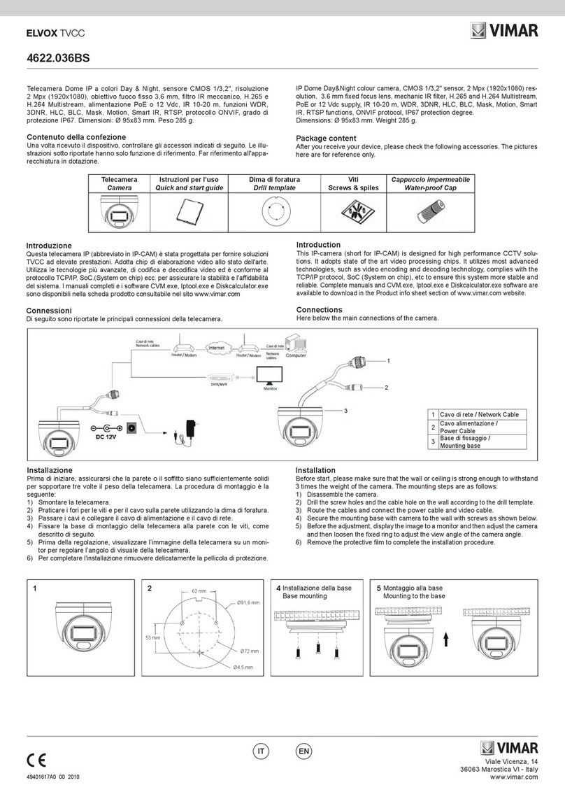
46235.020CI
49401247A0 01 1701
ENIT
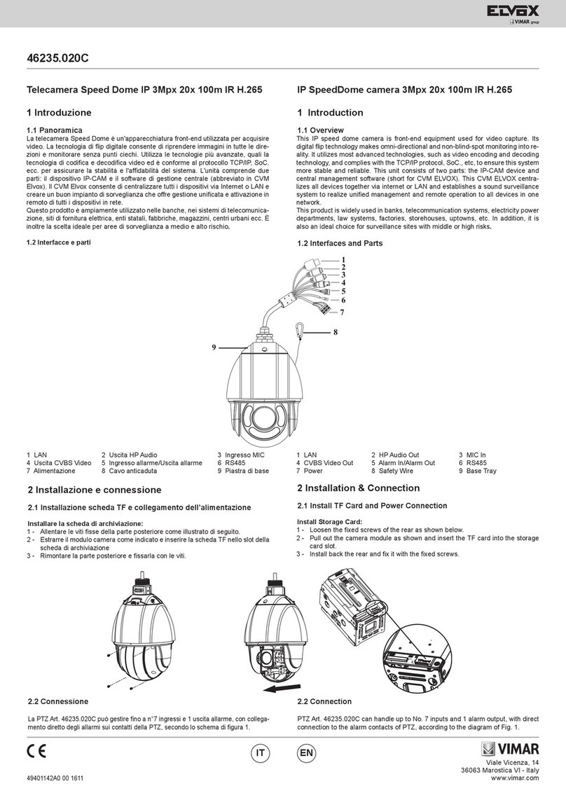
Installazione scheda TF e collegamento dell’alimentazione
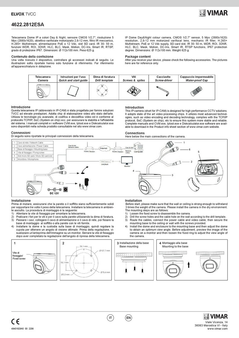
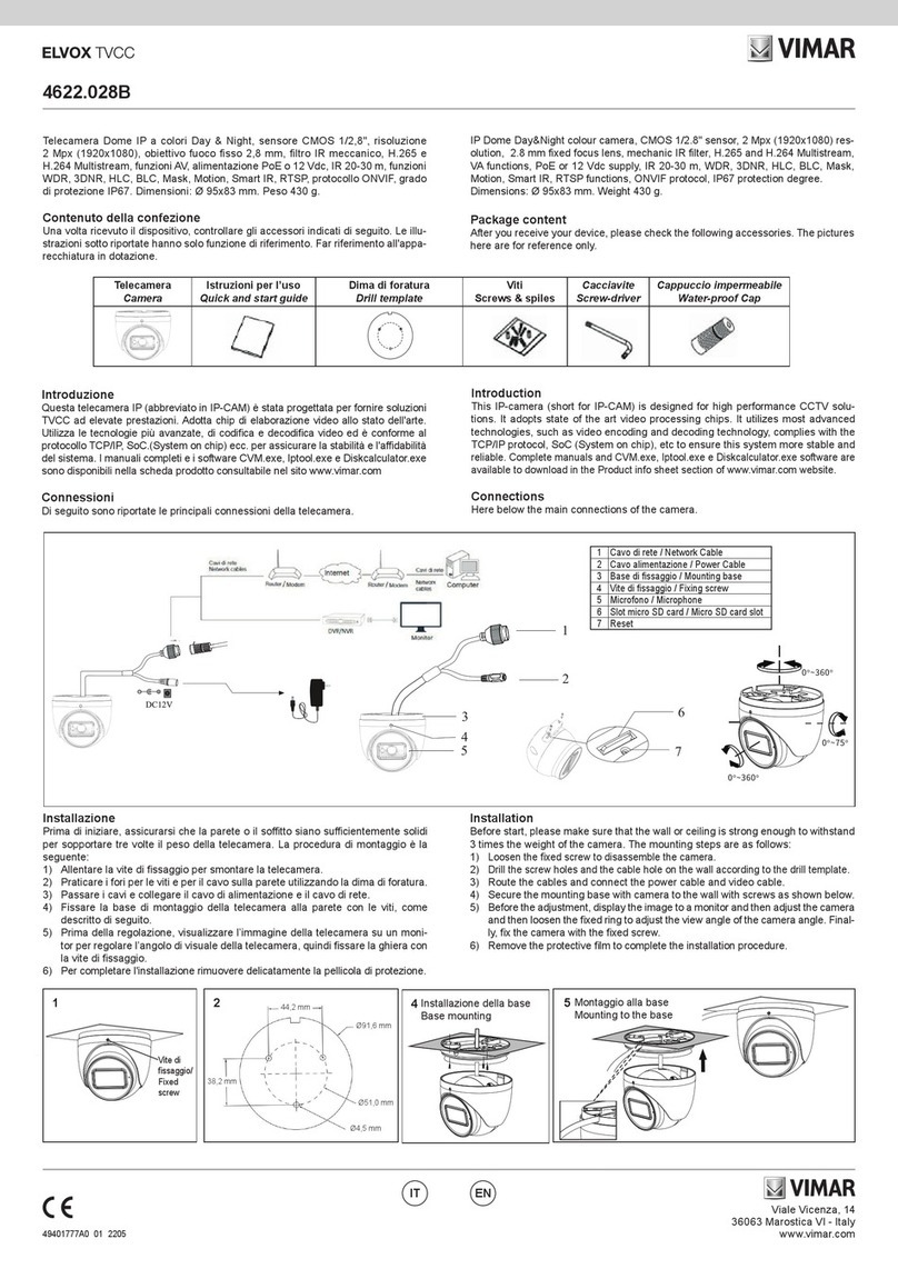
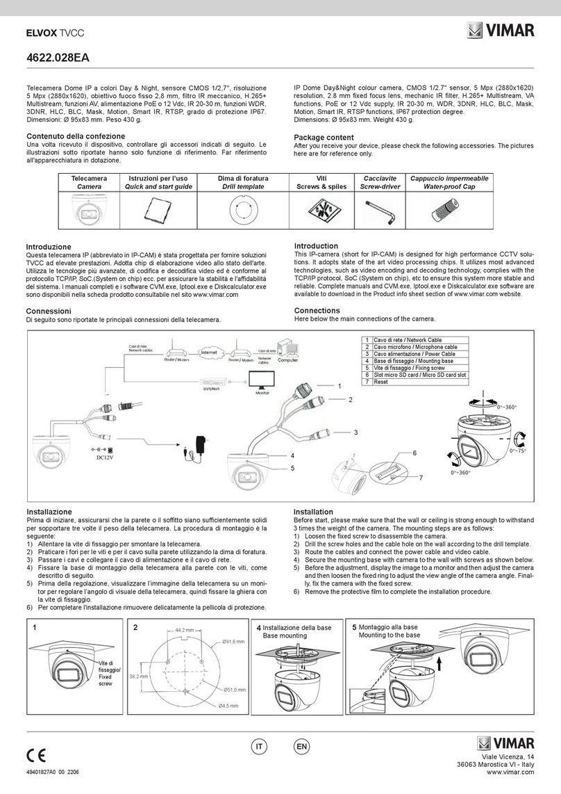
Installare la scheda di archiviazione:
1 - Allentare le viti sse come illustrato di seguito (Fig. 1).
2 - Inserire la scheda TF nello slot della scheda di archiviazione (Fig. 2).
3 - Rimontare la cupola.
Installazione telecamera
Prima di iniziare, assicurarsi che la parete o il so󰀩tto siano su󰀩cientemente solidi
per sopportare tre volte il peso della telecamera. Installare e utilizzare la telecamera
in ambiente asciutto. La procedura di montaggio è la seguente:
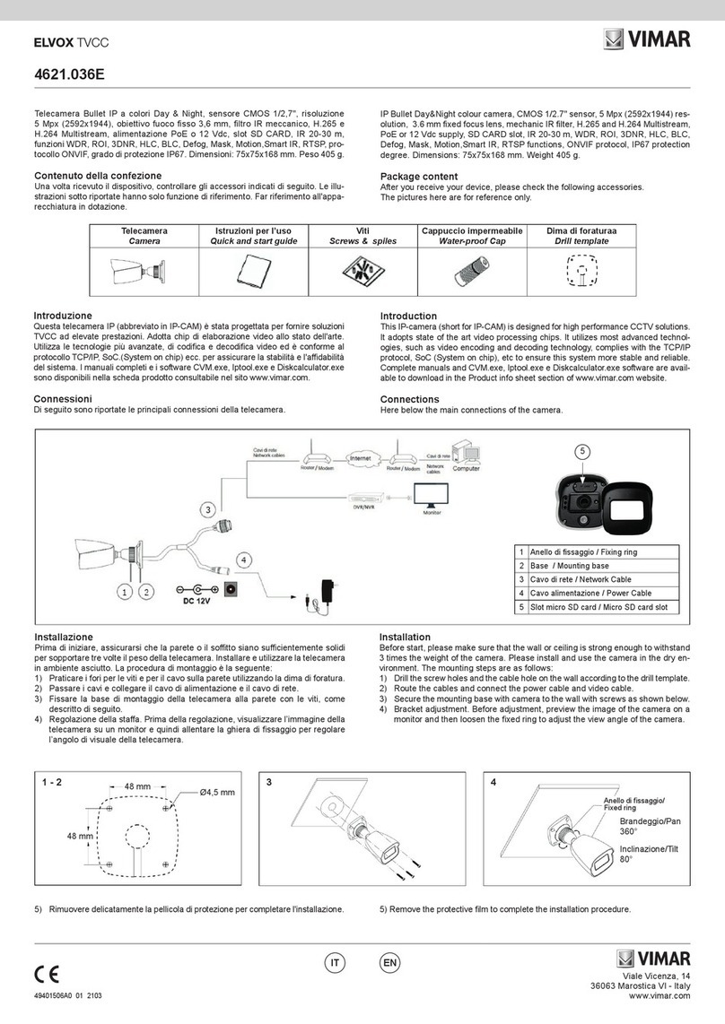
1) Praticare i fori per le viti e per il cavo sulla parete utilizzando la dima di foratura
(Fig. 3).
2) Passare i cavi e collegare il cavo di alimentazione e il cavo di rete.
3)
Posizionare la telecamera sulla parete o sul so󰀩tto in base al foro praticato (Fig. 4).
4) Fissare le due molle per bloccare la speed dome (Fig. 5).
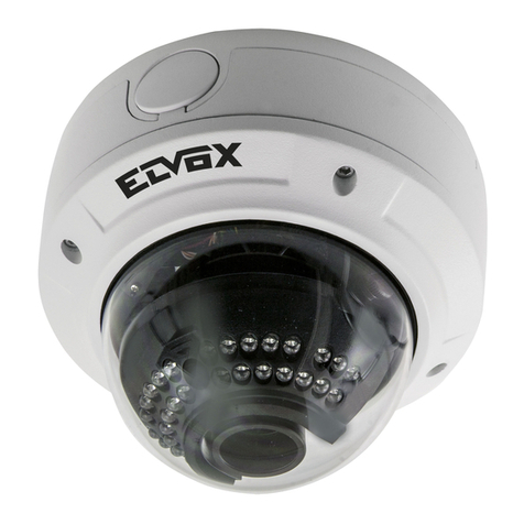
Telecamera Speed Dome IP 3 Mpx da incasso (2048 × 1536), sensore CMOS
1/2,8", obiettivo 5.5 ~ 110 mm, ltro IR meccanico, zoom ottico 20x, slot SD CARD,
funzioni WDR, BLC e 3D DNR, RTSP, protocollo ONVIF, uscita CVBS, gestione al-
larmi 4IN/1OUT, RS485, alimentazione 24 Vdc max 30 W, completa di alimentatore.
Dimensioni ø210x240 mm. Peso 2500 g.
Introduzione
Questa telecamera IP Speed Dome è stata progettata per fornire soluzioni TVCC
ad elevate prestazioni. La tecnologia di ip digitale consente di riprendere immagini
in tutte le direzioni e monitorare senza punti ciechi. Adotta chip di elaborazione
video allo stato dell'arte. Utilizza le tecnologie più avanzate di codica e decodica
video ed è conforme al protocollo TCP/IP, SoC (System on Chip) per assicurare la
stabilità e l'a󰀩dabilità del sistema.
I manuali completi e i software CVM.exe, Iptool.exe e Diskcalculator.exe sono di-
sponibili nella scheda prodotto consultabile nel sito www.vimar.com
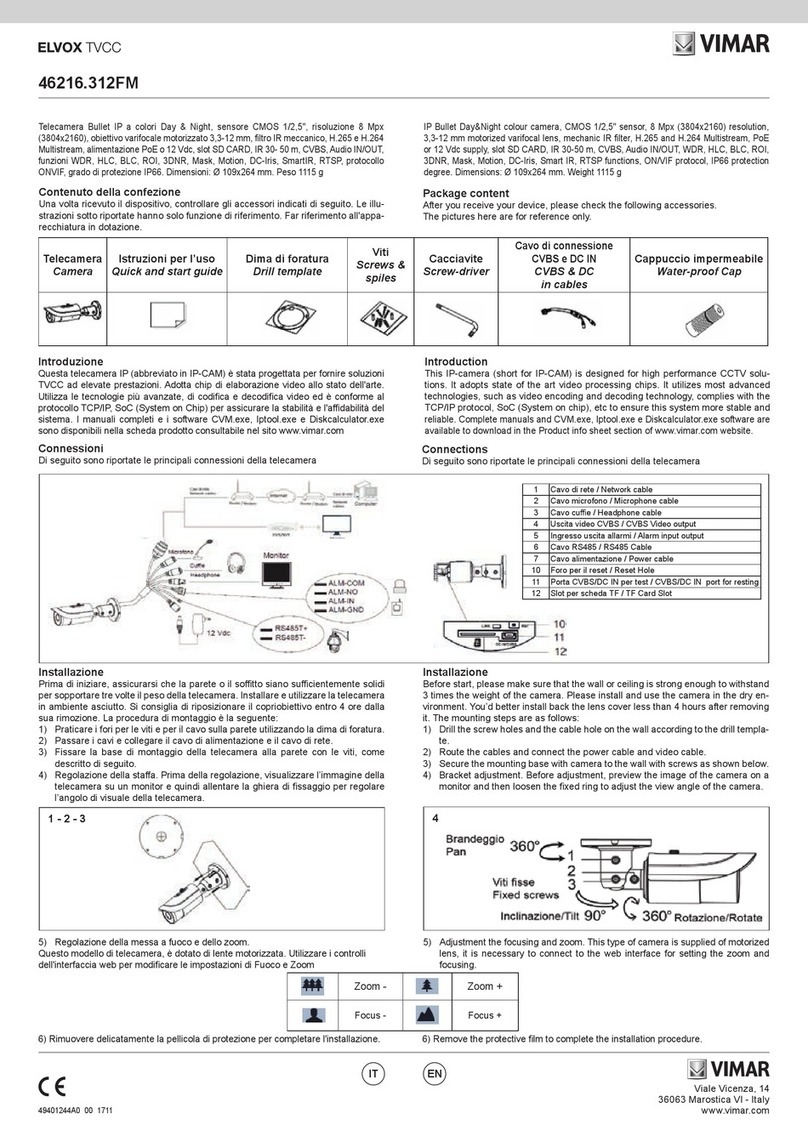
Connessioni
Di seguito sono riportate le principali connessioni della telecamera.
1 LAN
2 Uscita HP Audio
3 Ingresso MIC
4 Ingresso allarme/Uscita allarme
5 Alimentazione
6 RS485
7 Uscita CVBS Video
IP Speed Dome camera, for ush mounting, (2048 × 1536), CMOS 1/2,8" sensor,
5.5 ~ 110 mm lens, mechanical IR lter, 20x optic zoom, SD CARD slot, WDR, BLC
and 3D DNR, RTSP functions, ONVIF protocol, CVBS ouputs, 4IN/1OUT alarm
controls, RS485, supply voltage 24 Vdc max 30 W, power supply unit supplied.
Dimensions ø210x240 mm. Weight 2500 g.
Introduction
This Speed Dome IP-camera is designed for high performance CCTV solutions. Its
digital ip technology makes omni-directional and non-blind-spot monitoring into
reality. It adopts state of the art video processing chips. It utilizes most advanced
technologies, such as video encoding and decoding technology, complies with
theTCP/IP protocol, SoC (System on chip), etc to ensure this system more stable
and reliable.
Complete manuals and CVM.exe, Iptool.exe e Diskcalculator.exe software are
available to download in the Product info sheet section of www.vimar.com website.
Connections
Here below the main connections of the camera
1 LAN
2 HP Audio Out
3 MIC In
4 Alarm In/Alarm Out
5 Power
6 RS485
7 CVBS Video out
Install TF Card and Power Connection
Install Storage Card:
1 - Loosen the xed screws of the rear as shown below (Fig. 1).
2 - Insert the TF card into the storage card slot (Fig. 2).
3 - Install back the cover back.
Camera Installation
Before start, please make sure that the wall or ceiling is strong enough to withstand
3 times the weight of the camera. Please install and use the camera in the dry
environment. The mounting steps are as follows:
1) Drill the screw holes and the cable hole on the wall according to the drill templa-
te (Fig. 3).
2) Route the cables and connect the power cable and video cable.
3) Put the speed dome into the wall or ceiling according to the line cut (Fig. 4).
4) Fasten the two irons to x the speed dome (Fig. 5).
1
2
3
4
6
7
5
DC24V
Molla di ssaggio
Fixed iron
Inserire la scheda TF
Insert TF card
Fig. 3 Fig. 4 Fig. 5
Fig. 1 Fig. 2
Viale Vicenza, 14
36063 Marostica VI - Italy
www.vimar.com
46235.020CI
49401247A0 01 1701
ENIT
Descrizione/Description Colore / Color
Allarme-IN1/Alarm-IN1 Viola / Purple
Allarme-IN2/Alarm-IN2 Grigio / Grey
Allarme-IN3/Alarm-IN3 Bianco / White
Allarme-IN4/Alarm-IN4 Rosa / Pink
Allarme-n-COM/Alarm-n-COM Nero / Black
Allarme-OUT +/Alarm-OUT + Rosso/Red
Allarme-OUT -/Alarm-OUT - Marrone-Nero/Brown-Black
Descrizione / Description Colore / Color
RS485TA Giallo / Yellow
RS485TB Arancio / Orange
Contatti N.O./ Contacts N.O.
Connessione alla rete Ethernet
Come esempio, accediamo alla telecamera IP attraverso la LAN. In una LAN è
possibile accedere in due modi:
1. Accesso tramite IP-Tool;
2. Accesso diretto tramite Internet Explorer
Accesso alla telecamera tramite IP-Tool
1- Assicurarsi che la telecamera e il PC siano connessi alla LAN.
2-
Eseguire il download di IP-Tool dalla sezione prodotto del sito http://www.vimar.com
e installarlo sul computer. Inne, avviare IP-Tool come mostrato di seguito.
3- Modicare l'indirizzo IP. L'indirizzo IP predenito di questa telecamera è
192.168.226.201. Fare clic sulle informazioni della telecamera elencate nella
tabella sopra riportata per visualizzare le informazioni di rete sulla destra. Mo-
dicare l'indirizzo IP e il gateway della telecamera e assicurarsi che l'indirizzo
di rete si trovi nello stesso segmento della rete locale del computer. Modicare
l'indirizzo IP del dispositivo in base alla situazione specica.
Network Connections
Here we take accessing IP camera via LAN for example. In LAN, there
are two ways to access.
1. Access through IP-Tool;
2. Directly Access through IE Browser
Access the camera through IP-Tool
1- Make sure that the camera and the PC are well connected to the LAN.
2- Download IP-Tool from product section of http://www.vimar.com website and
then install it in the computer. After that, run the IP-Tool as shown below.
3 - Modify the IP address. The default IP address of this camera is 192.168.226.201.
Click the information of the camera listed in the above table to show the network
information on the right hand. Modify the IP address and gateway of the camera
and make sure its network address is in the same local network segment as
the computer’s. Please modify the IP address of your device according to the
practical situation.
La PTZ Art. 46235.020CI può gestire no a n°4 ingressi e 1 uscita allarme, con collega-
mento diretto degli allarmi sui contatti della PTZ, secondo lo schema di
Fig.
6
.
PTZ Art. 46235.020CI can handle up to No. 4 inputs and 1 alarm output, with direct
connection to the alarm contacts of PTZ, according to the diagram of Fig. 6.
-
+
5-12 Vdc
LA
N
MIC
HP
VIDEO
POWER
ALARM
Fig. 6
Viale Vicenza, 14
36063 Marostica VI - Italy
www.vimar.com
46235.020CI
49401247A0 01 1701
ENIT
Ad esempio, l'indirizzo IP del computer in uso è 192.168.1.4. Di conseguenza l'indirizzo
della telecamera deve essere cambiato in 192.168.1.X. Dopo la modica inserire la pas-
sword di amministratore e fare clic sul pulsante "Modica" per modicare l'impostazione.
4 - Fare doppio clic sull'indirizzo IP, il sistema aprirà Internet Explorer per collegare
la telecamera IP. Internet Explorer scarica automaticamente i controlli ActiveX.
Dopo il download si apre la nestra di accesso.
Inserire il nome utente e la password per accedere.
Il nome utente predenito è "admin" e la password "123456".
Accesso diretto da Internet Explorer
Le impostazioni di rete predenite sono indicate di seguito:
Indirizzo IP: 192.168.226.201
Subnet Mask: 255.255.255.0
Gateway: 192.168.226.1
HTTP: 80
Data port (Porta dati): 9008
For example, the IP address of your computer is 192.168.1.4. So the IP address of
the camera shall be changed to 192.168.1.X. After modication, please input the
password of the administrator and click “Modify” button to modify the setting.
4 - Double click the IP address and then the system will pop up the IE browser to
connect IP-CAM. IE browser will auto download the Active X control. After down-
loading, a login window will pop up.
The default password of the administrator is “123456”.
Input the username and password to log in.
The default username is “admin”; the default password is “123456”.
Directly Access through IE
The default network settings are as shown below:
IP address: 192.168.226.201
Subnet Mask: 255.255.255.0
Gateway: 192.168.226.1
HTTP: 80
Data port: 9008
La password predenita dell'amministratore è "123456".
46235.020CI
Telecamera
Cam
Sensore/ Sensor 1/2,8" CMOS Scansione progressiva 3 Mpx - 1/ 2.8" CMOS progressive scan 3 Mpx
Pixel immagine/Pixel image 2048 X 1536
Sensibilità/ Sensitivity 0.01 [email protected], AGC ON
Obiettivo/Lens Zoom ottico 20X (5.5 - 110 mm) - Optic zoom 20X (5.5 - 110 mm)
Angolo di visione / Vision corner 58° Wide - 3° Tele
Immagine
Image
Compressione Video/Video compression H.264 - H.265
Bit Rate 64Kbs ~ 8Mbs
Frame rate primario
Primary frame rate
Frame rate secondario
Secondary frame rate
30 Fps (2048 X 1536)
30 Fps (1920 X 1080)
30 Fps (1280 X 720)
30 Fps (1280 X 720)
30 Fps (D1)
30 Fps (CIF)
30 Fps (480 X 240)
Codica/ Codication VBR/CBR
Qualità/Quality Livello - Level VBR 5, CBR illimitato - unlimited
Connessioni
Connections
Network RJ45
Uscita Video CVBS/CVBS video output Sì - Yes
SD card Si non inclusa - Yes not included (128GB MAX)
RS485 Sì - Yes
Audio In / out 1/1
Allarme / Alarm In / out 4/1
Funzioni
Functions
Funzioni/Functions WDR, smart IR, 3D DNR, motion, BLC, Defog
Sorveglianza remota/remote control Browser IE, CMS per controllo da remoto - CMS for remote control
Utenti online/Online users 4 utenti, supporta la trasmissione su più ussi in tempo reale -
4 users, transmission supported on more ux in real time
Protocollo di rete/Network protocol TCP/IP, UDP, DHCP, NTP, RTSP, PPPoE, DDNS, SMTP, FTP
Compatibilità/Compatibility Onvif
Archiviazione/Storage Archiviazione su scheda TF, Archiviazione remota - TF-card storage, Remote storage
Giorno e Notte / Day&Night ICR
Limite/Limit Pan Tilt 360° continuo, 0° a 90° auto Flip
Preset 255
Cruise/Track 8/4
Altro
Other
PoE No
Range IR No
Grado/Degree IP/IK - / -
Range temperatura/Temperature range -10° C / + 40°C con umidità - with humidity 10% - 90%
Alimentazione/Power supply 24 Vdc
Consumi/Consumptions 30 W
Dimensioni/Dimensions (mm) Ø 210x240
Peso/Weight (g) 2500
Note RTSP, multi-stream alimentatore incluso - included power supply
Viale Vicenza, 14
36063 Marostica VI - Italy
www.vimar.com
46235.020CI
49401247A0 01 1701
ENIT
Descrizione Preset / Preset Description
Chiama Preset/
Call Preset
Call No. 90 Preset Run track 1
Call No. 91 Preset Run cruise 1
Call No. 92 Preset Run cruise 2
Call No. 93 Preset Run cruise 3
Call No. 94 Preset Run cruise 4
Call No. 95 Preset Menu OSD / OSD menu
Call No. 97 Preset Abilita scansione casuale / Enable random scan
Call No. 99 Preset Abilita P-SCAN / Enable P-PSCAN
Impostare Preset
Set Preset
Set No. 91 Preset Impostare scansione casuale; Task richiama in automatico il punto di inizio /
Set random scan; Task auto call the beginning point
Set No. 92 Preset Imposta limite sinistro di P-PSCAN / Set left border of P-PSCAN
Set No. 93 Preset Imposta limite destro di P-PSCAN / Set right border of P-PSCAN
Set No.94 Preset tre volte /
Set No.94 Preset three times
Impostare il valore limite dell'IR vicino e medio /
Set the boundary value of the near and middle infrared light
Set No.95 Preset tre volte /
Set No.95 Preset three times
Impostare il valore limite dell'IR medio e lontano /
Set the boundary value of the middle and far infrared light
Regole di installazione.
L’installazione deve essere effettuata da personale qualificato con l’osservanza
delle disposizioni regolanti l’installazione del materiale elettrico in vigore nel paese
dove i prodotti sono installati.
Installations rules.
Installation should be carried out by qualied sta󰀨 in compliance with the current
regulations regarding the installation of electrical equipment in the country where
the products are installed.
RAEE - Informazione agli utilizzatori
Il simbolo del cassonetto barrato riportato sull’apparecchiatura o sulla
sua confezione indica che il prodotto alla ne della propria vita utile deve
essere raccolto separatamente dagli altri riuti. L’utente dovrà, pertanto,
conferire l’apparecchiatura giunta a ne vita agli idonei centri comunali di
raccolta di󰀨erenziata dei riuti elettrotecnici ed elettronici. In alternativa
alla gestione autonoma, è possibile consegnare gratuitamente l’apparec-
chiatura che si desidera smaltire al distributore, al momento dell’acqui-
sto di una nuova apparecchiatura di tipo equivalente. Presso i distributori
di prodotti elettronici con supercie di vendita di almeno 400 m2 è inoltre
possibile consegnare gratuitamente, senza obbligo di acquisto, i prodotti
elettronici da smaltire con dimensioni inferiori a 25 cm. L’adeguata rac-
colta di󰀨erenziata per l’avvio successivo dell’apparecchiatura dismessa al
riciclaggio, al trattamento e allo smaltimento ambientalmente compatibile
contribuisce ad evitare possibili e󰀨etti negativi sull’ambiente e sulla salute
e favorisce il reimpiego e/o riciclo dei materiali di cui è composta l’appa-
recchiatura.
WEEE - Information for users
If the crossed-out bin symbol appears on the equipment or packaging, this
means the product must not be included with other general waste at the
end of its working life. The user must take the worn product to a sorted wa-
ste center, or return it to the retailer when purchasing a new one. Products
for disposal can be consigned free of charge (without any new purchase
obligation) to retailers with a sales area of at least 400 m2, if they measure
less than 25 cm. An e󰀩cient sorted waste collection for the environmental-
ly friendly disposal of the used device, or its subsequent recycling, helps
avoid the potential negative e󰀨ects on the environment and people’s health,
and encourages the re-use and/or recycling of the construction materials.
Conformità Normativa
Direttiva BT, Direttiva EMC
EN 60950-1, EN 55032, EN 55024, EN 61000-3-2, EN 61000-3-3
Conformity to Standards
Directiv BT, Directiv EMC
EN 60950-1, EN 55032, EN 55024, EN 61000-3-2, EN 61000-3-3
Congurazione del router / Router Setup
Other Vimar Security Camera manuals

Vimar 46222.036.01 User manual

Vimar

Vimar 46222.036.01 User manual

Vimar ELVOX 4652.2812F User manual

Vimar

Vimar ELVOX 4652.2812F User manual

Vimar 5vl5 User manual

Vimar

Vimar 5vl5 User manual

Vimar ELVOX 4622.028B User manual

Vimar

Vimar ELVOX 4622.028B User manual

Vimar ELVOX 46216.312C.01 User manual

Vimar

Vimar ELVOX 46216.312C.01 User manual

Vimar ELVOX TVCC 4622.028EA User manual

Vimar

Vimar ELVOX TVCC 4622.028EA User manual

Vimar ELVOX 4624.028EAE User manual

Vimar

Vimar ELVOX 4624.028EAE User manual

Vimar Elvox 4622.2812EMS User manual

Vimar

Vimar Elvox 4622.2812EMS User manual

Vimar ELVOX TVCC 4624.036E User manual

Vimar

Vimar ELVOX TVCC 4624.036E User manual

Vimar ELVOX TVCC 4625.028B User manual

Vimar

Vimar ELVOX TVCC 4625.028B User manual

Vimar Elvox 4622.2812EAE User manual

Vimar

Vimar Elvox 4622.2812EAE User manual

Vimar ELVOX 4652.028B User manual

Vimar

Vimar ELVOX 4652.028B User manual

Vimar ELVOX 46916.004 User manual

Vimar

Vimar ELVOX 46916.004 User manual

Vimar ELVOX 46226.312C.01 User manual

Vimar

Vimar ELVOX 46226.312C.01 User manual

Vimar ELVOX 46516.213D User manual

Vimar

Vimar ELVOX 46516.213D User manual

Vimar ELVOX TVCC 46226.312FM User manual

Vimar

Vimar ELVOX TVCC 46226.312FM User manual

Vimar 46242.036C User manual

Vimar

Vimar 46242.036C User manual

Vimar ELVOX TVCC 46212.036B.01 User manual

Vimar

Vimar ELVOX TVCC 46212.036B.01 User manual

Vimar ELVOX TVCC 4652.2713EM User manual

Vimar

Vimar ELVOX TVCC 4652.2713EM User manual

Vimar ELVOX 46241.036A User manual

Vimar

Vimar ELVOX 46241.036A User manual

Vimar ELVOX TVCC 4651.2713BLM User manual

Vimar

Vimar ELVOX TVCC 4651.2713BLM User manual

Vimar ELVOX 46635.036 User manual

Vimar

Vimar ELVOX 46635.036 User manual

Vimar ELVOX TVCC 4622.2812FKA User manual

Vimar

Vimar ELVOX TVCC 4622.2812FKA User manual

Vimar ELVOX 46316.210A User manual

Vimar

Vimar ELVOX 46316.210A User manual

Popular Security Camera manuals by other brands

Wisenet PND-9080R quick guide

Wisenet

Wisenet PND-9080R quick guide

Samsung SCC-C9302(F) user manual

Samsung

Samsung SCC-C9302(F) user manual

TRASSIR TR-D2221WDIR4W manual

TRASSIR

TRASSIR TR-D2221WDIR4W manual

Samsung SCD-3080 Series user guide

Samsung

Samsung SCD-3080 Series user guide

ENJI PRIME Dice Camera user guide

ENJI PRIME

ENJI PRIME Dice Camera user guide

Sanyo VCC-HD2100 - Full HD 1080p Network Camera Specifications

Sanyo

Sanyo VCC-HD2100 - Full HD 1080p Network Camera Specifications

Intellisystem ThermalTronix TT-1100PXB-DVACS user manual

Intellisystem

Intellisystem ThermalTronix TT-1100PXB-DVACS user manual

JAGER PRO I.C.E Operation manual

JAGER PRO

JAGER PRO I.C.E Operation manual

Bosch WZ16 installation manual

Bosch

Bosch WZ16 installation manual

Axis 225FD installation guide

Axis

Axis 225FD installation guide

Clover HDC518 install guide

Clover

Clover HDC518 install guide

D-Link DCS-2670L Quick installation guide

D-Link

D-Link DCS-2670L Quick installation guide

Lorex VQ1536HR Specifications

Lorex

Lorex VQ1536HR Specifications

Vitek VT-PIRC2H Specifications

Vitek

Vitek VT-PIRC2H Specifications

Monacor AV-432SET instruction manual

Monacor

Monacor AV-432SET instruction manual

Vivotek FD8135H user manual

Vivotek

Vivotek FD8135H user manual

Iconix HD-RH1 user manual

Iconix

Iconix HD-RH1 user manual

LevelOne CamCon FCS-1070 Specifications

LevelOne

LevelOne CamCon FCS-1070 Specifications

manuals.online logo
manuals.online logoBrands
  • About & Mission
  • Contact us
  • Privacy Policy
  • Terms and Conditions

Copyright 2025 Manuals.Online. All Rights Reserved.